Air Lift LoadLifter 5000 Series Installation Manual
Hide thumbs
Also See for LoadLifter 5000 Series:
- Installation manual (20 pages) ,
- Installation manuals (16 pages) ,
- Installation manual (20 pages)
Table of Contents
Advertisement
S E R I E S
GM Silverado/Sierra 1500
Kits 57288 | 88288 | 89288
GM Trail Boss/Sierra AT4
Kits 57388 | 88388 | 89388
MN-1085 • (011810) • ERN 9073
For maximum effectiveness and safety, please read these instructions
completely before proceeding with installation.
Failure to read these instructions can result in an incorrect installation.
Installation
Guide
Advertisement
Table of Contents

Subscribe to Our Youtube Channel
Related Manuals for Air Lift LoadLifter 5000 Series


Summary of Contents for Air Lift LoadLifter 5000 Series
- Page 1 Installation Guide S E R I E S GM Silverado/Sierra 1500 Kits 57288 | 88288 | 89288 GM Trail Boss/Sierra AT4 Kits 57388 | 88388 | 89388 For maximum effectiveness and safety, please read these instructions completely before proceeding with installation. Failure to read these instructions can result in an incorrect installation.
- Page 2 IDENTIFYING THE DIFFERENCES BETWEEN KITS Should you need to contact Air Lift customer service, you will need to know which kit you are inquiring about: standard LoadLifter 5000, LoadLifter 5000 Ultimate or LoadLifter 5000 Ultimate Plus. The kits are easily identifiable by looking at the roll plates and air lines.
-
Page 3: Table Of Contents
TABLE OF CONTENTS A. Installation Diagram ....... . 2 B. Hardware and Tools Lists ......3 C. -
Page 4: Installation Diagram
LoadLifter 5000 Series A. Installation Diagram NOTE: If the truck has fifth-wheel hitch brackets along the side of the frame, these U-bolts may not be used. * Optional hardware for vehicles equipped with fifth-wheel hitches that have frame side plates (see page 9 for details) fig. -
Page 5: Hardware And Tools Lists
18501 M8 Flat washer............2 21709 Schrader valve with cap & nut ........ 2 21813 AN to PTC fitting ............. 2 Missing or damaged parts? Call Air Lift customer Missing or damaged parts? Call Air Lift customer STOP! service at (800) 248-0892 for a replacement part. -
Page 6: Introduction
LoadLifter 5000 Series C. Introduction C. Introduction C. Introduction The purpose of this publication is to assist with the installation and maintenance of the LoadLifter 5000 series air spring kits. All LoadLifter 5000 series kits utilize sturdy, reinforced, commercial-grade single or double, depending on the kit, convolute bellows. The air springs are manufactured like a tire with layers of rubber and cords that control growth. -
Page 7: Installing The Loadlifter 5000 Series System
LoadLifter 5000 Series D. Installing the LoadLifter 5000 Series System GETTING STARTED 1. Raise and support the vehicle in a way, using safety stands or equivalent, that the axle can be safely dropped away from the frame. This will need to be done for the air spring assembly to be put into position between the axles and frame (Fig. - Page 8 LoadLifter 5000 Series 4. Using a T40 sized Torx bit, remove the two outer most Torx head screws on both wire harness guards, located on the front side of the axle (Fig D.6). Passenger's (Right) Side fig. D.6 5. Remove the brake line bracket attached to the axle under the leaf spring on both sides of the vehicle.
-
Page 9: Assembling The Air Springs
LoadLifter 5000 Series ASSEMBLING THE AIR SPRINGS 1. Place a 3/8"-16 x 3"carriage bolt (O) through the inner most square hole on the rear side of each lower bracket (B) (Fig. D.11). RIGHT LEFT fig. D.11 NOTE The radiused (rounded) edge of the roll plate (F) will be toward the air spring so that the air spring is seated inside the roll plate. -
Page 10: Installing The Air Springs
LoadLifter 5000 Series INSTALLING THE AIR SPRINGS 1. Drop the axle or raise the frame to make room to put the assemblies into position. ENSURE VEHICLE IS PROPERLY SUPPORTED PRIOR TO BEGINNING INSTALLATION. CAUTION 2. Place the assemblies on the lower strike plate with the fitting side of the assembly to the outside (wheel side) of the vehicle. - Page 11 LoadLifter 5000 Series 2. Lower the vehicle or raise the axle while inserting the threaded portions of the U-bolts (I) through the corresponding holes in the upper brackets (A). Install flange nuts (N) finger tight (Fig. D.19). fig. D.19 3. Adjust the upper bracket (A) as needed to veritcally align the air spring with the frame (or as close to perpendicular as possible).
-
Page 12: Installing The Air Lines
or bumper Hex nuts Schrader LoadLifter 5000 Series valve Air line hex nut E. Installing the Air Lines Star washer Rubber washer 5/16” (8mm) hole Air lines are routed USE IN A. Inside fuel from the air springs tank filler Flat washer to Schrader valves. -
Page 13: Installing Braided Stainless Steel Air Lines
LoadLifter 5000 Series INSTALLING BRAIDED STAINLESS STEEL AIR LINES KEEP THE AIR LINE AWAY FROM THE FUEL LINE, BRAKE LINES AND ELECTRICAL CAUTION WIRES. 1. Use zip ties to secure Air Line Setup Without Compressor System the air line to fixed points Vehicle body Flat Braided stainless steel... -
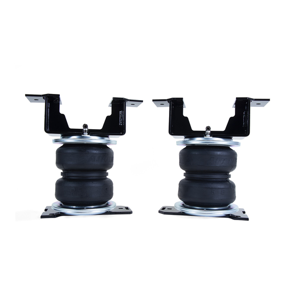
Page 14: Finished Installation
LoadLifter 5000 Series F. Finished Installation 1. The images show the finished installation of both sides (Figs. F.1, F.2, F.3 & F.4). NOTE Finished installation images show the LoadLifter 5000 Ultimate Plus kit installed. Passenger's Driver's (left) (right) side side view. view. -
Page 15: Installation Checklist
GROSS VEHICLE WEIGHT RATING. Limited Warranty and Return Policy Air Lift Company provides a limited lifetime warranty to the original purchaser of its load support products, that the products will be free from defects in workmanship and materials when used... - Page 16 For calls outside the U.S. or Canada, dial (517) 322-2144. Air Lift Company • 2727 Snow Road • Lansing, MI 48917 or P.O. Box 80167 • Lansing, MI 48908-0167 Air Lift Company reserves the right to make changes and improvements to its products and publications at any time.
Need help?
Do you have a question about the LoadLifter 5000 Series and is the answer not in the manual?
Questions and answers