Allen-Bradley PLC-5 User Manual
Ethernet
interface module
Hide thumbs
Also See for PLC-5:
- User manual (388 pages) ,
- Design manual (195 pages) ,
- Quick start manual (29 pages)
Table of Contents
Advertisement
Advertisement
Chapters
Table of Contents

Related Manuals for Allen-Bradley PLC-5


Summary of Contents for Allen-Bradley PLC-5
- Page 1 Allen-Bradley User PLC-5 Ethernet Interface Module Manual (Cat. No. 1785-ENET)
- Page 2 Attention statements help you to: identify a hazard avoid the hazard recognize the consequences Important: Identifies information that is critical for successful application and understanding of the product. ControlNet is a trademark; PLC is a registered trademark of Allen-Bradley Company, Inc.
-
Page 3: Table Of Contents
Table of Contents Chapter 1 Quick Start Installing and Configuring the Interface Module ....1–2 What You Have Done ........1–7 What’s Next . - Page 4 Table of Contents Chapter 4 Communicating Via the Interface Module Using This Chapter ........4–1 Applying Power to the Chassis .
- Page 5 Use this manual if you are responsible for designing, installing, Manual programming, or troubleshooting control systems that use Allen-Bradley programmable controllers or interface modules. You should have a basic understanding of PLC-5 programmable controller products and the following Ethernet-related topics: TCP/IP protocol Internet addressing...
- Page 6 Describes the status LED error codes. Related Documentation For additional information regarding Allen-Bradley programmable controllers and related products, see the Enhanced and Ethernet PLC-5 Programmable Controllers User Manual, publication 1785-6.5.12. To obtain a copy, contact your local Allen-Bradley office or distributor. Publication 1785-6.5.19–June 1996...
- Page 7 Allen-Bradley offers support services worldwide, with over 75 Sales/Support Offices, 512 authorized Distributors and 260 authorized Systems Integrators located throughout the United States alone, plus Allen-Bradley representatives in every major country in the world. Local Product Support Contact your local Allen-Bradley representative for:...
-
Page 8: Quick Start
Chapter Quick Start This chapter can help you get started quickly using the PLC-5 Ethernet Interface Module. We base the procedures here on the assumption that you have an understanding of: PLC-5 products Status TCP/IP protocol indicator Internet addressing Transmit... -
Page 9: Installing And Configuring The Interface Module
Check the contents of your shipment. Quantity Description PLC-5 Ethernet Interface Module (1785-ENET) Connector it containing 1 PLC-5 58-pin connector header Connector kit containing 1 PLC-5 58-pin connector header Industrial Automation Wiring and Grounding Guidelines, publication 1770-4.1 PLC-5 Ethernet Interface Module User Manual, publication 1785-6.5.19... - Page 10 You do not need to key the connector. Reference Use the captive screws to connect the interface module to the processor. Chapter 2 Installing the Interface Module Front of the interface module Front of the PLC-5 processor Installed connector header 20597–M Publication 1795-6.5.19–June 1996...
- Page 11 1–4 Quick Start Reference Install the interface module/processor combination in the left-most slot Chapter 2 of the 1771 I/O chassis. Installing the Interface Module Be sure power to the 1771 I/O chassis is OFF. 20582–M Reference Chapter 3 Configuring the Assign an IP address to the interface module.
- Page 12 Be sure channel 3A is designated as the channel supporting the 1785-ENET module. If you are using 6200 Programming Software, you must have revision 5.2 or later to configure Channel 3A for Ethernet communication. The PLC-5 processor must also contain the proper firmware revision. See page 2-1 for information about firmware revision levels.
- Page 13 1–6 Quick Start Reference Chapter 4 Apply power to the I/O chassis and processor. Communicating Via the Interface Module Turn on the I/O chassis power supply. 20634–M Reference Chapter 4 Establish an Ethernet connection. Communicating Via the Interface Module Reference Chapter 4 Check that the module is operating correctly.
-
Page 14: What You Have Done
Ethernet link. If your module is operating successfully, it is not necessary to continue reading this manual. For information about operating PLC-5 processors within your control system, refer to the Enhanced and Ethernet PLC-5 Programmable Controllers User Manual, publication 1785-6.5.12. What’s Next If necessary, refer to the remainder of this manual for more detailed information about installing and configuring the interface module. -
Page 15: Installing The Interface Module
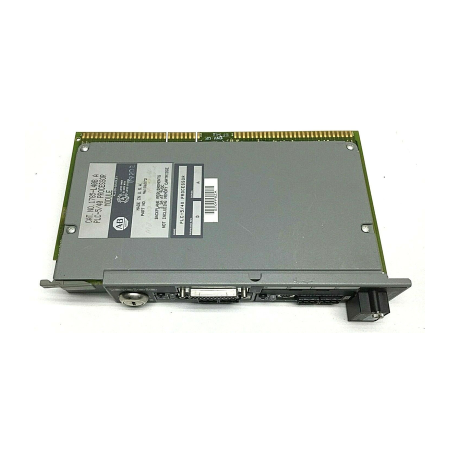
2–8 indicator The PLC-5 Ethernet Interface Module is a single-slot module that attaches to the side of any enhanced PLC-5 Series B or later processor to provide Ethernet connectivity for the attached processor. When used with The interface module provides... -
Page 16: Before You Begin
Allen-Bradley assigns each PLC-5 Ethernet interface module an Ethernet hardware address at the factory. Look for this address either: in the back, upper corner of your module in the channel 3A configuration screen of your PLC-5 programming software Ethernet hardware... -
Page 17: Necessary Equipment
Installing the Interface Module 2–3 Necessary Equipment Locate and have ready all the tools and equipment necessary for installation: I/O Chassis PLC-5 Processor (1771-A1B/B, -A2B/B, -A3/B or -A4B/B) Supported processors and current firmware (see page 2-1) phillips Grounding screwdriver Wrist Strap... -
Page 18: Complying With European Union Directives
Programmable Controllers, Part 2 – Equipment Requirements and Tests. For specific information that this EN requires, see the appropriate sections in this publication, as well as the following Allen-Bradley publications: Industrial Automation Wiring and Grounding Guidelines (for noise immunity), publication 1770-4.1 Guidelines for Handling Lithium Batteries, publication AG-5.4... -
Page 19: Installing The Interface Module
Installing the Interface Module 2–5 Installing the To install the PLC-5 Ethernet Interface Module, you must: Interface Module attach the connector header to the processor attach adhesive washers to the processor connect the interface module to the processor install the combination into the chassis... -
Page 20: Connect The Interface Module To The Processor
Front of the interface module interface module to those on the connector header. Press the interface module into the connector header. Tighten the screws. Front of the PLC-5 processor Installed connector header 20597–M Important: Make sure you carefully align the pins and holes before you press the interface module into the connector header. -
Page 21: Install The Processor/Interface Module Into The Chassis
Installing the Interface Module 2–7 Install the Processor/Interface Module into the Chassis To install the attached modules into the 1771 I/O chassis, follow these steps: Verify that power to the 1771 I/O chassis is OFF. Raise the locking bar. Remember to wear a grounding wrist strap to guard against ESD. -
Page 22: Removing The Interface Module
Lift the ejector tabs on the front of each module simultaneously and remove the connected modules. Loosen the four screws on the side of the interface module. Ethernet Interface Module PLC-5 20599–M processor Separate the interface module from the processor by placing your finger tips between the two modules. -
Page 23: Configuring The
Ethernet hardware address (see page 2–2) assign an IP address to the module Because the PLC-5 Ethernet Interface Module uses the TCP/IP protocol, each Ethernet hardware address on the network requires a unique IP address. -
Page 24: Configuring Channel 3A
1995. Use unique addresses that follow the basic TCP/IP guidelines. Configuring Channel 3A Once you know the unique IP address that you will assign to the PLC-5 Ethernet Interface Module, you must configure channel 3A so your network recognizes the module. To configure channel 3A, use your programming software... -
Page 25: Manually Entering Module Configuration Information
Broadcast Address the processor should respond The processor’s subnet mask See the Enhanced and Ethernet PLC-5 Programmable Controllers User Manual, Subnet Mask (used when network has subnets) publication 1785-6.5.12 for information about how to configure these advanced publication 1785-6.5.12 for information about how to configure these advanced Ethernet functions. -
Page 26: Dynamically Supplying Configuration Information Using Bootp
3–4 Configuring the Interface Module for Ethernet Communication3 Dynamically Supplying Configuration Information using BOOTP BOOTP is a protocol that will supply the interface module with configuration information at power-up. BOOTP lets you dynamically assign IP addresses to devices on the Ethernet link. To use BOOTP, a BOOTP server must exist on the local Ethernet subnet. -
Page 27: Using The Bootp Servers On The Utility Disk
The disk you received with your interface module contains Servers on the DOS-based and Windows-based BOOTP servers. Both provide Utility Disk BOOTP services for PLC-5 Ethernet Interface Modules and PLC-5 Ethernet processors. Regardless of the platform you are using, you must: install the boot-server utility disk... -
Page 28: Edit The Dos/Windows Bootp Configuration File
Important: Use this line as the configuration template for Ethernet devices. 2. Make one copy of the Ethernet device template for every PLC-5 Ethernet Interface Module in your system (i.e. one line per module). 3. Edit each copy of the template as follows: a. - Page 29 Configuring the Interface Module for Ethernet Communication3 3–7 Example In this example there are three PLC-5 processors (two enhanced processors and one Ethernet processor) with attached 1785-ENET interface modules and an HP 9000 workstation. The names and hardware addresses are device specific: Device...
-
Page 30: Run The Boot Server Utility
3–8 Configuring the Interface Module for Ethernet Communication3 Run the Boot Server Utility You can run either the DOS-based utility or the Windows-based BOOTP utility, but not both. then invoke this If you’re using executable from the page DOS command line 3–8 DTLBOOTD.EXE (specify optional... -
Page 31: Running The Windows-Based Utility
Configuring the Interface Module for Ethernet Communication3 3–9 2. Apply power to all chassis containing Ethernet PLC-5 processors and interface modules. At power-up, each PLC-5 Ethernet Interface Module broadcasts a BOOTP request if BOOTP was enabled at the Channel 3A Configuration screen. -
Page 32: Applying Power To The Chassis
Chapter Communicating Via the Interface Module4 Using This Chapter Once the PLC-5 Ethernet Interface Module is connected and configured, the interface module and the processor function as a unit. For information about See page Applying power to the chassis 4–1 Monitoring the LEDs 4–1... - Page 33 4–2 Communicating Via the Interface Module4 Table 4.A Indicator Lights on PLC-5 Ethernet Interface Module Indicator Color Description Probable Cause Recommended Action STAT Solid red Critical hardware Interface module Contact your local fault requires internal repair Allen-Bradley distributor Blinking red...
- Page 34 The table below lists all major processor fault codes pertinent to a sidecar module, such as the Ethernet interface module. For a complete list of fault codes for PLC-5 processors, see the Enhanced and Ethernet PLC-5 Programmable Controllers User Manual, publication 1785-6.5.12.
-
Page 35: Establishing An Ethernet Connection
To establish online communications, configure the online Ethernet Connection characteristics using your programming software package. Monitoring Ethernet Monitor the status of communication through the PLC-5 Ethernet Status Data interface module by accessing the Ethernet Channel 3A status screen. The diagnostic counter data displayed is stored in the diagnostics... - Page 36 Communicating Via the Interface Module4 4–5 Status field: Bytes: Displays the number of: 28-31 Octets received on the channel In Octets Ethernet 32-35 Octets sent on the channel Out Octets 36-39 Packets received on the channel, including broadcast packets In Packets 40-43 Packets sent on the channel, including broadcast packets Out Packets...
-
Page 37: Using The Message Instruction
4–6 Communicating Via the Interface Module4 Using the Message The message (MSG) instruction transfers up to 1000 elements of Instruction data; the size of each element depends on the data table section that you specify and the type of message command that you use. One binary element contains one 16-bit word, for example, and one floating-point element contains two 16-bit words. - Page 38 Whether the MSG instruction performs a read or write operation. The software toggles between: PLC-5 Typed Read, PLC-5 Typed Write, PLC-5 Typed Write to SLC, PLC-5 Typed Read from SLC, SLC Typed Logical Read, SLC Typed Logical Write, PLC-2 Unprotected Read, PLC-2 Unprotected Write, PLC-3 Word Range Read,...
-
Page 39: Interpreting Error Codes
4–8 Communicating Via the Interface Module4 Interpreting Error Codes When the processor/interface module detects an error during the transfer of message data, the processor sets the .ER bit and enters an error code that you can monitor from your programming software. Code (Hexadecimal—Word 1 of the Control Block) Description (Displayed on the Data Monitor Screen) 0037... -
Page 40: Identifying The Interface Module Within A Network
Communicating Via the Interface Module4 4–9 Known Restrictions in this When the PLC-5 processor faults, the interface module blinks the Release of the Interface error code 2 signifying a “bus error”. The proper error code for this Module error is 73, signifying that the PLC processor failed. This anomaly will be corrected in a later release of the interface module. - Page 41 Appendix Module Specifications PLC-5 Ethernet Interface Module (1785-ENET) Backplane Current 2.2A Heat Dissipation 37.54 BTU/hr Operating Temperature ..0 to 60 C (32-140 F) Environmental Conditions Storage Temperature ..-40 to 85 C (-40 to 185 F) Relative Humidity .
- Page 42 Appendix Performance Data PLC-5 Ethernet Interface Module (1785-ENET) The following tables show measured performance data for the 1785-ENET module. PEER-TO-PEER (Unsolicited) Operation: Words: MSG per second: ms per MSG: Words per second: READ 20.2 49.5 READ 19.8 50.5 READ 18.8 53.2...
- Page 43 Appendix SNMP Management Information Base (MIB) II Data Groups Simple Network Management Protocol (SNMP) specifies the diagnostic data that a host computer must maintain for a network management software to access. Hosts typically keep statistics on the status of their network interfaces, incoming and outgoing traffic, dropped datagrams, and error messages generated.
- Page 44 C–2 Variable Content TTL:Chap udplndataGrams datagrams delivered above udpNoPorts datagrams destined for unknown ports udplnErrors datagrams discarded due to format errors udpOutDatagrams datagrams sent from above udpLocalAddress local IP address udpLocalPort local UDP port ipForwarding acting as a gateway or host ipDefaultTTL default TTL for IP packets ipInReceives...
- Page 45 Variable Content TTL:Chap C–3 tcpRtoAlgorithm identifies retransmission algorithm tcpRtoMin minimum retransmission timeout in milliseconds tcpRtoMax maximum retransmission timeout in milliseconds tcpmaxConn maximum of simultaneous TCP connections allowed tcpActiveOpens number of active opens tcpPassiveOpens number of passive opens tcpAttemptFails number of failed connection attempts tcpEstabResets number of connections reset tcpCurrEstab...
- Page 46 Static RAM self-test failed Jump table wrong SONIC chip test failed FLASH BOOT area checksum incorrect PLC-5 dualport initialization failure PLC-5 not compatible with 1785-ENET Could not read FLASH id Could not erase FLASH bank Could not program FLASH bank Software initialization failure ENET firmware hardware fault 1785-6.5.19–June 1996...
- Page 47 D–2 Variable Content TTL:Chap Code Description ENET software failure Network system failure Lump system call failed Lump internal inconsistency PCCC system call failed PCCC internal inconsistency Dual port system call failed Dual port internal inconsistency ISR system call failed ISR internal inconsistency AC power fail Reset asserted Fault asserted...
- Page 48 A–1 boot-services DOS, 3–9 communication port, 4–4 Windows, 3–9 compatibility with processor firmware, 2–1 BOOTP connect, 1785-ENET to PLC-5, 2–6 defined, 3–5 disable, 3–3, 3–4 connecting to processor, aligning pins, 2–6 edit configuration file, 3–7 connector header enable, 3–5 aligning pins, 2–5...
- Page 49 Index I–2 edit BOOTPTAB.TXT file, 3–7 I/O addressing, A–1 electrostatic discharge damage, preventing, install 2–3 adhesive washers, 2–6 BOOTP utility, 3–6 environment, specifications, A–1 module, 2–5 equipment necessary, 2–3 screws, 2–6 quick start, 1–2 install in 1771 I/O chassis, 2–7 error codes, messaging, 4–9 installation of module, 2–1, 2–5 ESD, preventing, 2–3...
- Page 50 Index I–3 online communications, establishing, 4–4 quick start, 1–1 power, applying, quick start, 1–6 remove module, 2–8 power supply, 2–3, 2–5 required tools and equipment, 2–3 programs restoring programs, 4–10 restoring, 4–10 routing configurations, 4–4 saving, 4–10 publications, related, P–2 1785-6.5.19–June1996...
- Page 51 Philippines Poland Portugal Puerto Rico Qatar Romania Russia–CIS Saudi Arabia Singapore Slovakia Slovenia South Africa, Republic Spain Sweden Switzerland Taiwan Thailand Turkey United Arab Emirates United Kingdom United States Uruguay Venezuela Yugoslavia Allen-Bradley Headquarters, 1201 South Second Street, Milwaukee, WI 53204 USA, Tel: (1) 414 382-2000 Fax: (1) 414 382-4444 Publication 1785-6.5.19 – June 1996 955122-46 1785-6.5.19–June1996...
Need help?
Do you have a question about the PLC-5 and is the answer not in the manual?
Questions and answers