Table of Contents
Advertisement
QQ
3 7 63 1515 0
SERVICE MANUAL
Ver. 1.1 2007. 08
TE
L 13942296513
www
.
Sony Corporation
9-887-094-02
2007H04-1
eVehicle Division
© 2007. 08
Published by Sony Techno Create Corporation
http://www.xiaoyu163.com
Circuit system
Inputs
Input level adjustment range
Outputs
Speaker impedance
Maximum outputs
Rated outputs (supply voltage at 14.4 V)
Frequency response
Harmonic distortion
Low-pass filter
Power requirements
Power supply voltage
Current drain
Dimensions
Mass
Supplied accessories
Design and specifications are subject to change without
notice.
x
ao
u163
y
i
http://www.xiaoyu163.com
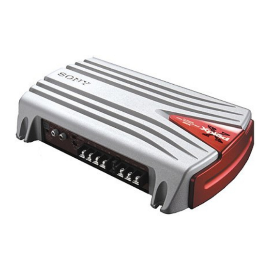
XM-552ZR
2 9
8
SPECIFICATIONS
OTL (output transformerless) circuit
Pulse power supply
RCA pin jacks
High level input connector
0.3 – 6 V (RCA pin jacks),
Q Q
2.8 – 12 V (High level input)
3
6 7
1 3
1 5
Speaker terminals
2 – 8 Ω (stereo)
4 – 8 Ω (when used as a bridging amplifier)
110 W × 2 (at 4 Ω)
350 W (BTL, at 4 Ω)
55 W × 2 (20 Hz – 20 kHz, 0.04% THD, at 4 Ω)
65 W × 2 (20 Hz – 20 kHz, 0.1% THD, at 2 Ω)
130 W (BTL) (20 Hz – 20 kHz, 0.1% THD,
at 4 Ω)
+0
5 Hz – 50 kHz (
dB)
–3
0.005% or less (at 1 kHz, 4 Ω)
80 Hz, –18 dB/oct
12 V DC car battery
(negative ground)
10.5 – 16 V
at rated output : 15 A (4 Ω, 55 W × 2)
Remote input : 1 mA
Approx. 306 × 55 × 201 mm (w/h/d)
not incl. projecting parts and controls
Approx. 2.0 kg not incl. accessories
Mounting screws (4)
High level input cord (1)
Protection cap (1)
STEREO POWER AMPLIFIER
co
.
9 4
2 8
E Model
0 5
8
2 9
9 4
2 8
m
9 9
9 9
1
Advertisement
Table of Contents

Related Manuals for Sony XM-552ZR


Summary of Contents for Sony XM-552ZR
-
Page 1: Service Manual
Mounting screws (4) High level input cord (1) Protection cap (1) Design and specifications are subject to change without notice. STEREO POWER AMPLIFIER u163 Sony Corporation 9-887-094-02 2007H04-1 eVehicle Division © 2007. 08 Published by Sony Techno Create Corporation http://www.xiaoyu163.com... -
Page 2: Table Of Contents
WITH MARK 0 ON THE SCHEMATIC DIAGRAMS AND IN damaged by heat. THE PARTS LIST ARE CRITICAL TO SAFE OPERATION. REPLACE THESE COMPONENTS WITH SONY PARTS WHOSE PART NUMBERS APPEAR AS SHOWN IN THIS MANUAL OR IN SUPPLEMENTS PUBLISHED BY SONY. -
Page 3: General
En este d’utilisation comme amplificateur en pont). • No conecte altavoces activos (con Dans ce cas, consultez votre distributeur Sony le caso, póngase en contacto con el distribuidor • Ne raccordez pas de haut-parleurs actifs (avec amplificadores incorporados) a los terminales plus proche. -
Page 4: Connections
XM-552ZR 3 7 63 1515 0 Connections Cautions Installation • Before making any connections, disconnect the together can generate some interference noise. Before Installation First, place the unit where you plan to install it, ground terminal of the car battery to avoid •... - Page 5 XM-552ZR 3 7 63 1515 0 Notes on the power supply Input Connections/Connexions d’entrée/Conexiones de entrada • Connect the +12 V power supply wire only after all • All power wires connected to the positive battery the other wires have been connected.
- Page 6 XM-552ZR 3 7 63 1515 0 Table of crossover values for 6 dB/octave Notes 1-Speaker System (with Input Connection B or D) • When using passive crossover networks in a multi- (4 Ω) (Speaker Connections 4) Système à 1 haut-parleur (avec connexion d’entrée B ou D)
-
Page 7: Disassembly
XM-552ZR SECTION 2 DISASSEMBLY 3 7 63 1515 0 Note : This set can be disassemble according to the following sequence. 2-1. BOTTOM PLATE (Page 7) 2-2. AMP BOARD SECTION (Page 8) 2-3. PANEL (FRONT) (Page 8) Note : Follow the disassembly procedure in the numerical order given. - Page 8 XM-552ZR 3 7 63 1515 0 2-2. AMP BOARD SECTION 3 three screws (+P 3 × 8) 2 three screws (+P 3 × 8) 1 three screws (+P 3 × 8) 4 AMP board section heat sink (main) L 13942296513 2-3.
-
Page 9: Diagrams
XM-552ZR SECTION 3 DIAGRAMS 3 7 6 3 1 5 1 5 0 3-1. BLOCK DIAGRAM PRE AMP IC301 (1/2) CN902 L.P.F GAIN CONTROL AMP MUTE IC302 (1/2) IC303 (1/2) SWITCH (BTL) CN904 Q102 DIFFERENTIAL DRIVE DRIVE POWER FILTER... - Page 10 XM-552ZR 3 7 6 3 1 5 1 5 0 THIS NOTE IS COMMON FOR PRINTED WIRING BOARDS AND SCHEMATIC DIAGRAMS. (In addition to this, the necessary note is printed in each block.) for schematic diagram: • All capacitors are in µF unless otherwise noted. (p: pF) 50 WV or less are not indicated except for electrolytics and tantalums.
-
Page 11: Printed Wiring Board
XM-552ZR 3-2. PRINTED WIRING BOARD : Uses unleaded solder. 3 7 6 3 1 5 1 5 0 AMP BOARD • Semiconductor Location Ref. No. Location Q211 Q210 JW97 D101 D102 D902 D201 D202 TH902 Q206 JW38 D301 Q207... -
Page 12: Schematic Diagram
XM-552ZR 3 7 6 3 1 5 1 5 0 • Refer to page 10 for Waveform. 3-3. SCHEMATIC DIAGRAM • Refer to page 13 for IC Block Diagram. D101 R122 R118 R121 R138 Q108 Q104 C112 R128 Q107... - Page 13 XM-552ZR 3 7 63 1515 0 • IC Block Diagram IC901 µPC494GS REF 5V ERROR ERROR 0.1V L 13942296513 u163 http://www.xiaoyu163.com...
-
Page 14: Exploded Views
XM-552ZR SECTION 4 EXPLODED VIEWS 3 7 63 1515 0 NOTE: • The mechanical parts with no reference • Color Indication of Appearance Parts The components identified by mark 0 or dotted line with mark number in the exploded views are not supplied. -
Page 15: Amp Board Section
XM-552ZR 3 7 63 1515 0 4-2. AMP BOARD SECTION not supplied not supplied Q111,Q110 Q210,Q211 not supplied Q910,Q911,D304,D303 L 13942296513 Ref. No. Part No. Description Remark Ref. No. Part No. Description Remark A-1176-541-A AMP BOARD, COMPLETE Q111 6-551-503-01 TRANSISTOR KTB778 3-225-183-02 SCREW (+PSW.TT.3XL) -
Page 16: Electrical Parts List
XM-552ZR SECTION 5 ELECTRICAL PARTS LIST 3 7 63 1515 0 NOTE: • Due to standardization, replacements in • SEMICONDUCTORS The components identified by mark 0 or dotted line with mark the parts list may be different from the In each case, u : µ, for example:... - Page 17 XM-552ZR 3 7 63 1515 0 Ref. No. Part No. Description Remark Ref. No. Part No. Description Remark < DIODE > Q111 6-551-503-01 TRANSISTOR KTB778 Q112 8-729-034-51 TRANSISTOR KTC3875 D101 8-719-801-78 DIODE 1SS184 Q201 6-550-686-01 TRANSISTOR KTC2875-B-RTK D102 8-719-801-78 DIODE 1SS184...
- Page 18 XM-552ZR 3 7 63 1515 0 Ref. No. Part No. Description Remark Ref. No. Part No. Description Remark R119 1-218-883-11 METAL CHIP 0.5% 1/10W R235 1-218-893-11 METAL CHIP 0.5% 1/10W R120 1-218-851-11 METAL CHIP 1.5K 0.5% 1/10W R236 1-216-837-11 METAL CHIP...
- Page 19 XM-552ZR 3 7 63 1515 0 Ref. No. Part No. Description Remark R935 1-216-833-11 METAL CHIP 1/10W R936 1-218-855-11 METAL CHIP 0.5% 1/10W R937 1-216-833-11 METAL CHIP 1/10W R938 1-216-833-11 METAL CHIP 1/10W R939 1-216-841-11 METAL CHIP 1/10W R942...
- Page 20 XM-552ZR 3 7 63 1515 0 REVISION HISTORY Clicking the version allows you to jump to the revised page. Also, clicking the version at the upper on the revised page allows you to jump to the next revised page.