Sony XM-504Z Service Manual
Hide thumbs
Also See for XM-504Z:
- Service manual (18 pages) ,
- Operating instructions (4 pages) ,
- Limited warranty (1 page)
Table of Contents
Advertisement
Quick Links
Download this manual
See also:
Operating Instructions
SERVICE MANUAL
Ver 1.0 2004. 01
9-877-562-01
2004A04-1
© 2004. 01
Downloaded from
www.Manualslib.com
AUDIO POWER SPECIFICATIONS (US model)
POWER OUTPUT AND TOTAL HARMONIC DISTORTION
50 watts per channel minimum continuous average power into 4 ohms,
both channels driven from 20 Hz to 20 kHz with no more than 0.04% total
harmonic distortion per Car Audio Ad Hoc Committee standards.
Other Specifications
Circuit system
Inputs
Input level adjustment range
Outputs
Speaker impedance
Maximum outputs
Rated outputs (supply voltage at 14.4 V)
Frequency response
Harmonic distortion
Low-pass filter
High-pass filter
Power requirements
Power supply voltage
Current drain
Dimensions
Mass
Supplied accessories
Design and specifications are subject to change without
notice.
Sony Corporation
e Vehicle Company
Published by Sony Engineering Corporation
manuals search engine
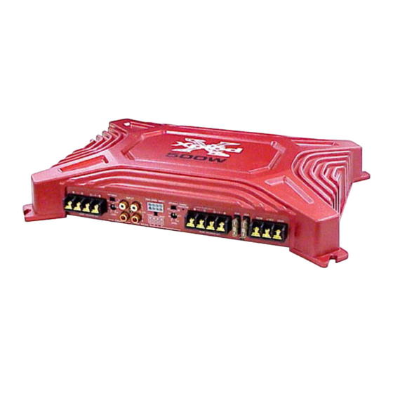
XM-504Z
SPECIFICATIONS
OTL (output transformerless) circuit
Pulse power supply
RCA pin jacks
High level input connector
0.3 – 6 V (RCA pin jacks),
0.6 – 12 V (High level input)
Speaker terminals
2 – 8 Ω (stereo)
4 – 8 Ω (when used as a bridging amplifier)
Four speakers: 100 W × 4 (at 4 Ω)
Three speakers: 100 W × 2 + 250 W × 1 (at 4 Ω)
Four speakers:
50 W × 4 (20 Hz – 20 kHz, 0.04% THD, at 4 Ω)
60 W × 4 (20 Hz – 20 kHz, 0.1% THD, at 2 Ω)
+0
5 Hz – 80 kHz (
dB)
–3
0.005% or less (at 1 kHz, 4 Ω, 10 W)
80 Hz, –18 dB/oct
80 Hz, –12 dB/oct
12 V DC car battery (negative ground)
10.5 – 16 V
at rated output : 30 A (4 Ω, 50 W × 4)
Remote input : 1 mA
Approx. 350 × 55 × 233 mm
× 2
× 9
(13
in.) (w/h/d)
7/8
1/4
1/4
not incl. projecting parts and controls
Approx. 3.1 kg (6 lb. 14 oz.) not incl. accessories
Mounting screws (4)
High level input cord (1)
Protection cap (1)
STEREO POWER AMPLIFIER
US Model
Canadian Model
AEP Model
UK Model
E Model
1
Advertisement
Table of Contents

Related Manuals for Sony XM-504Z


Summary of Contents for Sony XM-504Z
-
Page 1: Service Manual
High level input cord (1) Protection cap (1) Design and specifications are subject to change without notice. STEREO POWER AMPLIFIER Sony Corporation 9-877-562-01 2004A04-1 e Vehicle Company © 2004. 01 Published by Sony Engineering Corporation Downloaded from www.Manualslib.com manuals search engine... -
Page 2: Table Of Contents
LES COMPOSANTS IDENTIFIÉS PAR UNE MARQUE 0 SUR LES DIAGRAMMES SCHÉMATIQUES ET LA LISTE DES PIÈCES SONT CRITIQUES POUR LA SÉCURITÉ DE FONCTIONNEMENT. NE REMPLACER CES COMPOSANTS QUE PAR DES PIÈCES SONY DONT LES NUMÉROS SONT DONNÉS DANS CE MANUEL OU DANS LES SUPPLÉMENTS PUBLIÉS PAR SONY. - Page 3 XM-504Z SECTION 1 GENERAL This section is extracted from instruction manual. Downloaded from www.Manualslib.com manuals search engine...
- Page 4 XM-504Z Downloaded from www.Manualslib.com manuals search engine...
-
Page 5: Disassembly
XM-504Z SECTION 2 DISASSEMBLY Note : This set can be disassemble according to the following sequence. 2-1. BOTTOM PLATE (Page 5) 2-2. MAIN BOARD SECTION (Page 6) 2-3. MAIN BOARD (Page 6) Note : Follow the disassembly procedure in the numerical order given. - Page 6 XM-504Z 2-2. MAIN BOARD SECTION 1 three screws (+BTP 3 x 8) 4 screw (+BTP 3 x 8) 2 three screws (+BTP 3 x 8) 3 three screws (+BTP 3 x 8) 5 MAIN board section After unfastening the screw, taping with the screw inserted facilitates the work.
-
Page 7: Diagrams
XM-504Z SECTION 3 DIAGRAMS THIS NOTE IS COMMON FOR PRINTED WIRING BOARDS AND SCHEMATIC DIAGRAMS. (In addition to this, the necessary note is printed in each block.) for schematic diagram: • All capacitors are in µF unless otherwise noted. pF: µµF 50 WV or less are not indicated except for electrolytics and tantalums. -
Page 8: Printed Wiring Board
XM-504Z 3-2. PRINTED WIRING BOARD • Refer to page 7 for Common Note on Printed Wiring Boards. MAIN BOARD D807 Q311 Q310 Q411 Q410 JW158 JW151 JW150 JW152 Q212 Q306 Q406 B C E B C E R267 E C B... -
Page 9: Schematic Diagram -Amp Section
XM-504Z 3-3. SCHEMATIC DIAGRAM — AMP SECTION — • Refer to page 7 for Common Note on Schematic Diagrams. R159 R158 R175 D101 R155 Q108 Q104 R170 Q103 C152 Q110 R165 Q112 R167 R177 Q107 C151 C153 R163 Q101 IC801(1/2) -
Page 10: Schematic Diagram -Power Section
XM-504Z 3-4. SCHEMATIC DIAGRAM — POWER SECTION — • Refer to page 7 for IC Block Diagram and Common Note on Schematic Diagrams. (Page 9) D807 R805 C805 Q807 Q803 T901 Q911 C819 D803 Q804 Q801 R810 R926 R923 Q908... -
Page 11: Exploded Views
XM-504Z SECTION 4 EXPLODED VIEWS NOTE: • The mechanical parts with no reference • Color Indication of Appearance Parts The components identified by mark 0 or dotted line with mark number in the exploded views are not supplied. Example : 0 are critical for safety. -
Page 12: Main Board Section
XM-504Z 4-2. MAIN BOARD SECTION not supplied not supplied not supplied Ref. No. Part No. Description Remark Ref. No. Part No. Description Remark A-3283-674-A MAIN BOARD, COMPLETE 7-685-546-14 SCREW +BTP 3X8 TYPE2 N-S 3-263-893-01 PANEL (FRONT) (US,CND,E,MX) 7-685-546-19 SCREW +BTP 3X8 TYPE2 N-S... -
Page 13: Electrical Parts List
XM-504Z SECTION 5 MAIN ELECTRICAL PARTS LIST NOTE: • Due to standardization, replacements in • SEMICONDUCTORS The components identified by mark 0 or dotted line with mark the parts list may be different from the In each case, u : µ, for example: 0 are critical for safety. - Page 14 XM-504Z MAIN Ref. No. Part No. Description Remark Ref. No. Part No. Description Remark C824 1-164-004-11 CERAMIC CHIP 0.1uF < IC > C825 1-164-004-11 CERAMIC CHIP 0.1uF C826 1-126-933-11 ELECT 100uF IC801 8-759-710-28 IC NJM4565M-A C827 1-126-933-11 ELECT 100uF IC802...
- Page 15 XM-504Z MAIN Ref. No. Part No. Description Remark Ref. No. Part No. Description Remark Q102 8-729-232-66 TRANSISTOR 2SA1618Y Q904 8-729-027-43 TRANSISTOR DTC114EKA-T146 Q103 8-729-014-86 TRANSISTOR 2SC4207-YGR-TE85L Q905 8-729-106-60 TRANSISTOR 2SB1115A Q104 8-729-140-82 TRANSISTOR 2SA988-PAFAEA Q906 8-729-120-28 TRANSISTOR 2SC1623-L5L6 Q105 8-729-140-84 TRANSISTOR 2SC1841-PAFAEA...
- Page 16 XM-504Z MAIN Ref. No. Part No. Description Remark Ref. No. Part No. Description Remark R209 1-216-084-00 METAL CHIP 1/10W R366 1-216-182-00 RES-CHIP 1/8W R210 1-216-073-00 RES-CHIP 1/10W R367 1-216-134-00 METAL CHIP 1/8W R211 1-216-073-00 RES-CHIP 1/10W R368 1-216-134-00 METAL CHIP...
-
Page 17: Connections
XM-504Z MAIN Ref. No. Part No. Description Remark Ref. No. Part No. Description Remark R811 1-216-049-11 RES-CHIP 1/10W MISCELLANEOUS R814 1-216-210-00 RES-CHIP 3.3K 1/8W *************** R815 1-216-210-00 RES-CHIP 3.3K 1/8W R901 1-216-065-00 RES-CHIP 4.7K 1/10W 0 F901 1-576-256-11 FUSE (BLADE TYPE) (AUTO FUSE) (25A) - Page 18 XM-504Z REVISION HISTORY Clicking the version allows you to jump to the revised page. Also, clicking the version at the upper right on the revised page allows you to jump to the next revised page. Ver. Date Description of Revision 2004.
Need help?
Do you have a question about the XM-504Z and is the answer not in the manual?
Questions and answers