Table of Contents
Advertisement
Quick Links
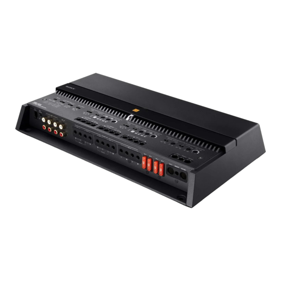
5-Channel Power
Amplifier
Owner's Record
The model and serial numbers are located on the bottom of the unit.
Record the serial number in the space provided below.
Refer to these numbers whenever you call upon your Sony dealer
regarding this product.
Model No. XM-5ES
Serial No.
XM-5ES
5-038-864-11(1)
Operating Instructions
Mode d'emploi
Bedienungsanleitung
Manual de instrucciones
Gebruiksaanwijzing
Bruksanvisning
GB
FR
DE
ES
NL
SE
Advertisement
Table of Contents

Related Manuals for Sony XM-5ES


Summary of Contents for Sony XM-5ES
- Page 1 Owner’s Record The model and serial numbers are located on the bottom of the unit. Record the serial number in the space provided below. Refer to these numbers whenever you call upon your Sony dealer regarding this product. Model No. XM-5ES Serial No.
- Page 2 Sony over these products at end-of-life to the Belgium, bijkantoor van Sony Europe B.V., Da appropriate collection point for the recycling of Vincilaan 7-D1, 1930 Zaventem, Belgium. electrical and electronic equipment.
- Page 3 Features • Rated power output of 100 W (at 4 Ω) and 165 W (at 2 Ω). • Class D Technology* • Dynamic Distortion Suppressor* • Active Thermal Control* • For car audio units without a line output, direct connection (High Level Input Connection) to the speaker output of your car audio unit can be made using a speaker-wire-to-RCA adaptor (not supplied).
-
Page 4: Table Of Contents
Table of Contents Features ........3 Guide to Parts and Controls Power Amplifier. -
Page 5: Guide To Parts And Controls
Guide to Parts and Controls Power Amplifier Control Panel (Top Panel) CH 1/2 CH 3/4 SUB CH LPF (Hz) TURN-ON INPUT MODE LINE OUT MODE FILTER RANGE ( Hz) HPF ( Hz) LPF ( Hz) INPUT SENS FILTER RANGE ( Hz) HPF ( Hz) LPF ( Hz) INPUT SENS... - Page 6 INPUT MODE section: CH 1/2 and CH 3/4 section: CH 1-4 switch FILTER switch Selects the input mode for CH 1, CH 2, CH 3 and Sets the filter mode for CH 1/2 and CH 3/4. CH 4. •...
-
Page 7: Bass Remote
Connector Panel (Front Panel) INPUT BASS INPUT LINE OUT SPEAKER OUT 40 A 40 A 40 A 40 A 12 V REMOTE GROUND REMOTE VOLTAGE CH 1 CH 2 CH 3 CH 4 SUB CH LOW HIGH BRIDGED BRIDGED BASS REMOTE connector ... -
Page 8: Installation And Connection
Installation Installation and Connection Installing the Amplifier Parts for Installation and Connection • Mount the amplifier either inside the trunk (boot) or under a seat. Mounting screw Mounting bracket (1) • For your safety, choose a mounting location that (5 ×... - Page 9 Changing the heat sink cover direction Installing the Bass Remote The direction of the heat sink cover can be changed according to your preference. • Do not install the bass remote near a heater, in areas that get exposed to direct sunlight or in Slide the cover forward, then lift to remove areas subject to high temperature.
-
Page 10: Connection
Mount the bass remote to your selected Connection mounting location with the mounting screws . • Before making any connections, disconnect the ground (earth) terminal of the car battery to avoid short circuits. Connect this amplifier to the +12 V power supply lead only after all other leads have been connected. - Page 11 GROUND terminal Power Connections • Be sure to connect the ground (earth) lead securely to a metal point on the car chassis. A +12 V REMOTE loose connection may cause the amplifier to malfunction. GROUND • During full-power operation, a current of more than 160 A will run through the system.
- Page 12 The following shows the connection and settings Input Connection typically used when connecting a car audio unit and this amplifier. Refer to the operating instructions The INPUT connector can be used by both low-level supplied with your car audio for more details about input and high-level input.
- Page 13 6-channel input 2-channel input With “Speaker Connection” (page 14) or . With “Speaker Connection” (page 14) or . AUDIO OUT FRONT REAR INPUT MODE AUDIO AUDIO CH 1-4 SUB CH * Use a speaker wire-to-RCA adaptor (not supplied) for high- level input connection.
- Page 14 3-channel input Speaker Connection With “Speaker Connection” (page 14) or . • Be sure to use speakers with an adequate power rating. If you use small capacity speakers, they may be damaged. • Do not connect any active speakers (with built-in amplifiers) to the speaker terminals of the AUDIO amplifier.
- Page 15 4 speaker + 1 subwoofer system 2 bridged speaker + 1 subwoofer With “Input Connection” (page 12) , , , , system or . With “Input Connection” (page 12) . Front speaker (min. 4 Ω) Full range speaker (min. 2 Ω) Rear speaker (min.
-
Page 16: Additional Information
If this this could damage the amplifier. unit has overheated, wait until it cools down before use. If you have any questions or problems concerning your unit that are not covered in this Operating Instruction, consult your nearest Sony dealer. -
Page 17: Specifications
Current drain: Specifications At rated output: 30 A (4 Ω, 100 W × 4) 80 A (2 Ω, 750 W × 1) FOR THE CUSTOMERS IN THE USA. Remote input: 4 mA POUR LES CLIENTS AUX ÉTATS-UNIS. Dimensions: Approx. 380 mm × 60 mm × 215 mm (15 in × AUDIO POWER SPECIFICATIONS in ×... -
Page 18: Troubleshooting
Please refer to the connection and If these solutions do not help improve the situation, operating procedures before going through the consult your nearest Sony dealer. checklist below. The status indicator light does not light up. The fuse is blown. - Page 19 ©2022 Sony Corporation Printed in Thailand https://www.sony.net/...
Need help?
Do you have a question about the XM-5ES and is the answer not in the manual?
Questions and answers