Table of Contents
Advertisement
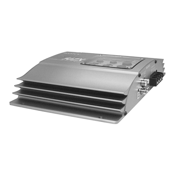
SERVICE MANUAL
Ver 1.1 2001. 08
Circuit system
OTL (output transformerless) circuit
Pulse power supply
Inputs
RCA pin jacks
High level input connector
Outputs
Speaker terminals
Through out pin jacks
Speaker impedance
2 - 8 ohms (stereo)
4 - 8 ohms (when used as a bridging
amplifier)
Maximum outputs
100 watts per channel (at 4 ohms)
260 watts (monaural) at 4 ohms
Rated outputs (supply voltage at 14.4 V)
50 watts per channel (20 Hz -
20 kHz, 0.04 % THD, at 4 ohms)
65 watts per channel (20 Hz -
20 kHz, 0.1 % THD, at 2 ohms)
130 watts (monaural) (20 Hz -
20 kHz, 0.1 % THD, at 4 ohms)
Frequency response
5 Hz - 100 kHz ( dB)
Harmonic distortion
0.005 % or less
(at 1 kHz, 4 ohms)
Input level adjustment range
0.2 - 4.0 V (RCA pin jacks)
0.4 - 8.0 V (High level input)
Sony Corporation
9-925-591-12
2001H0400-1
e Vehicle Company
© 2001. 8
Shinagawa Tec Service Manual Production Group
SPECIFICATIONS
+0
–3
XM-502X
High-pass filter
50 - 200 Hz, –12 dB/oct
Low-pass filter
50 - 200 Hz, –12 dB/oct
Low boost
0 - 10 dB (40 Hz)
Power requirements
12 V DC car battery
(negative ground)
Power supply voltage
10.5 - 16 V
Current drain
at rated output: 15 A
Remote input: 2 mA
Approx. 258 × 55 × 182 mm
Dimensions
× 2
× 7
(10
1/4
3/8
(l/h/p) not incl. projecting parts and
controls
Mass
Approx. 1.9 kg (4 lb. 3 oz.)
not incl. accessories
Supplied accessories
Mounting screws (4)
High level input cord (1)
Protect cover (1)
Design and specifications are subject to change without
notice.
STEREO POWER AMPLIFIER
US Model
Canadian Model
AEP Model
UK Model
E Model
in.)
1/4
Advertisement
Table of Contents

Related Manuals for Sony XM-502X


Summary of Contents for Sony XM-502X
- Page 1 XM-502X SERVICE MANUAL US Model Canadian Model Ver 1.1 2001. 08 AEP Model UK Model E Model SPECIFICATIONS Circuit system OTL (output transformerless) circuit High-pass filter 50 - 200 Hz, –12 dB/oct Pulse power supply Low-pass filter 50 - 200 Hz, –12 dB/oct...
-
Page 2: Table Of Contents
TABLE OF CONTENTS 1. GENERAL Location and Function of Controls ......... 3 Connections ................4 2. DISASSEMBLY 2-1. Bottom Plate ............... 6 2-2. Panel (Front) ............... 6 2-3. Amplifier Board ..............7 2-4. Filter Board ................ 7 3. DIAGRAMS 3-1. Block Diagram ..............8 3-2. - Page 3 SECTION 1 GENERAL This section extracted from instruction manual. – 3 –...
- Page 4 – 4 –...
- Page 5 – 5 –...
-
Page 6: Bottom Plate
SECTION 2 DISASSEMBLY Note : Follow the disassembly procedure in the numerical order given. 2-1. BOTTOM PLATE 3 bottom plate 2 BTP 3x6 1 BTP 3x6 2-2. PANEL (FRONT) 2 BTP 3x8 1 fuse (25 A) 4 panel (front) 3 BTP 3x8 –... -
Page 7: Amplifier Board
2-3. AMPLIFIER BOARD 2 BTP 3x8 5 BTP 3x5 3 BTP 3x10 4 BTP 3x10 1 BTP 3x8 6 AMPLIFIER board connectors 2-4. FILTER BOARD 3 FILTER board 2 BTP 3x5 1 BTP 3x5 – 7 –... -
Page 11: Amplifier Board Section
SECTION 4 EXPLODED VIEWS NOTE: • The mechanical parts with no reference • Hardware (# mark) list and accessories • -XX and -X mean standardized parts, so number in the exploded views are not supplied. they may have some difference from the and packing materials are given in the •... -
Page 12: Filter Board Section
4-2. FILTER BOARD SECTION D916 Ref. No. Part No. Description Remark Ref. No. Part No. Description Remark 3-012-826-01 COVER * 58 3-014-400-01 CASE (UPPER), LED MODULE 3-013-266-01 SCREW, ORNAMENT * 59 3-014-401-01 CASE (LOWER), LED MODULE * 53 3-012-827-01 FRAME, ORNAMENT 3-012-831-01 KNOB (SWA) 3-012-397-01 PLATE, ORNAMENTAL 3-012-832-01 KNOB (SWB) -
Page 13: Electrical Parts List
SECTION 5 AMPLIFIER ELECTRICAL PARTS LIST NOTE: • Due to standardization, replacements in • Items marked “*” are not stocked since When indicating parts by reference the parts list may be different from the they are seldom required for routine service. number, please include the board. - Page 14 AMPLIFIER Ref. No. Part No. Description Remark Ref. No. Part No. Description Remark D902 8-719-109-97 DIODE RD6.8ES-B2 Q108 8-729-207-82 TRANSISTOR 2SC3421-Y D903 8-719-801-78 DIODE 1SS184 Q109 8-729-207-89 TRANSISTOR 2SA1358-Y D904 8-719-801-78 DIODE 1SS184 Q110 8-729-024-80 TRANSISTOR 2SC5100-Y D905 8-719-054-55 DIODE 1SS306(TE85L) Q111 8-729-024-77 TRANSISTOR 2SA1908-Y D906...
- Page 15 AMPLIFIER Ref. No. Part No. Description Remark Ref. No. Part No. Description Remark R137 1-249-539-11 CARBON 1/4W R906 1-216-202-00 METAL GLAZE 1.5K 1/8W R138 1-247-712-11 CARBON 1/4W R907 1-216-210-00 METAL GLAZE 3.3K 1/8W R139 1-249-538-11 CARBON 1/4W R908 1-216-079-00 METAL CHIP 1/10W R140 1-249-568-11 CARBON...
- Page 16 FILTER Ref. No. Part No. Description Remark Ref. No. Part No. Description Remark A-3313-124-A FILTER BOARD, COMPLETE < JUMPER RESISTOR > ********************** JR901 1-216-295-00 CONDUCTOR, CHIP (2012) 3-014-400-01 CASE (UPPER), LED MODULE JR902 1-216-295-00 CONDUCTOR, CHIP (2012) 3-014-401-01 CASE (LOWER), LED MODULE JR903 1-216-295-00 CONDUCTOR, CHIP (2012)
- Page 17 Ver 1.1 FILTER Ref. No. Part No. Description Remark Ref. No. Part No. Description Remark R117 1-216-097-00 METAL GLAZE 100K 1/10W < SWITCH > R118 1-216-061-00 METAL CHIP 3.3K 1/10W R119 1-216-073-00 METAL CHIP 1/10W S101 1-771-159-11 SWITCH, SLIDE (FILTER) R120 1-216-061-00 METAL CHIP 3.3K...
- Page 18 XM-502X Ref. No. Part No. Description Remark ************** HARDWARE LIST ************** 7-685-546-19 SCREW +BTP 3X8 TYPE 2 N-S 7-685-545-11 SCREW +BTP 3X6 TYPE 2 N-S 7-682-949-01 SCREW +PSW 3X10 7-685-544-11 SCREW +BTP 3X5 TYPE 2 N-S 7-685-547-11 SCREW +BTP 3X10 TYPE 2 N-S 7-685-792-01 SCREW +PTT 2.6X6 (S)
- Page 19 File this supplement with the service manual. Subject: Red Color Panal Addition (AEP/UK model) The difference parts are described in this service manual supplement-1. Please refer to XM-502X service manual previously issued for the other information. • DIFFERENCE PARTS LIST Page Former Ref.
- Page 20 XM-502X REVISION HISTORY Clicking the version allows you to jump to the revised page. Also, clicking the version at the upper on the revised page allows you to jump to the next revised page. Ver. Date Description of Revision 2001. 08 The CORRECTION-1 is included into Ver 1.1...
Need help?
Do you have a question about the XM-502X and is the answer not in the manual?
Questions and answers