Samson 3730-4 Mounting And Operating Instructions
Series 3730
electropneumatic positioner
Hide thumbs
Also See for 3730-4:
- Quick start manual ,
- Mounting and operating instructions (212 pages) ,
- Original instructions manual (128 pages)

Related Manuals for Samson 3730-4


Summary of Contents for Samson 3730-4
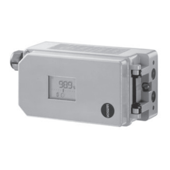
- Page 1 Series 3730 Electropneumatic Positioner Type 3730-4 with PROFIBUS-PA communication Fig. 1 · Type 3730-4 Mounting and Operating Instructions EB 8384-4 EN Firmware version K 1.12/R 1.45 Edition July 2008...
- Page 2 EB 8384-4 EN...
-
Page 3: Table Of Contents
Contents Contents Page Design and principle of operation ....9 Additional equipment ......10 Communication . - Page 4 Contents Checking the operating range of the positioner ... . . 50 Initialization ......52 5.6.1 Initialization modes .
- Page 5 Contents 13.1 General ....... 99 13.1.1 System requirements ......99 13.2 Installing TROVIS-VIEW software .
- Page 6 Modifications to positioner firmware Modifications to positioner firmware compared to the previous version Communication K 1.00 K 1.01 Internal modifications K 1.01 K 1.10 The FEATURE_SELECT parameter allows you to set whether an active diagnostic func- tion is to be reported by a GOOD_FUNCTION_CHECK or a BAD_FUNCTION_ CHECK (see page 144) K 1.10 K 1.11...
- Page 7 Safety instructions General safety instructions The positioner may only be mounted, started up or operated by trained and experienced personnel familiar with the product. According to these mounting and operating instructions, trained personnel refers to individuals who are able to judge the work they are assigned to and recognize possible dangers due to their specialized training, their knowledge and experience as well as their knowledge of the relevant standards.
- Page 8 Article code Positioner Type 3730-4 x x x 0 x 0 x x 1 x 0 0 x 0 x x With LCD and autotune, PROFIBUS-PA Explosion protection None II 2 G EEx ia IIC T6 and II 2 D IP 65 T 80 °C (ATEX)
-
Page 9: Design And Principle Of Operation
Design and principle of operation When a deviation occurs, the actuator is Design and principle of pressurized or vented. If required, the operation changes in the signal pressure can be slowed down by a connectable Q restric- The electropneumatic positioner is attached tion. -
Page 10: Additional Equipment
Design and principle of operation The positioner communicates and is pow- can also be issued over the PROFIBUS-PA ered using IEC 61158-2 transmission tech- network. nology conforming to PROFIBUS-PA specifi- Version with external position sensor cation. In this version, only the sensor is mounted to As a standard feature, the positioner comes the control valve. -
Page 11: Technical Data
DTM file acc. to Specification 1.2, suitable for integration of the device into frame- work applications that support the FDT/DTM concept. Other integrations, e.g. PDM, possible Local Over SAMSON SSP interface and serial interface adapter Software requirements (SSP) SAMSON TROVIS-VIEW with database module 3730-4 Perm. operating voltage 9 to 32 V DC, power supply over bus line ·... - Page 12 Design and principle of operation Type 3730-4 Positioner with PROFIBUS-PA communication Permissible ambient –40 to +80 °C temperature The limits in the EC Type Examination Certificate additionally apply for explosion-pro- tected devices Temperature: ≤ 0.15 %/10 K Influences Supply air: None Vibration: ≤...
- Page 13 Design and principle of operation Options for Type 3730-4 Positioner with PROFIBUS-PA communication Binary contact 2 for floating contact R < 100 Ω, contact load 100 mA, static destruction limit 20 V / 5.8 mA, Switching input galvanically isolated Solenoid valve Approval acc.
-
Page 14: Attachment To The Control Valve - Mounting Parts And Accessories
– Mounting parts and accessories The positioner can be attached either di- rectly to a SAMSON Type 3277 Actuator or according to IEC 60534-6 (NAMUR) to con- trol valves with cast yokes or rod-type yokes as well as to rotary actuators according to VDI/VDE 3845. - Page 15 Travel Max. lever pin position 3277 120/240/350 35.0 Actuators 10.0 50.0 Travel table for attachment according to IEC 60534-6 (NAMUR) SAMSON valves Other valves/actuators Required Assigned lever pin position cm² Rated travel mm Min. Travel Max. 60 and 120 with 18.0...
- Page 16 Attachment to the control valve – Mounting parts and accessories Table 1 Direct attachment to Type 3277-5 Actuator, see Fig. 4 Order no. Mounting parts For actuators with 120 cm² effective diaphragm area 1400-7452 Switchover plate (old) for Actuator Type 3277-5xxxxxx.00 (old) 1400-6819 Switchover plate new for Actuator Type 3277-5xxxxxx.01 (new) 1400-6822...
- Page 17 VDI/VDE 3845 for all sizes of fixing level 2, heavy-duty version 1400-9244 parts Mounting parts for rotary actuators VDI/VDE 3845 (level 1), heavy-duty version 1400-9526 SAMSON Type 3278 160 cm² / VETEC Type S160 and Type R, heavy-duty version 1400-9245 AIR TORQUE 10 000, heavy-duty version 1400-9542 Connecting plate G ¼: 1400-7461...
-
Page 18: Direct Attachment
Attachment to the control valve – Mounting parts and accessories Direct attachment ing towards the signal pressure connec- tion. Make sure that the bonded gasket 2.1.1 Type 3277-5 Actuator (14) points towards the actuator yoke. 5. 15 mm travel: Keep the follower pin (2) Refer to Table 1 on page 16 for the required at lever M (1) on the back of the mounting parts as well as the accessories... - Page 19 Attachment to the control valve – Mounting parts and accessories Symbols Lever Switchover plate (9) 1.1 Nut Actuator stem 1.2 Disk spring extends Follower pin Follower clamp Vent plug Attachment left Attachment right Stopper Connecting plate Actuator stem 6.1 Seal rings retracts Pressure gauge bracket Press.
-
Page 20: Type 3277 Actuator
Attachment to the control valve – Mounting parts and accessories 2.1.2 Type 3277 Actuator rests on the top of the follower clamp (3). Adjust the lever (1) correspondingly Refer to Table 2 on page 16 or the required and open the positioner cover to hold mounting parts as well as the accessories the positioner shaft in position at the cap with their order numbers. - Page 21 Attachment to the control valve – Mounting parts and accessories Lever 12.1 Screw 1.1 Nut 12.2 Stopper or connection for 1.2 Disk spring external piping Follower pin Switch plate 10 14 Follower clamp Gasket 10 Cover plate Formed seal 11 Cover Gasket 12 Connection block Lever M...
-
Page 22: Attachment According To Iec 60534-6
Attachment to the control valve – Mounting parts and accessories Attachment according to 4. Select required lever size (1) M, L or XL and pin position according to the actua- IEC 60534-6 tor size and valve travels listed in the ta- The positioner is attached to the control ble on page 15. - Page 23 Attachment to the control valve – Mounting parts and accessories Attachment to rod-type yoke Rod diameter 20 to 35 mm Attachment to NAMUR rib Additional bracket for actuators with 2800 cm and travel ≥ 60 mm Lever XL and L Lever 14.1 Disk spring...
-
Page 24: Attachment To Type 3510 Micro-Flow Valve
Attachment to the control valve – Mounting parts and accessories Attachment to Type 3510 Micro-flow Valve The positioner is attached to the valve yoke using a bracket. Refer to Table 3 on page 16 for the required mounting parts as well as the accessories with their order numbers. - Page 25 Attachment to the control valve – Mounting parts and accessories Lever Disk spring Follower pin Clamp Connecting plate Seal rings Pressure gauge bracket Pressure gauge mounting kit Bracket Screw Note! Always use the connecting plate (6) included in the accessories to connect supply and output.
-
Page 26: Attachment To Rotary Actuators
Prior to the attachment of the positioner to bore for pin position 90°. the SAMSON Type 3278 Rotary Actuator, 7. Place positioner on the top pair of you have to mount the associated adapter (5) to the free end of the rotary actuator brackets (10) and screw tight. - Page 27 Attachment to the control valve – Mounting parts and accessories (7, 8) 10.1 Note! Always use the connecting plate (6) included in the accessories to connect supply and output. Never screw threaded parts directly into the housing. Control valve opens counterclockwise Slot Legends Figs.
-
Page 28: Reversing Amplifier For Double-Acting Actuators
Attachment to the control valve – Mounting parts and accessories Reversing amplifier for Caution! double-acting actuators The sealing plug (1.5) in the Type 3730 Positioner should not be unscrewed out of For the use with double-acting actuators, the the reversing amplifier. positioner must be fitted with a reversing The rubber seal (1.4) is not required and amplifier. - Page 29 Attachment to the control valve – Mounting parts and accessories From the positioner Output 38 Supply 9 Control signals to the actuator Reversing amplifier Connecting plate 1.1 Special screws 6.1 O-rings 1.2 Gasket 6.2 Screws 1.3 Special nuts 1.4 Rubber seal 1.5 Sealing plug 1.6 Filter Fig.
-
Page 30: Attaching An External Position Sensor
Attachment to the control valve – Mounting parts and accessories Attaching an external position sensor Refer to Table 6 on page 35 for a list of the mounting parts as well as the accessories required for mounting the position sensor. Accessories for the pneumatic connection to the positioner housing can be found in Table 7. - Page 31 Attachment to the control valve – Mounting parts and accessories Type 3277 Actuator with 240 to 700 cm²: 2. Screw the position sensor (20) onto the mounting plate (21). The signal pressure is routed to the connec- 3. Depending on the actuator size and tion at the side of the actuator yoke for the rated travel of the valve, determine the version "Actuator stem extends".
-
Page 32: Mounting The Position Sensor With Attachment According To Iec 60534-6
Attachment to the control valve – Mounting parts and accessories 2.6.2 Mounting the position Place the lever (1) in mid-position and hold it in place. Screw on the nut (1.1). sensor with attachment 5. Place the follower clamp (3) on the actu- according to IEC 60534-6 ator stem, align and fasten it, making For the required mounting parts as well as... -
Page 33: Mounting The Position Sensor To Type 3510 Micro-Flow Valve
Attachment to the control valve – Mounting parts and accessories For other actuator sizes or travels, select the Place the lever (1) in mid-position and lever and pin position from the travel table hold it in place. Screw on the nut (1.1). on page 15. -
Page 34: Mounting The Position Sensor To Rotary Actuators
Attachment to the control valve – Mounting parts and accessories 2.6.4 Mounting the position 4. Place the lever (1) and disk spring (1.2) on the sensor shaft. sensor to rotary actuators Place the lever (1) in mid-position and For the required mounting parts as well as hold it in place. - Page 35 CrNiMo steel bracket, see Fig. 15 Attachment to rotary actuators VDI/VDE 3845 for all sizes of fixing level 2, heavy-duty version 1400-9384 SAMSON Type 3278 160 cm / VETEC Type S160 and Type R, heavy-duty 1400-9385 version Table 7 Positioner accessories Order no.
-
Page 36: Attaching Positioners With Stainless Steel Housings
Attachment to the control valve – Mounting parts and accessories Attaching positioners with Air purging function for stainless steel housings single-acting actuators Positioners with stainless steel housings re- The exhaust air from the positioner is di- quire mounting parts that are completely verted to the actuator spring chamber to made of stainless steel or free of aluminum. - Page 37 Attachment to the control valve – Mounting parts and accessories Should other valve accessories be used which vent the actuator (e.g. solenoid valve, volume booster, quick exhaust valve), this exhaust air must also be included in the purging function. The connection over the adapter at the positioner must be protected with a check valve (e.g.
-
Page 38: Connections
Connections Connections 3.1.1 Signal pressure gauges To monitor the supply air (Supply) and sig- Pneumatic connections nal pressure (Output), we recommend that pressure gauges be attached (see accesso- Caution! ries in Tables 1 to 5). The threads in the positioner housing are not designed for direct air connection! 3.1.2 Supply pressure The required supply air pressure depends... - Page 39 Connections d = Seat diameter [cm] Δp = Differential pressure across the valve [bar] A = Actuator diaphragm area [cm²] = Upper bench range of the actuator [bar] If there are no specifications, calculate as follows: Required supply pressure = Upper bench range value + 1 bar Note! The signal pressure at the output (Out-...
-
Page 40: Electrical Connections
Connections Electrical connections For the interconnection of equipment to en- ergy-limited circuits with type of protection For electrical installation, you are re- EEx nL IIC, the permissible maximum values quired to observe the relevant specified in the statement of conformity or electrotechnical regulations and the the addenda to the statement of conformity accident prevention regulations that... - Page 41 Connections nected over a large area to the gland and Note: The power supply for the positioner housing. can be supplied either over the connection to the fieldbus segment or over a DC voltage 1. To connect the bus line, loosen the gland source (9 to 32 V) connected to the bus ter- nut and the clamping insert from the minals in the positioner.
-
Page 42: Establishing Communication
Connections The positioner can report the switching state 5. Press the clamping insert into the con- over the bus protocol. necting screw gland and screw tight the gland nut until the connecting cable is Solenoid valve (forced venting function) clamped tightly. 6. - Page 43 Connections Controller/PLC/Control system PROFIBUS-DP(E) RS 485 (Master class 1) Display and operating elements (Master class 2) PROFIBUS-DP(E) RS 485 Bus termination Segment coupler PROFIBUS-PA IEC 61158-2 termination 3730-40 3730-40 3730-40 3730-40 Controller/PLC/Control system PROFIBUS-DP RS 485 Display and operating (Master class 1) elements PROFIBUS-DP RS 485 (Master class 2)
-
Page 44: Operation
Operation Volume restriction Q Operation The volume restriction is used to adapt the air delivery to the actuator size. Two fixed Note: A summary about operating and start settings are possible depending on how the up can be found in section 8 on page 69. air is routed at the actuator: For actuators smaller than 240 cm²... - Page 45 Operation Readings on the display and their meaning AUtO Automatic mode Start blinking Emergency mode Clockwise SAFE Fail-safe position (error code 62 Counterclockwise Substitute calibration x signal, see p. 123) Error TunE Initialization in progress Escape Available blinking Not initialized w too small Zero calibration Manual mode...
-
Page 46: Enabling And Selecting Parameters
Operation Enabling and selecting Important! parameters To cancel a value that you have just entered under a code, turn the button until ESC The codes which are marked with an aster- appears on the display and press to con- isk (*) in section 14.1 on page 110 onwards firm. -
Page 47: Operating Modes
Operation Switching to manual operating mode Operating modes Over Code 0 , press the button, AUtO 4.3.1 Automatic and manual appears in the display, Code 0 blinks. operating modes Turn button until MAN appears. Prior to initialization: If the positioner has not been initialized yet, the automatic operating AUtO cannot be se- lected. -
Page 48: Safe - Fail-Safe Position
Start-up and settings 4.3.2 SAFE – Fail-safe position Start-up and settings If you want to move the valve to fail-safe po- Note: A summary about start-up and opera- sition, proceed as follows: tion can be found in section 8 on page 69. Select Code 0 , press the button, AUtO or MAN appears on the display, Code 0... -
Page 49: Determining The Fail-Safe Position
AIR TO OPEN or AIR TO CLOSE . at the actuator in SAMSON actuators: AIR TO OPEN = Signal pressure opens the The “SIDE“ position applies for actuators... -
Page 50: Adapting The Display
Start-up and settings Adapting the display Checking the operating range of the positioner The data representation on the positioner display can be turned by 180°. To check the mechanical attachment and the If the displayed data appear upside down, proper functioning, the valve should be proceed as follows: moved through the operating range of the positioner in the manual operating mode... - Page 51 Start-up and settings ceeded when the displayed angle is higher than 30°, and the outer right or left bar graph element blinks. If this is the case, it is absolutely neces- sary to check lever and pin position as described in section 2. Note: If the selected pin position is smaller than intended for the respective travel range and exceeds 30°, the positioner switches to...
-
Page 52: Initialization
Start-up and settings Simplified start-up! For most applications, the positioner with its default settings is ready for operation, provided it has been properly attached. After the fail-safe position and the volume restriction have been set, the positioner only needs to be initialized by pressing the INIT key. Caution! Prior to starting the initialization procedure, check the maximum permissible supply pressure of the control valve to prevent the valve from being damaged. - Page 53 Start-up and settings Positioners with EXPERT diagnostic func- dicated by the closed-loop operation tions start plotting the reference graphs after icon. the initialization process has been com- The control position in % predetermined by pleted. See note at the end of this section. the reference variable appears on the dis- play.
-
Page 54: Initialization Modes
Start-up and settings → Code 3 , press An unsuccessful plotting of the reference Turn graphs is indicated on the display by Code → ON , press turn 81 (see error code list). After enabling: After the initialization has been successfully completed, the positioner still works prop- erly, even though the reference graph plot- ting has not been completed successfully. - Page 55 Start-up and settings → Code 4 , press Turn Enable configuration: → Select pin position determined on turn attachment, press Default OFF If you now switch to Code 5 , the nominal range appears in mm/°. The lower and upper x-range values for Code 8 and 9 are displayed in mm/°...
- Page 56 Start-up and settings Enable configuration: Press INIT key to start initialization! The initialization procedure may Default OFF take several minutes, depending on the actuator size, as the valve moves through its entire travel/angle of ro- → Code 3 , press Turn tation range.
- Page 57 Start-up and settings Turn until the valve reaches its OPEN po- usually fixed mechanically in a certain posi- sition, press tion, or pneumatically by means of a pres- sure signal which is routed to the actuator Press INIT key to start initialization! externally.
- Page 58 Start-up and settings Enable configuration: Default ää Default OFF → Code 7 , press Turn → Retain direction of action ää or → Code 3 , press turn Turn select äæ. → ON , press turn Press After enabling: Default 100.0 Default OFF →...
- Page 59 Start-up and settings → Select K turn Set switch for fail-safe position AIR TO OPEN or AIR TO CLOSE as described in press section 5.1 on page 49. Set volume restriction as described in section 5.2 on page 49. Press INIT key! Default 2 The positioner switches to manual operat- ing mode!
-
Page 60: Fault/Failure
Start-up and settings The positioner switches to automatic oper- Condensed status Display ating mode! Maintenance alarm The current valve position is indicated in %. Maintenance required/ Maintenance demanded Function check Text Note: If the positioner shows a tendency to oscillate in automatic operating mode, the No message parameters K and T... -
Page 61: Zero Calibration
Start-up and settings leaves the permissible temperature range af- fect the condensed state and cause a fault alarm to be displayed depending on its clas- Default MAX sification. The optional EXPERT diagnostics generates additional diagnostic alarms which are in- → Code 6 , press Turn cluded in the condensed status with their →... -
Page 62: Start-Up Via Local Interface (Ssp)
Fieldbus configuration or operating system, or TROVIS-VIEW operator interface con- nected over the serial interface in the Default 126 positioner. Use the TROVIS-VIEW software with 3730-4 device module installed. → Code 46 , press Turn To connect the positioner directly to the PC →... - Page 63 Start-up and settings der Code 46 in alternating sequence with the current address. The new address is marked with “n“ (new) and the currently used address with “o“ (old). Note: The bus address can only be imple- mented by the PROFIBUS command SET_ADRESS when the bus address is set to the default setting [126].
-
Page 64: Status And Diagnostic Alarms
Status and diagnostic alarms Status and diagnostic Extended EXPERT alarms diagnostics The Type 3730-4 Positioner contains inte- In addition to the standard EXPERT diagnos- grated diagnostics to generate classified sta- tic features, the optional EXPERT extended tus and diagnostic alarms. -
Page 65: Classification Of The Status Alarms And The Condensed Status
Status and diagnostic alarms The required reference graphs are automati- been assigned to, these are entered in cally plotted after initialization and saved in DIAGNOSIS_EXT_1_RAW and the positioner if EXPERT is activated. DIAGNOSIS_EXT_2_RAW parameters. The optional diagnostic functions provided The following states can be selected (refer to by EXPERT can be selected when ordering Fig. - Page 66 Status and diagnostic alarms The table below containing the condensed Logging and displaying diagnostic state is reached from the summary of active functions/alarms alarms. The last 30 alarms are logged in the Status modification positioner. An alarm that is repeated is only logged when it first occurs.
- Page 67 Status and diagnostic alarms Fig. 20 · Status and diagnostic alarms EB 8384-4 EN...
-
Page 68: Adjusting The Limit Switch
Adjusting the limit switch The desired switching function, i.e. whether Adjusting the limit switch the output relay shall be picked up or re- The positioner version with an inductive limit leased when the tag has entered the field, switch has one adjustable tag (1) mounted has to be determined, if necessary, at the on the shaft which operates the proximity switching amplifier. -
Page 69: Quick Start-Up Guide
1. Initialize positioner. Mounting 2. Use the MAN function to move the positioner to 5 % (see LC display). Direct attachment to SAMSON Type 3277 3. Adjust the tag using the yellow adjust- Actuator ment screw (2) until the tag enters or... -
Page 70: Start-Up
Quick start-up guide pin is in the slot of the follower plate. Start-up Make sure the lever can still move. Connect pneumatic supply air (1.4 to 6 bar). Attachment to rotary actuators Route the two-wire bus line to the screw Lever M pin position 90°... -
Page 71: Initialization
Quick start-up guide Operation Initialization Selecting the parameters or values Important! Each parameter has a code number which Perform a reset (Code 36) prior to each ini- is shown in the display. tialization Turn the button to select parameters or values and then push to confirm. -
Page 72: Manual Method (Man)
Quick start-up guide → Code 4 , ↵ turn → Select pin position, ↵ turn → Code 5 , ↵ turn → Enter nominal travel/range, ↵ turn → Code 6 , ↵ turn select NOM , ↵ Press INIT key! 8.3.3 Manual method (MAN) Initialization mode same as NOM , but for start-up of control valves with unknown... -
Page 73: Retrofitting An Inductive Limit Switch
Retrofitting an inductive limit switch Retrofitting an inductive limit switch Required retrofit kit: Limit switch Order no. 1400-7460 Note! For explosion-protected devices, the requirements in section 11 need to be kept. 1. Take off the rotary pushbutton (3) and cap (1), unthread the five fixing screws (2) and lift off the plastic cover (9). -
Page 74: Maintenance
Maintenance Maintenance Servicing explosion- protected devices The positioner does not require any mainte- nance. If a part of the positioner on which the ex- plosion protection is based needs to be ser- There are filters with a 100 μm mesh size in viced, the positioner must not be put back the pneumatic connections for supply and into operation until an expert has inspected... -
Page 75: Profibus-Pa Communication
Basic device functions have been described in profiles by PNO (PROFIBUS user organiza- tion) to supplement the EN 50170 standard. The scope of functions of the Type 3730-4 Positioner is consistent with Profile 3.01 with the extension “Condensed status and diagnostic messages V1.0”. -
Page 76: Gsd Files
Refer to section 12.4 for measured value status. 12.2.1 GSD files The GSD (device database) file (SAMS071D.gsd) is used to integrate the SAMSON Type 3730-4 Positioner with PROFIBUS-PA communication into the programming and configurati- on environment of the master class 1 in standardized form. This GSD file contains defined data required for cyclic data exchange. -
Page 77: Data Exchange
PROFIBUS-PA communication 12.2.2 Data exchange The relationship between output and input is based on the control system/master class 1. SLOT 1 Version 1: Module = SP 0x4A or 0x82, 0x84, 0x08, 0x05 Output Byte 0 Octet 1 Octet 2 Octet 3 Octet 4 Octet 5 Sign,... - Page 78 PROFIBUS-PA communication Version 3: Module = SP, READBACK + POS_D 0xC6, 0x84, 0x86, 0x08, 0x05, 0x08, 0x05, 0x05, 0x05 Output Byte 0 Octet 1 Octet 2 Octet 3 Octet 4 Octet 5 Sign, Exponent Exponent Fraction Fraction Fraction Fraction SP, value Status (Floating Point, IEEE) Input...
- Page 79 PROFIBUS-PA communication Version 5: Module = SP, READBACK + POS_D + CHECKBACK 0xC7, 0x84, 0x89, 0x08, 0x05, 0x08, 0x05, 0x05, 0x05, 0x0A Output Byte 0 Octet 1 Octet 2 Octet 3 Octet 4 Octet 5 Sign, Exponent Exponent Fraction Fraction Fraction Fraction SP, value...
- Page 80 PROFIBUS-PA communication Version 7: Module = SP + RCAS_IN, READBACK + RCAS_OUT + POS_D + CHECKBACK 0xCB, 0x89, 0x8E, 0x08, 0x05, 0x08, 0x05, 0x08, 0x05, 0x08, 0x05, 0x05, 0x05, 0x0A Output Byte 0 Octet 1 Octet 2 Octet 3 Octet 4 Octet 5 Octet 1 Octet 2...
-
Page 81: Integration For Pcs7 Control System
PROFIBUS-PA communication 12.2.3 Integration for PCS7 control system The following steps must be observed on integrating the positioner into a Simatic S7 control system to ensure that the positioner functions properly: 1. The module in Slot 1 can be read out over the function component SFC 14 “DPRD_DAT“ and, for example, assigned to a data module. - Page 82 PROFIBUS-PA communication Byte Bit Name Description CB_OVERRIDE Operating voltage for the optional built-in solenoid valve failed: The positioner cannot function and moves to the fail-safe position determined by the actuator, regardless of the reference variable. 4…6 Not assigned CB_TRAVE_TIME Control loop error: The control valve no longer follows the controlled variable in the tolerable times (see error code 57 on page 122).
-
Page 83: Status Coding Of Measured Values
PROFIBUS-PA communication Byte Bit Name Description CB_TOT_VALVE_TRAV Limit value for total valve travel exceeded: The current value for the total valve travel is above the entered or predetermined limit. Reset over SELF_CALIB_CMD = 10 (Reset Total valve travel limit exceeded). CB_ADD_INPUT Status of the second optional integrated binary input: The use of the second binary input must be configured... - Page 84 PROFIBUS-PA communication Fault/diagnostic alarm Value (hex) Status alarm acc. to Profile 3.01 Initialization errors x > range GOOD_NON_SPECIFIC 0x80 Delta x < range GOOD_NON_SPECIFIC 0x80 Incorrect attachment (mechanics/pneumatics) GOOD_NON_SPECIFIC 0x80 Initialization time exceeded GOOD_NON_SPECIFIC 0x80 Initialization/solenoid valve GOOD_NON_SPECIFIC 0x80 Transit time too short 0x80 GOOD_NON_SPECIFIC Pin position...
- Page 85 PROFIBUS-PA communication Fault/diagnostic alarm Value (hex) Status alarm acc. to Profile 3.01 Extended diagnostics – EXPERT Air supply Perhaps modified TEST GOOD_NON_SPECIFIC 0x80 Perhaps not enough TEST 0x80 GOOD_NON_SPECIFIC Perhaps not enough 0x80 GOOD_NON_SPECIFIC Working at full capacity 0x80 GOOD_NON_SPECIFIC Working at full capacity TEST 0x80 GOOD_NON_SPECIFIC...
- Page 86 PROFIBUS-PA communication Fault/diagnostic alarm Value (hex) Status alarm acc. to Profile 3.01 Perhaps too large GOOD_NON_SPECIFIC 0x80 Limit range Down GOOD_NON_SPECIFIC 0x80 GOOD_NON_SPECIFIC 0x80 Modification impossible GOOD_NON_SPECIFIC 0x80 Dynamic stress factor Load factor > 90 % GOOD_NON_SPECIFIC 0x80 Inner leakage Perhaps existing 0x80 GOOD_NON_SPECIFIC...
-
Page 87: Status Alarms According To Profile 3.01 Condensed Status
PROFIBUS-PA communication Fault/diagnostic alarm Value (hex) Status alarm acc. to Profile 3.01 Range Mostly near closing position GOOD_NON_SPECIFIC 0x80 Mostly near max. opening GOOD_NON_SPECIFIC 0x80 Mostly closing position GOOD_NON_SPECIFIC 0x80 Mostly max. opening GOOD_NON_SPECIFIC 0x80 Temperature monitoring Lower limit exceeded GOOD_NON_SPECIFIC 0x80 Higher limit exceeded... - Page 88 PROFIBUS-PA communication Classified Default setting acc. to Profile Fault/diagnostic alarm Diagnosis 3.01 Condensed Status DIA_MAINTENANCE Extended diagnostics available 0x80 GOOD_NON_SPECIFIC • EXTENSION_AVAILABLE No emergency mode 0xA4 GOOD_MAINT_REQ DIA_MEM_CHECKSUM • Temperature < –40 °C 0x80 GOOD_NON_SPECIFIC – • Temperature > 80 °C 0x80 GOOD_NON_SPECIFIC –...
- Page 89 PROFIBUS-PA communication Classified Default setting acc. to Profile Fault/diagnostic alarm Diagnosis 3.01 Condensed Status PA parameter 0xA4 GOOD_MAINT_REQ DIA_MEM_CHECKSUM • Diagnostic parameter 0xA4 GOOD_MAINT_REQ • DIA_MEM_CHECKSUM Extended diagnostics EXPERT Air supply Perhaps modified TEST 0x80 GOOD_NON_SPECIFIC • – Perhaps not enough TEST 0x80 GOOD_NON_SPECIFIC •...
- Page 90 PROFIBUS-PA communication Classified Default setting acc. to Profile Fault/diagnostic alarm Diagnosis 3.01 Condensed Status Leakage pneumatics Perhaps existing TEST 0x80 GOOD_NON_SPECIFIC • – Perhaps existing 0x80 GOOD_NON_SPECIFIC • – Perhaps too large TEST 0x80 GOOD_NON_SPECIFIC • – Perhaps too large 0x80 GOOD_NON_SPECIFIC •...
- Page 91 PROFIBUS-PA communication Classified Default setting acc. to Profile Fault/diagnostic alarm Diagnosis 3.01 Condensed Status Zero point alternating, average value 0x80 GOOD_NON_SPECIFIC • – below reference lines Connection positioner/valve No opt. travel transm. TEST 0x80 GOOD_NON_SPECIFIC • – Perhaps loose 0x80 GOOD_NON_SPECIFIC –...
-
Page 92: Diagnostics With Profibus-Dp Protocol
If, however, the DIAG.ext bit is set to 0, the existing data are treated as status information by the system. For the Type 3730-4 Positioner, this behavior can be determined by the FEATURE_SELECT parameter. By selecting the option “DIA_MAINTENANCE_ALARM sets DIAG_EXT bit“, the DIAG_EXT bit is set when the DIA_MAINTENANCE_ALARM bit has been... - Page 93 PROFIBUS-PA communication The first four bytes of the manufacturer-specific diagnosis are used for diagnostic alarms ac- cording to Profile 3.01. On using the “Condensed Status and diagnostic messages“ exten- sion, these condensed diagnostic alarms are also included in these bytes. The manufac- turer-specific diagnosis listed in the table below is transmitted in the eleventh byte and above.
- Page 94 PROFIBUS-PA communication Explanation Octet Note DIA_ZERO_ERR (zero point error, final position) – DIA_CONF_INVAL (configuration invalid/invalid address) DIA_WARMSTART (restart-up/warm start performed) DIA_COLDSTART (new start-up/cold start performed) DIA_MAINTENANCE (maintenance required) DIA_CHARACT (characteristic invalid) IDENT_NUMBER_VIOLATION (selected ID no. has not been implemented by the device yet) DIA_MAINTENANCE_ALARM (device error exists) DIA_MAINTENANCE_DEMANDED (maintenance demanded) DIA_FUNCTION_CHECK (device in function check, in simulation or in MODE_LO)
- Page 95 PROFIBUS-PA communication Explanation Octet Note Test or calibration running x signal (see Code 62) i/p converter (see Code 64) Hardware (see Code 65) Control parameter (see Code 68) Poti parameter (see Code 69) Adjustment parameter (see Code 70) Internal device error 1 (see Code 73) General parameter (see Code 71) No emergency mode (see Code 76) Program load error (see Code 77)
- Page 96 PROFIBUS-PA communication Explanation Octet Note Actuator spring: Perhaps pretensioning increased (TEST) Actuator spring: Working at full capacity Actuator spring: Working at full capacity (TEST) Shifting working range: Close Shifting working range: Open Friction: Higher over whole range Friction: Lower over whole range Friction: Higher over partial range Friction: Lower over partial range Friction: Higher whole range (TEST)
- Page 97 PROFIBUS-PA communication Explanation Octet Note Zero point shift monotonously downwards, average value below reference lines Zero point shift monotonously upwards, average value below reference lines Zero point shift alternating, average value below reference lines Attachment between positioner and valve: Travel transmission not optimal (TEST) Attachment between positioner and valve: Perhaps loose Attachment between positioner and valve: Perhaps working range limited Attachment between positioner and valve: Perhaps loose (TEST)
-
Page 98: Acyclic Data Exchange
The Device Description can be downloaded at the SAMSON Internet site (www.samson.de) to configure parameters in Type 3730-4 Positioner over Siemens PDM (Process Device Man- ager). Some parameters make it necessary to use the new DD revision 2 for firmware version K 1.11/R 1.45 and higher. -
Page 99: Settings In Trovis-View Software
Note! The following instructions include a description on the key functions of the TROVIS-VIEW software in conjunction with Type 3730-4 Positioner. Refer to the online help in the ? menu for a detailed description. 13.1.1 System requirements Hardware requirements... -
Page 100: Installing Trovis-View Software
2. Follow the on-screen prompts and instructions of the installation program. The TROVIS-VIEW Operator Interface can be used for different SAMSON devices. Note that the installation program also offers you the option of installing a demo module. To use the... -
Page 101: Starting Trovis-View And Performing Basic Settings
Settings in TROVIS-VIEW software 13.3 Starting TROVIS-VIEW and performing basic settings You can perform the settings in TROVIS-VIEW either when the positioner is connected (onli- ne) to the computer or not connected (offline). Note: When the positioner is not connected, the default settings appear on the operator in- terface or, alternatively, a stored TROVIS-VIEW file (*.tro) can be loaded and overwritten by selecting Open in the File menu. - Page 102 Settings in TROVIS-VIEW software 5. Set the communications port for data communication. Proceed as follows: Connect the serial port of the compu- ter using the serial interface adapter (order no. 1400-7700) to the serial interface connection of the positio- ner. In case the computer does not have a serial port, a USB/RS-232 adapter (order no.
-
Page 103: Data Transmission
Settings in TROVIS-VIEW software Converting the software version The TROVIS-VIEW software version must match the firmware of the positioner. On exchanging data between the positioner and TROVIS-VIEW, the software automatically checks whether the versions are compatible and, if necessary, converts the data. If you want to adapt the firmware version without exchanging any data, proceed as follows: 1. -
Page 104: Offline Operation (Indirect Data Transmission)
Settings in TROVIS-VIEW software Important! Perform the electrical connection as described in section 3.2 first before downloading any data to the positioner. 13.4.1 Offline operation (indirect data transmission) In offline mode, there is no constant data communication between the computer and positio- ner. -
Page 105: Setting Parameters
Settings in TROVIS-VIEW software Operational data graphs (Trend Viewer) In online mode, process data (positioning value TRD, actual valve position and set point de- viation [e]) are plotted in a graph over time. Select Trend Viewer in the View menu. You can modify the graphs, for example, by adding data points that should be recorded, or even re- move data points. - Page 106 Settings in TROVIS-VIEW software 1. Click on one of the folders in the left tree directory to view the parameter settings on the right. Place the cursor over a data point to open a tool tip providing more information on the parameter.
-
Page 107: Initializing The Positioner
Settings in TROVIS-VIEW software 13.5 Initializing the positioner Initializing the positioner is only possible in TROVIS-VIEW when the positioner has been at- tached properly to the control valve and has been connected (see sections 2 and 3). The po- sitioner must be connected to the computer over the serial interface adapter. The positioner does not need to be connected to a PROFIBUS segment. - Page 108 Settings in TROVIS-VIEW software 2. Select the initialization type under Initialization (maximum range, nominal range, manu- al adjustment, substitute) in the Positioner folder in the Start-up subfolder. 3. Start initialization by right-clicking Initialization and selecting Execute . How long the initialization procedure lasts depends on the actuator transit time and may take a few minutes.
- Page 109 Settings in TROVIS-VIEW software EB 8384-4 EN...
-
Page 110: Appendix
Appendix Appendix 14.1 Code list Parameter – Display, values Code Description [default setting] Important! Codes with marked with an asterisk (*) must be enabled with Code 3 prior to configuration. Operating mode AUtO = Automatic mode MAN = Manual mode SAFE = Fail-safe position ESC = Escape... - Page 111 Appendix Parameter – Display, values Code Description [default setting] Important! Codes with marked with an asterisk (*) must be enabled with Code 3 prior to configuration. For initialization using NOM or SUb, the follower pin must be in- Pin position serted into the correct pin position according to the valve 17, 25, 35, 50, 70, 100, travel/angle of rotation.
- Page 112 Appendix Parameter – Display, values Code Description [default setting] Important! Codes with marked with an asterisk (*) must be enabled with Code 3 prior to configuration. Direction of action of the reference variable w in relation to the travel/angle of rotation x [ää] increasing/increasing äæ...
- Page 113 Appendix Parameter – Display, values Code Description [default setting] Important! Codes with marked with an asterisk (*) must be enabled with Code 3 prior to configuration. Limitation of the travel/angle of rotation upwards to the entered Upper x-limit value, the characteristic is not adapted. 50.0 to 120.0 [100] % of the operating range Example: In some applications, it is better to limit the valve travel,...
- Page 114 6: Rotary plug valve eq. perc. 2: Reverse equal percentage 7: Segmented ball valve linear 3: Butterfly valve linear 8: Segmented ball valve eq. p. 4: Butterfly valve eq. percentage 9: User-defined * * Definition over SAMSON TROVIS-VIEW software or PROFIBUS-PA communication EB 8384-4 EN...
- Page 115 Appendix Parameter – Display, values Code Description [default setting] Important! Codes with marked with an asterisk (*) must be enabled with Code 3 prior to configuration. The time required to pass through the operating range when the w-ramp Open valve opens. 0 to 240 s [0] Limitation of the transit time (Code 21 and 22): For some applications it is recommendable to limit the transit time...
- Page 116 Appendix Parameter – Display, values Code Description [default setting] Important! Codes with marked with an asterisk (*) must be enabled with Code 3 prior to configuration. Resets all parameters to default (factory setting). Reset [OFF], RUN, ESC Note: After setting RUN , the positioner must be re-initialized. Inductive alarm Indicates whether the inductive limit switch option is installed or not.
- Page 117 Appendix Parameter – Display, values Code Description [default setting] Important! Codes with marked with an asterisk (*) must be enabled with Code 3 prior to configuration. In delivered state, the standard bus address is 126. The address Bus address can only be changed with the PROFIBUS command SET_ADRESS when this bus address is set.
- Page 118 Appendix Parameter – Display, values Code Description [default setting] Important! Codes with marked with an asterisk (*) must be enabled with Code 3 prior to configuration. Enter the activation code for EXPERT d8 EXPERT activation After the activation procedure has been successfully completed, YES appears under d8.
- Page 119 Appendix Parameter – Display, values Code Description [default setting] Important! Codes with marked with an asterisk (*) must be enabled with Code 3 prior to configuration. Transducer Blocks A0, DI1, DI2 t t0 Target Mode AO Trd Required operating mode t1 Actual Mode AO Trd Actual operating mode t2 Final_Position_Value.
- Page 120 Appendix Parameter – Display, values Code Description [default setting] Important! Codes with marked with an asterisk (*) must be enabled with Code 3 prior to configuration. I8 DI1 FSAFE_VAL_D Default value when the sensor reports an error I9 Simulate Simulation D2 Function Block L L0 Target Mode DI2 Required operating mode...
- Page 121 Appendix Error codes – Recommended action Condensed status alarm active, when prompted, Err appears. Initialization errors (indicated on the display by the condensed status with the corresponding classification) x < range The value supplied by the measuring signal is either too high or too low, the measuring sensor is close to its mechanical limit.
- Page 122 Appendix Error codes – Recommended action Condensed status alarm active, when prompted, Err appears. Init – Solenoid valve 1) A solenoid valve is installed (Code 45 = YES) and was not or not properly connected so that an actuator pressure could not be built up.
- Page 123 Recommended action Return the positioner to SAMSON AG for repair. i/p converter (y) The circuit of the i/p converter has been interrupted.
- Page 124 The writing of data to the data memory does not work anymore, e.g. when the written data deviate from the read data. Valve moves to the fail-safe position. Recommended action Return the positioner to SAMSON AG for repair. Test calculation The hardware positioner is monitored by means of a test calculation.
- Page 125 It is not possible to make the valve leave this fail-safe position again by operating the positioner. Recommended action Interrupt fieldbus signal and restart positioner. Otherwise, return the positioner to SAMSON AG for repair. Extended diagnositics Errors in options parameters Options parameter...
- Page 126 Appendix EB 8384-4 EN...
-
Page 127: Parameter Lists
Appendix 14.2 Parameter lists Legend SK (class of Static parameter memory): Dynamic parameter Non-volatile parameter Read/write Read capability capability: Write capability (access) Supported O/S (out of service) mode modes: MAN mode AUTO mode Not analyzed Cascade mode RCAS Remote cascade mode O/M/A/CAS/RCAS Note: Parameter marked with an asterisk (*) are included in the cyclic data exchange. - Page 128 Appendix INCREASE_CLOSE OUT-SCALE Block Mode AUTO POSITIONING_ VALUE PV-SCALE READBACK MOVING_DIRECTION FEEDBACK_ VALUE Code 7 EB 8384-4 EN...
- Page 129 Appendix FINAL_VALUE_RANGE Clear Fail Safe MOVING_DIRECTION Code 0 AUTO FINAL_VALUE SAFE Code 8/9 Set Fail Safe Code 7 Tight-closing Code 14/15 120 % Characteristic Travel limitation -20 % Code 20 Code 10/11 PRESSURE_LIMIT Actuator PD-Controller Code 16 OUT_SCALE FINAL_VALUE_RANGE FINAL_ POSITION_ Travel sensor VALUE...
- Page 130 Appendix Physical Block, Slot 0 · Profile-specific parameters Physical Block, Slot 0 · Profile-specific parameters Parameter Index Access Mode Selection/display [default value] ALARM_SUM ALERT_KEY BLOCK_OBJECT COND_STATUS_DIAG DESCRIPTOR DEVICE_CERTIFICATION DEVICE_ID DEVICE_INSTAL_DATE DEVICE_MAN_ID DEVICE_MESSAGE DEVICE_SER_NUM DIAG_EVENT_SWITCH DIAGNOSIS Bit: 0 = false · 1 = true Byte According to PA V3.01 DIA_HW_ELECTR .
- Page 131 Physical Block, Slot 0 · Profile-specific parameters Appendix Description Indicates current state of process alarms in the Physical Block. Contains the ID number of the plant unit. Used to select whether the positioner is used according to Profile 3.01 or used with condensed states. A change is not permissible in the DATA_EXCHANGE (cyclic) state.
- Page 132 Appendix Physical Block, Slot 0 · Profile-specific parameters Parameter Index Access Mode Selection/display [default value] Continued: Byte According to PA V3.01 DIAGNOSIS DIA_MAINTENANCE_ALARM ..DIA_MAINTENANCE_DEMANDED DIA_FUNCTION_CHECK..DIA_INV_PRO_COND ..4…7 –...
- Page 133 Physical Block, Slot 0 · Profile-specific parameters Appendix Description Type of alarm Description . . . R A device error exists . . . R Maintenance demanded . . . R Device performing a function check or it is in simulation or in MODE_LO .
- Page 134 Appendix Physical Block, Slot 0 · Profile-specific parameters Parameter Index Access Mode Selection/display [default value] FACTORY_RESET 1 (0x0001) ......2506 (0x09CA) .
- Page 135 Physical Block, Slot 0 · Profile-specific parameters Appendix Description Command to reset the positioner to default values Resets the start-up, identification and function block parameters as well as the status classification Note: After performing a reset, the positioner needs to be re-initialized! Warm start Resets the bus address to the default value of 126.
- Page 136 Appendix Physical Block, Slot 0 · Profile-specific parameters Parameter Index Access Mode Selection/display [default value] FEATURE Supported / Enabled 0 = Not supported / Not enabled 1 = Supported / Enabled Byte Element Condensed_Status... . . Expanded_Status/Diagnosis .
- Page 137 Physical Block, Slot 0 · Profile-specific parameters Appendix Description Describes the optional features integrated into the device as well as the existence and state of the features. Note! The structure for Supported and Enabled are identical! Default Description . . . 1 Status and diagnostics complying with condensed state profile extension .
- Page 138 Appendix Physical Block, Slot 0 · Profile-specific parameters Parameter index Index Parameter Index Parameter Index Parameter BLOCK_OBJECT TARGET_MODE DEVICE_MAN_ID ST_REV MODE_BLK DEVICE_ID TAG_DESC ALARM_SUM DEVICE_SER_NUM STRATEGY SOFTWARE_REVISION DIAGNOSIS ALERT_KEY HARDWARE_REVISION DIAGNOSIS_EXT EB 8384-4 EN...
- Page 139 Physical Block, Slot 0 · Profile-specific parameters Appendix Index Parameter Index Parameter Index Parameter DIAGNOSIS_MASK DESCRIPTOR HW_WRITE_ PROTECTION DIAGNOSIS_MASK_EXT DEVICE_MESSAGE FEATURE DEVICE_CERTIFICATION DEVICE_INSTAL_DATE COND_STATUS_DIAG WRITE_LOCKING LOCAL_OP_ENA DIAG_EVENT_SWITCH FACTORY_RESET IDENT_NUMBER_ SELECTOR VIEW1 EB 8384-4 EN...
- Page 140 Appendix Physical Block, Slot 0 · Manufacturer-specific parameters Physical Block, Slot 0 · Manufacturer-specific parameters Parameter Index Access Mode Selection/display [default value] CONFIG_BINARY_ INPUT_2 0 Floating contact – DI2 ....1 Actively open –...
- Page 141 Physical Block, Slot 0 · Manufacturer-specific parameters Appendix Description Configuration of the second binary input . . . The input is analyzed with the second DI Function Block..A leakage sensor is operated at the input as actively open. This information is passed on by the extended diagnostics as “External leakage may exist”...
- Page 142 Appendix Physical Block, Slot 0 · Manufacturer-specific parameters DATALOGGER_DS_15 Element Parameter name SOLLWERT_W_1 ISTWERT_X_1 STELLSIGNAL_Y_1 REGELABWEICH_E_1 ZEIT_T_1 SOLLWERT_W_2 ISTWERT_X_2 STELLSIGNAL_Y_2 REGELABWEICH_E_2 ZEIT_T_2 DEVICE_PRODUCT_NUM DIAG_EVENT_SWITCH_2 DIAGNOSIS_ Bit: EXTENSION_2 0 = false · 1 = true Byte Description Actuator springs: Perhaps stiffness increased (TEST) At full capacity At full capacity (TEST) Shift of working range:...
- Page 143 Physical Block, Slot 0 · Manufacturer-specific parameters Appendix Test function AUTO: Data logger – data set 15 Data set 15 consisting of 2 packages (one package consisting of w, x, y, e and t variables) Indicates the product number of the positioner. Further detailed information of the device, bitwise coded.
- Page 144 Appendix Physical Block, Slot 0 · Manufacturer-specific parameters ET_BSZ Element Parameter name MESSWERT_0 … MESSWERT_29 REFERENZWERT ET_ENDLAGE Element Parameter name MESSWERT_0 … MESSWERT_29 REFERENZWERT ET_VENTILSTELLUNG Element Parameter name MESSWERT_0 … MESSWERT_29 REFERENZWERT FEATURE_SELECT Bit: 0 = false · 1 = true Byte BAD_DEVICE_FAILURE sets .
- Page 145 Physical Block, Slot 0 · Manufacturer-specific parameters Appendix Statistical information AUTO: Structure for end position trend – operating hours counter Statistical information AUTO: Structure for end position trend – drive signal Statistical information AUTO: Structure for end position trend – valve position x Coded bitwise, therefore several alarms at the same time possible By selecting “DIA_MAINTENANCE_ALARM sets DIAG_EXT bit“, the DIAG.ext bit (Octet 1) is set on using the profile extension “Condensed status and diagnostic messages“...
- Page 146 Appendix Physical Block, Slot 0 · Manufacturer-specific parameters HISTOGRAMM_E_LANG Element Parameter name E_INTERVAL_VALUE_0 … E_INTERVAL_VALUE_11 E_AVERAGE NUMBER_MESS_POINTS DEVIATION_MIN DEVIATION_MAX HISTOGRAMM_X_KURZ Element Parameter name X_INTERVAL_VALUE_0 … X_INTERVAL_VALUE_21 X_AVERAGE HISTOGRAMM_X_LANG Element Parameter name X_INTERVAL_VALUE_0 … X_INTERVAL_VALUE_21 X_AVERAGE NUMBER_MESS_POINTS HISTOGRAMM_Z_KURZ Element Parameter name Z_INTERVAL_VALUE_0 …...
- Page 147 Physical Block, Slot 0 · Manufacturer-specific parameters Appendix Statistical information AUTO: Structure for long-term histogram plotting e Setpoint deviation interval 0 … Setpoint deviation interval 11 Average value e for long-term Number of measuring points Min. setpoint deviation Max. setpoint deviation Statistical information AUTO: Structure for short-term histogram plotting x Valve position interval 1 …...
- Page 148 Physical Block, Slot 0 · Manufacturer-specific parameters Appendix HYSTERESE_KURZ Element Parameter name STELLSIGNAL_0 VENTILSTELLUNG_0 … STELLSIGNAL_9 VENTILSTELLUNG_9 HYSTERESE_LANG Element Parameter name MITTELWERT_0 … MITTELWERT_18 IDENT_LIMIT_SWITCHES 0 = Not installed 1 = Installed IDENT_OPTIONS 0 = None of the options installed 1 = Binary input 2 installed 2 = Solenoid valve installed 3 = Inductive limit switch installed...
- Page 149 Physical Block, Slot 0 · Manufacturer-specific parameters Appendix Statistical information AUTO: Structure for drive signal diagram hysteresis in short-term monitoring Statistical information AUTO: Structure for drive signal diagram hysteresis in long-term monitoring Describes whether the optional inductive limit switch is installed. Not automatically recognized. Describes whether the optional forced venting and binary input 2 are installed.
- Page 150 Appendix Physical Block, Slot 0 · Manufacturer-specific parameters STAT_KENNLINIE_VS_1 STAT_KENNLINIE_VS_4 STAT_REF_VS STAT_STELLSIGNAL Element Parameter name REFERENZZEITSTEMPEL TESTINFO FORTSCHRITT REFERENZWERT_0 WIEDERHOLUNGSWERT_0 … REFERENZWERT_24 WIEDERHOLUNGSWERT_24 STATIONAER_KURZ Element Parameter name MITTELWERT_0 … MITTELWERT_21 STATIONAER_KURZ_RP Element Parameter name STELLSIGNAL_0 VENTILSTELLUNG_0 … STELLSIGNAL_9 VENTILSTELLUNG_9 STATIONAER_LANG TEST_FUNCTION TEXT_INPUT 1 TEXT_INPUT 5...
- Page 151 Physical Block, Slot 0 · Manufacturer-specific parameters Appendix Tests MAN: Static characteristic – Valve position (data set 1) Tests MAN: Static characteristic – Valve position (data set 4) Tests MAN: Drive signal diagram in steady-state – Reference valve position Tests MAN: Drive signal diagram in steady-state – Drive signal (reference and repetition values) Statistical information AUTO: Structure for drive signal diagram in steady-state in short-term monitoring Statistical information AUTO: Structure for drive signal diagram in steady-state in short-term monitoring Ring buffer values, containing drive signal and valve position...
- Page 152 Appendix Physical Block, Slot 0 · Manufacturer-specific parameters Parameter index Index Parameter Index Parameter Index Parameter IDENT_OPTIONS DIAGNOSIS_EXT_2_RAW ET_BSZ IDENT_LIMIT_SWITCHES FEATURE_SELECT ET_ENDLAGE DEVICE_PRODUCT_NUM TEST_FUNCTION STAT_REF_VS TEXT_INPUT_1 HISTOGRAMM_X_LANG STAT_AGAIN_VS TEXT_INPUT_2 HISTOGRAMM_E_LANG STAT_STELLSIGNAL TEXT_INPUT_3 HISTOGRAMM_Z_LANG HYS_STELLSIGNAL TEXT_INPUT_4 HISTOGRAMM_X_KURZ STAT_KENNLINIE_R TEXT_INPUT_5 HISTOGRAMM_E_KURZ STAT_KENNLINIE_VS_1 PRODUCTION_ID HISTOGRAMM_Z_KURZ STAT_KENNLINIE_VS_2...
- Page 153 Physical Block, Slot 0 · Manufacturer-specific parameters Appendix Index Parameter Index Parameter Index Parameter SPRUNGANTWORT_VS_1 SPRUNGANTWORT_E_4 DATALOGGER_DS_9 SPRUNGANTWORT_VS_2 SPRUNGANTWORT_ DATALOGGER_DS_10 ZEIT_1 SPRUNGANTWORT_VS_3 DATALOGGER_DS_11 SPRUNGANTWORT_ SPRUNGANTWORT_VS_4 DATALOGGER_DS_12 ZEIT_2 SPRUNGANTWORT_ DATALOGGER_DS_13 SPRUNGANTWORT_ SW_1 DATALOGGER_DS_14 ZEIT_3 SPRUNGANTWORT_ DATALOGGER_DS_15 SPRUNGANTWORT_ SW_2 ZEIT_4 DL_TRIGGER_SELECT_ SPRUNGANTWORT_ DATALOGGER_DS_1 SW_3 DATALOGGER_DS_2...
- Page 154 Appendix AO Function Block, Slot 1 · Profile-specific parameters AO Function Block, Slot 1 · Profile-specific parameters Parameter Index Access Mode Selection/display [default value] ALARM_SUM ALERT_KEY BATCH BLOCK_OBJECT CHECK_BACK * CHECK_BACK_MASK Bit = 0: Status not supported Bit = 1: Status supported FSAFE_TIME FSAFE_TYPE 0.
- Page 155 AO Function Block, Slot 1 · Profile-specific parameters Appendix Description Indicates the current states of the process alarms in the AO Function Block. Contains the ID number of the plant unit. Contains the identification of the batch process. Detailed information of the device, coded bitwise, refer to section 12.3 Defines the supported status bits in CHECK_BACK.
- Page 156 Appendix AO Function Block, Slot 1 · Profile-specific parameters Parameter Index Access Mode Selection/display [default value] POS_D * 0. . Not initialized 1. . Closed (x < 0.5 %) 2. . Opened (x > 99.5 %) 3. . Intermediate position PV_SCALE RCAS_IN * Range defined in PV_SCALE...
- Page 157 AO Function Block, Slot 1 · Profile-specific parameters Appendix Description Current position of the valve (discrete) Range of the reference variable Setpoint with status: Reference variable w in RCAS mode Provided by a supervisory host, e.g. PID Block or Master Class1. Depending on mode of the Function Block. Setpoint with status: Reference variable w in RCAS mode Provided to a supervisory host, e.g.
- Page 158 Appendix AO Function Block, Slot 1 · Profile-specific parameters Parameter index Index Parameter Index Parameter Index Parameter BLOCK_OBJECT TARGET_MODE PV_SCALE ST_REV MODE_BLK READBACK TAG_DESC ALARM_SUM RCAS_IN STRATEGY BATCH IN_CHANNEL ALERT_KEY OUT_CHANNEL AO Function Block, Slot 1 · Manufacturer-specific parameters Parameter Index Access Mode...
- Page 159 AO Function Block, Slot 1 · Profile-specific parameters Appendix Index Parameter Index Parameter Index Parameter FSAFE_TIME SETP_DEVIATION FSAFE_TYPE CHECK_BACK OUT_SCALE FSAFE_VALUE CHECK_BACK_MASK VIEW1 RCAS_OUT SIMULATE POS_D INCREASE_CLOSE Description Defines the support of the status bit in CHECK_BACK for cyclic data exchange. * This alarm does not apply for an acyclic access.
- Page 160 Appendix AO Transducer Block, Slot 1 · Profile-specific parameters AO Transducer Block, Slot 1 · Profile-specific parameters Parameter Index Access Mode Selection/display [default value] ACT_STROKE_TIME_DEC [1.0 s] ACT_STROKE_TIME_INC [1.0 s] ACTUATOR_ACTION 0 = Not initialized 1 = Opening (towards 100 % position) 2 = Closing (towards 0 % position) 3 = None/saving (position remains kept) ACTUATOR_MAN...
- Page 161 AO Transducer Block, Slot 1 · Profile-specific parameters Appendix Description Specifies the minimum transit time to reach CLOSED position [s] (Code 41) The minimum transit time to reach CLOSED (0 % position) position is the actual time in seconds that the system (consisting of positioner, actuator and valve) needs to move through the rated travel range/angle of rotation to close the valve (measured during initialization).
- Page 162 2 = Equal percentage reverse 3 = User defined (currently not supported) 4 = SAMSON control butterfly valve linear 5 = SAMSON control butterfly valve eq. percent. 6 = Vetec rotary plug valve linear 7 = Vetec rotary plug valve eq. percent.
- Page 163 AO Transducer Block, Slot 1 · Profile-specific parameters Appendix Description Type of characteristic (Code 20) Mode of operation of the positioner Indicates the current positioning value. Specifies the rated travel [mm] or rotational angle [degrees] of the valve. Command to start the manufacturer-specific calibration routine in the field device. 31 = Reset “Initialization time exceeded“...
- Page 164 Appendix AO Transducer Block, Slot 1 · Profile-specific parameters Parameter Index Access Mode Selection/display [default value] SELF_CALIB_STATUS 0 = Undetermined 1 = In progress 2 = Canceled 3 = Range incorrect 4 = Error in mechanics/pneumatics 5 = Gain error 6 = Offset error 7 = Calibration sequence mixed up SERVO_GAIN_1...
- Page 165 AO Transducer Block, Slot 1 · Profile-specific parameters Appendix Description Manufacturer-specific status of the sequence started with SELF_CALIB_CMD parameter Note: During the zero point key test, this parameter gets the switching state of the zero point key. 11 = Time out 18 = Initialization status: Minimum control pulse 12 = Proportional range restricted too much determined...
- Page 166 Appendix AO Transducer Block, Slot 1 · Profile-specific parameters Parameter Index Access Mode Selection/display [default value] TRAVEL_LIMIT_UP [100.0 %] TRAVEL_RATE_DEC [0.0 s] TRAVEL_RATE_INC [0.0 s] VALVE_MAINT_DATE [XX.XX.20XX] VALVE_MAN VALVE_SER_NUM VALVE_TYPE 0........1.
- Page 167 AO Transducer Block, Slot 1 · Profile-specific parameters Appendix Description Limitation of the travel/angle of rotation [% of working range PV_SCALE] (Code 11) upwards to the entered value; The characteristic is not adapted. Required transit time CLOSED [s] Minimum time required to move through the working range to 0 % position Required transit time OPEN [s] Minimum time required to move through the working range to 100 % position Date of the last maintenance performed on the field...
- Page 168 Appendix AO Transducer Block, Slot 1 · Manufacturer-specific parameters AO Transducer Block, Slot 1 · Manufacturer-specific parameters Parameter Index Access Mode Selection/display [default value] AUTOSTART_HYST BLOCKING_POSITION CHARACT_TYPE CLOSING_DIRECTION COUNTER_INIT_START DATALOGGER Element Parameter name DATALOGGER_SELECT TRIGGER_SELECT SAMPLE_RATE START_VALUE LOGGING_LIMIT PRETRIGGER_TIME DATALOGGER_READ Element Parameter name TESTINFO...
- Page 169 AO Transducer Block, Slot 1 · Manufacturer-specific parameters Appendix Description Indicates the minimum interval to perform the hysteresis test (EXPERT Indicates and modifies the blocking position. Type of characteristic. Text field (32 characters) to describe the characteristic used Indicates and modifies the closing direction. Specifies the number of initialization cycles that have been performed since the last reset.
- Page 170 Appendix AO Transducer Block, Slot 1 · Manufacturer-specific parameters Parameter Index Access Mode Selection/display [default value] DEVICE_CHARACT Element Parameter name ACTUATOR_SIZE ACTUATOR_VERSION ATTACHMENT PRESSURE_RANGE_START PRESSURE_RANGE_END SUPPLY_PRESSURE BOOSTER STUFFING_BOX SEALING_EDGE PRESSURE_BALANCING FLOW_CHARACTERISTC FLOW_DIRECTION NOM_DIAMETER NOM_DIAMETER_DN KVS_UNIT KVS_VALUE SEAT_DIAM_VALVE DEVICE_INIT_STATE DIAG_TESTINFO 0 = No active test 1 = d1 Drive signal diagram steady-state 2 = d2 Drive signal diagram hysteresis 4 = d3 Static characteristic...
- Page 171 AO Transducer Block, Slot 1 · Manufacturer-specific parameters Appendix Description Structure of the device properties Actuator effective area Type of actuator Attachment Lower signal pressure range value Upper signal pressure range value Supply pressure Booster Stem packing Plug/seat facing (leakage class) Pressure balancing Flow characteristic Direction of flow...
- Page 172 Appendix AO Transducer Block, Slot 1 · Manufacturer-specific parameters Parameter Index Access Mode Selection/display [default value] ENHANCED_DIAG_CMD 0 = No function 1 = Start data logging 2 = Stop data logging 3 = Start hysteresis online test 4 = Stop hysteresis online test 5 = Start step response test 6 = Stop step response test 7 = Start all tests automatically in sequence...
- Page 173 AO Transducer Block, Slot 1 · Manufacturer-specific parameters Appendix Description Extended diagnostic tests 17 = Reset “Data logging“ 28 = Reset “End position – reference values” 18 = Reset all diagnostic information 29 = Reset “Travel histogram – 19 = Reset “Operating hours counter” short-term monitoring”...
- Page 174 Appendix AO Transducer Block, Slot 1 · Manufacturer-specific parameters Parameter Index Access Mode Selection/display [default value] INIT_METHOD 0 = Maximum range 1 = Nominal range 2 = Manual adjustment 3 = Substitute 4 = Zero point MOVING_DIRECTION NO_OF_ZERO_ POINT_ADJ PIN_POSITION PRESSURE_LIMIT 1 = Off 2 = 3.7 bar...
- Page 175 AO Transducer Block, Slot 1 · Manufacturer-specific parameters Appendix Description Used to select the type of initilization Direction of operation, i.e. how the reference variable w is assigned to the controlled variable x Indicates the number of zero point calibrations since the last initialization. This pin position needs to be entered for initialization in NOM or SUb operating modes.
- Page 176 Appendix AO Transducer Block, Slot 1 · Manufacturer-specific parameters Parameter Index Access Mode Selection/display [default value] STEP_RESPONSE_R Element Parameter name OVERSHOOT_RISING OVERSHOOT_FALLING DEAD_TIME_RISING DEAD_TIME_FALLING TIME_63_RISING TIME_63_FALLING TIME_98_RISING TIME_98_FALLING STEP_PROGRESS RISE_TIME_FALLING SETTLING_TIME_FALLING RISE_TIME_RISING SETTLING_TIME_RISING DURATION_OF_TEST TESTINFO STEP_RESPONSE_RW Element Parameter name STEPSTART STEPEND STEP_SAMPLE_RATE RAMPE_UP...
- Page 177 AO Transducer Block, Slot 1 · Manufacturer-specific parameters Appendix Description Structure of reading parameters for step response test (EXPERT Structure of reading and writing parameters for the step response test (EXPERT Step start Step end Scan rate Ramp time rising Ramp time falling Delay time after step Number of steps...
- Page 178 Appendix AO Transducer Block, Slot 1 · Manufacturer-specific parameters Parameter Index Access Mode Selection/display [default value] TRANSDUCER_STATE [0] = See operating mode 1 = Solenoid valve active 2 = Lower travel limit active (Code 10) 3 = Upper travel limit active (Code 11) 4 = End position <...
- Page 179 AO Transducer Block, Slot 1 · Manufacturer-specific parameters Appendix Description State of the Transducer Block Enables the lower x-limit. Enables the upper x-limit. User-defined characteristic Indicates the zero point limit [%]. Index Parameter Index Parameter Index Parameter FINAL_VALUE ENHANCED_DIAG_CMD HISTOGRAMM_X_ ABTASTRATE DATALOGGER ELAPSED_HOURS_...
- Page 180 Appendix DI1/2 Function Block, Slot 2/3 · Profile-specific parameters DI1/2 Function Block, Slot 2/3 · Profile-specific parameters Parameter Index Access Mode Selection/display [Default value] ALARM_SUM ALERT_KEY BATCH BLOCK_OBJECT CHANNEL DI1: 0 = Not active 780 = Active DI2: 0 = Not active 524 = Active FSAFE_TYPE 0 = Status: UNCERTAIN –...
- Page 181 DI1/2 Function Block, Slot 2/3 · Profile-specific parameters Appendix Description Indicates the current states of the process alarms in the DI Function Block. Contains the ID number of the plant unit. Contains the identification of the batch process. Links the Function Block with its associated Transducer Block. Defines the reaction of the device when an error occurs .
- Page 182 Appendix DI1/2 Transducer Block, Slot 2/3 · Profile-specific parameters DI1 Transducer Block, Slot 2 · Profile-specific parameters DI2 Transducer Block, Slot 3 · Profile-specific parameters Parameter Index Access Mode Selection/display [default value] ALARM_SUM ALERT_KEY BLOCK_OBJECT MODE_BLK PV_D SENSOR_ID SENSOR_MAN SENSOR_SER_NUM SENSOR_WIRE_CHECK Detection of …...
- Page 183 DI1/2 Function Block, Slot 2/3 · Profile-specific parameters Appendix Description This parameter contains the measured logical value and its status which are available to the Function Block. Identification of the sensor (type) Manufacturer of the sensor Serial number of the sensor Enables the lead breakage and short circuit detection.
-
Page 184: Dimensions In Mm
Dimensions in mm Dimensions in mm Pressure gauge or connecting plate Attachment acc. to IEC 60534-6 bracket External position sensor Lever mm S = 17 M = 50 L = 100 XL = 200 Direct attachment M20 x 1.5 Output (38) Supply (9) Attachment to rotary actuators VDI/VDE 3845 for all sizes of fixing level 2... -
Page 185: Test Certificates
EB 8384-4 EN... - Page 186 EB 8384-4 EN...
- Page 187 EB 8384-4 EN...
- Page 188 EB 8384-4 EN...
- Page 189 EB 8384-4 EN...
- Page 190 EB 8384-4 EN...
- Page 191 EB 8384-4 EN...
- Page 192 EB 8384-4 EN...
- Page 193 EB 8384-4 EN...
- Page 194 EB 8384-4 EN...
- Page 195 EB 8384-4 EN...
- Page 196 EB 8384-4 EN...
- Page 197 EB 8384-4 EN...
- Page 198 EB 8384-4 EN...
- Page 199 EB 8384-4 EN...
- Page 200 EB 8384-4 EN...
- Page 201 EB 8384-4 EN...
- Page 202 EB 8384-4 EN...
- Page 203 EB 8384-4 EN...
- Page 204 SAMSON AG · MESS- UND REGELTECHNIK Weismüllerstraße 3 · 60314 Frankfurt am Main · Germany Phone: +49 69 4009-0 · Fax: +49 69 4009-1507 EB 8384-4 EN Internet: http://www.samson.de...
Need help?
Do you have a question about the 3730-4 and is the answer not in the manual?
Questions and answers