Samson 3730-4 Original Instructions Manual
Series 3730
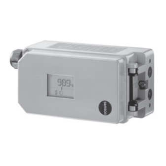
electropneumatic positioner
with profibus-pa communication
Hide thumbs
Also See for 3730-4:
- Quick start manual ,
- Mounting and operating instructions (212 pages) ,
- Configuration manual (100 pages)

Related Manuals for Samson 3730-4


Summary of Contents for Samson 3730-4
- Page 1 Series 3730 Type 3730-4 Electropneumatic Positioner with PROFIBUS-PA communication Old design New design Mounting and Operating Instructions EB 8384-4 EN (1300-1613) Firmware version 1.5x Edition August 2017 EB + CD...
- Page 2 Î For the safe and proper use of these instructions, read them carefully and keep them for later reference. Î If you have any questions about these instructions, contact SAMSON‘s After-sales Service Department (aftersalesservice@samson.de). The mounting and operating instructions for the devices are included in the scope of delivery.
-
Page 3: Table Of Contents
Contents Important safety instructions ................7 Article code ....................8 Design and principle of operation ..............9 Additional equipment ...................10 Communication ...................11 3.2.1 Configuration using the TROVIS-VIEW software ..........11 Technical data .....................12 Attachment to the control valve – Mounting parts and accessories ....18 Direct attachment ..................20 4.1.1 Type 3277-5 Actuator ..................20... - Page 4 Contents Electrical connections ...................54 5.2.1 Establishing communication ................58 Operating controls and readings ..............59 Start-up and settings ...................62 Enter fail-safe action ..................62 Adjusting the volume restriction Q ..............63 Adapting the display direction ..............63 Limiting the signal pressure ................64 Checking the operating range of the positioner ..........64 Initialization ....................65 7.6.1 MAX –...
- Page 5 Contents Code list .....................85 Dimensions in mm ..................99 15.1 Fixing levels according to VDI/VDE 3845 (September 2010) ......102 Valve characteristic selection ..............103 Index ......................130 Note: − These Mounting and Operating Instructions EB 8384-4 are valid for firmware ver- sions R 1.52 to R 1.59. The latest edition of these instructions, detailing the firm- ware version and modifications compared to the previous version, is available on our website.
- Page 6 Firmware revisions (Control R) Control R 1.43 R 1.44 to 1.46 Internal revisions R 1.52 Diagnostics All EXPERTplus diagnostic functions are available without having to acti- vate them in the positioner EB 8389 on EXPERTplus Valve Diagnos- tics). Code 48 extended The following subitems have been added to Code 48: h0: Activation/deactivation reference test h1: Reference test completed (YES/No) h3: Automatic reset of diagnosis after this time...
-
Page 7: Important Safety Instructions
Important safety instructions 1 Important safety instructions For your own safety, follow these instructions concerning the mounting, start-up, and opera- tion of the device: − The device is to be mounted, started up or operated only by trained and experienced personnel familiar with the product. -
Page 8: Article Code
Article code 2 Article code Positioner Type 3730-4 x x x 0 x 0 x x 1 x 0 0 x 0 x x With LCD and autotune, PROFIBUS-PA Explosion protection Without ATEX II 2G Ex ia IIC T6; II 2D Ex tb IIIC T80°C IP66 Ex ia IIC T6;... -
Page 9: Design And Principle Of Operation
Design and principle of operation 3 Design and principle of oper- When a system deviation occurs, the actua- tor is either vented or filled with air. If neces- ation sary, the signal pressure change can be The positioner is mounted on pneumatic con- slowed down by a volume restriction. -
Page 10: Additional Equipment
The positioner is located accessories: separately from the valve. The connection of − Direct attachment to SAMSON x and y signals to the valve is established by Type 3277 Actuators cable and piping for air (only without induc- −... -
Page 11: Communication
PROFIBUS-PA profile class B according to rameterize various SAMSON devices using DIN EN 50170 and DIN 19245-4. device-specific database modules. The 3730-4 device module can be downloaded Data are transmitted over the bus using digi- free of charge from our website (www.sam- tal, bit-synchronous Manchester coding at a son.de) at Services >... -
Page 12: Technical Data
FDT/DTM concept. Other integrations, e.g. into SIMATIC PDM using EDD Local SAMSON SSP interface and serial interface adapter Software requirements TROVIS-VIEW with device module 3730-4 9 to 32 V DC · Powered over bus line Permissible voltage supply Observe the limits in the test certificate for explosion-protected versions. - Page 13 Design and principle of operation Type 3730-4 Positioner with PROFIBUS-PA communication The technical data for the explosion-protected devices may be restricted by the limits specified in the test certificates. Direction of action Reversible Air consumption Independent of supply air approx. < 110 l to fill the actuator At Δp = 6 bar: 8.5 m...
- Page 14 Design and principle of operation Type 3730-4 Positioner with PROFIBUS-PA communication The technical data for the explosion-protected devices may be restricted by the limits specified in the test certificates. Materials Die-cast aluminum EN AC-AlSi12(Fe) (EN AC-44300) acc. to DIN EN 1706 Housing Chromated and powder paint coated · Special version: stainless steel 1.4581 External parts Stainless steel 1.4404/316L...
- Page 15 Design and principle of operation Summary of explosion protection approvals Type Certification Type of protection/comments Number A P HQ MH 104 1343 CCoE Date 2013-04-19 Ex ia IIC T6 Valid until 2018-04-18 Number STCC 0Ex ia IIC T6X; 2Ex s II T6 X Valid until 2017-10-01 Number...
- Page 16 Design and principle of operation Type Certification Type of protection/comments Number PTB 05 ATEX 2010 X II 3G Ex nA II T6 Gc; II 3D Ex tc IIIC T80°C Dc Date 2017-06-22 Number RU-C-DE. 08.B.00697 2Ex nA ic IIC T6/T5/T4 Gc X; Date 2014-12-15 Ex tc IIIC T80°C Db X, IP66...
- Page 17 Design and principle of operation EB 8384-4 EN...
-
Page 18: Attachment To The Control Valve - Mounting Parts And Accessories
The positioner is equipped with the M lever The positioner is suitable for the following (pin position 35) as standard. types of attachment: − Direct attachment to SAMSON Type 3277 Actuator − Attachment to actuators according to IEC 60534-6 (NAMUR) − Attachment according to VDI/VDE 3847 −... - Page 19 [mm] Travel [mm] lever position 25.0 120/175/240/350 35.0 355/700/750 10.0 50.0 Attachment according to IEC 60534-6 (NAMUR) SAMSON valves with Type 3271 Adjustment range at positioner Actuator Other control valves Actuator size Rated travel Min. travel Max. travel Required Assigned [cm²] [mm]...
-
Page 20: Direct Attachment
Attachment to the control valve – Mounting parts and accessories 4.1 Direct attachment Make sure that the gasket (14) points to- wards the actuator yoke. 4.1.1 Type 3277-5 Actuator 5. 15 mm travel: Keep the follower pin (2) on the M lever (1) on the back of the po- −... - Page 21 Attachment to the control valve – Mounting parts and accessories Lever Symbols Switchover plate (9) 1.1 Nut Actuator stem 1.2 Disk spring extends Follower pin Follower clamp Left attachment Right attachment Screw plug Sealing plug Actuator stem Connecting plate retracts 6.1 Seals Pressure gauge bracket Signal pressure...
-
Page 22: Type 3277 Actuator
Attachment to the control valve – Mounting parts and accessories stalled to allow any condensed water 5. Place positioner on the cover plate in that collects to drain off. such a manner that the follower pin (2) rests on the top of the follower clamp (3). 4.1.2 Type 3277 Actuator Adjust the lever (1) correspondingly and... - Page 23 Attachment to the control valve – Mounting parts and accessories Connection block Lever 1.1 Nut 12.1 Screw 1.2 Disk spring 12.2 Stopper or connection for external piping Follower pin 10 14 Switch plate Follower clamp Gasket Cover plate Formed seal Cover 11 11.1 Gasket...
-
Page 24: Attachment According To Iec 60534-6
Attachment to the control valve – Mounting parts and accessories 4.2 Attachment according to aligned with the NAMUR bracket at mid valve travel). IEC 60534-6 3. Mount connecting plate (6) or pressure − Required mounting parts and accesso- gauge bracket (7) with pressure gauges ries: Table 3 on page 50 on the positioner, making sure the two −... - Page 25 Attachment to the control valve – Mounting parts and accessories Attachment to rod-type yoke Rods with 20 to 35 mm diameter Attachment to NAMUR rib Lever Additional bracket for 1.1 Nut actuators with 1.2 Disk spring 2800 cm² and travel Follower pin ≥...
-
Page 26: Attachment According To Vdi/Vde 3847
Attachment to the control valve – Mounting parts and accessories 4.3 Attachment according to mounting screw is located in the groove of the actuator stem. VDI/VDE 3847 2. Place the adapter bracket (6) on the po- Type 3730-4xxx0xxxx0x0060xx and sitioner and mount using the screws Type 3730-4xxx0xxxx0x0070xx Positioners (6.1). - Page 27 Attachment to the control valve – Mounting parts and accessories 13.1 17.1 17.2 18 18.1 11.1 12.1 Exh. 6.2 6.1 Lever Disk spring Follower pin Follower clamp Blanking plug Adapter block Sealing plug 13.1 Screws Adapter bracket Screws Turnboard Formed seal 17.1 Formed seal 17.2...
- Page 28 Attachment to the control valve – Mounting parts and accessories 7. Insert the screws (13.1) through the mid- Place positioner on the adapter block dle holes of the adapter block (13). (13) in such a manner that the follower pin (2) rests on the top of the follower 8.
- Page 29 Attachment to the control valve – Mounting parts and accessories Attachment to NAMUR rib (see Fig. 8) on the rod and position the formed plate (15) on the opposite side. Use the nuts − Required mounting parts and accesso- and toothed lock washers to fasten the ries: Table 4 on page 50 formed plate onto the studs.
- Page 30 Attachment to the control valve – Mounting parts and accessories 6. Insert the formed seal (17.1) into the For double-acting actuators and actua- turnboard (17) and mount the turnboard tors with air purging, connect the Y2 to the adapter block (13) using the port of the adapter block to the signal screws (17.2).
- Page 31 Attachment to the control valve – Mounting parts and accessories 13.1 17.1 17.2 18.1 Exh. Lever 14.1 1.1 Nut 1.2 Disk spring Follower pin Follower plate 13.1 Screws 3.1 Follower plate 6.2 6.1 Bolt Blanking plug 14.1 Screws Sealing plug Formed plate Adapter bracket Bracket...
-
Page 32: Attachment To Type 3510 Micro-Flow Valve
M8 screws Prior to attaching the positioner to the (11.1) directly into the holes on the yoke. SAMSON Type 3278 Rotary Actuator, 5. Fasten the bracket (10) to the hex bar us- mount the associated adapter (5) to the free ing the hex screw (10.1), washer, and... - Page 33 Attachment to the control valve – Mounting parts and accessories 12.1 11.1 10.1 Lever 1.1 Nut 1.2 Disk spring Follower pin NOTICE Follower plate Only use the connecting plate (6) Connecting plate included in the accessories to connect 6.1 Seals supply and output! Pressure gauge bracket Never screw threaded parts directly...
-
Page 34: Heavy-Duty Version
Attachment to the control valve – Mounting parts and accessories 2. Place coupling wheel (4) with flat side side of the positioner housing (see section facing the actuator on the follower clamp 4.6). (3). Refer to Fig. 11 to align slot so that it 6. - Page 35 Attachment to the control valve – Mounting parts and accessories (7, 8) 10.1 NOTICE 80 mm Only use the connecting plate (6) included in the accessories to connect 130 mm supply and output! Never screw threaded parts directly into housing! Slot Legend for Fig. 10 and Fig. 11...
-
Page 36: Reversing Amplifier For Double-Acting Actuators
Attachment to the control valve – Mounting parts and accessories 2. For SAMSON Type 3278 and VETEC the follower pin (Ø5 mm) included in the S160 Rotary Actuators, screw the adapt- mounting kit to pin position 90°. er (5) onto the free end of the shaft or 6. - Page 37 Adhesive label Actuator shaft or adapter Adapter 10.1 10.1 Attachment according to VDI/VDE 3845 SAMSON Type 3278 (Sept. 2010) fixing level 1, AA1 to AA4 VETEC S160, VETEC R size, see section 15.1 Fig. 13: Attachment to rotary actuators (heavy-duty version) EB 8384-4 EN...
-
Page 38: Reversing Amplifier (1079-1118 Or 1079-1119)
Attachment to the control valve – Mounting parts and accessories The following applies to all reversing am- 2. Thread the special nuts (1.3) from the ac- plifiers: cessories of the reversing amplifier into the boreholes of the connecting plate. The signal pressure of the positioner is sup- plied at the output 1 of the reversing amplifi- 3. - Page 39 Attachment to the control valve – Mounting parts and accessories From the positioner Output 38 Supply 9 Control signals to the actuator Reversing amplifier Connecting plate 1.1 Special screws 6.1 O-rings 1.2 Gasket 6.2 Screws 1.3 Special nuts 1.4 Rubber seal 1.5 Sealing plug 1.6 Filter Fig. 14: Mounting a reversing amplifier (1079-1118 or 1079-1119)
-
Page 40: Attachment Of External Position Sensor
Attachment to the control valve – Mounting parts and accessories 4.7 Attachment of external po- Note sition sensor − In addition, the instructions in sections 5.1 and 5.2 apply for the pneumatic and elec- trical connection. Operation and setting are described in sections 7 and 8. -
Page 41: Mounting The Position Sensor With Direct Attachment
Attachment to the control valve – Mounting parts and accessories 4.7.1 Mounting the position − Turn the connecting plate (9) so that the correct symbol for the fail-safe action sensor with direct at- "actuator stem extends" or "actuator stem tachment retracts"... - Page 42 Attachment to the control valve – Mounting parts and accessories Type 3277 Actuator with 175 to 750 cm²: 6. Place the mounting plate together with the sensor onto the actuator yoke so that The signal pressure is routed to the connec- the follower pin (2) rests on the top of the tion at the side of the actuator yoke for the follower clamp (3).
-
Page 43: Mounting The Position Sensor With Attachment According To Iec 60534-6
Attachment to the control valve – Mounting parts and accessories 4.7.2 Mounting the position 120 to 350 cm² actuators with 15 mm rated travel. For other actuator sizes or travels, se- sensor with attachment lect the lever and pin position from the travel according to table on page 19. -
Page 44: Mounting The Position Sensor To Type 3510 Micro-Flow Valve
Attachment to the control valve – Mounting parts and accessories 4.7.3 Mounting the position hole for pin position 17. Place the lever (1) and disk spring (1.2) on the sensor sensor to Type 3510 Mi- shaft. Place the lever in mid-position and cro-flow Valve hold it in place. -
Page 45: Mounting On Rotary Actuators
Attachment to the control valve – Mounting parts and accessories 4.7.4 Mounting on rotary ac- 4. Place the lever (1) and disk spring (1.2) on the sensor shaft. Place the lever in tuators mid-position and hold it in place. Screw −... -
Page 46: Mounting The Leakage Sensor
Attachment to the control valve – Mounting parts and accessories 4.8 Mounting the leakage The M8 threaded connection on the NAMUR rib should preferably be used to mount the sensor sensor (Fig. 19). Fig. 19 Normally, the control valve is delivered with If the positioner was mounted directly onto positioner and leakage sensor already the actuator (integral attachment), the... -
Page 47: Attaching Positioners With Stainless Steel Housings
Attachment to the control valve – Mounting parts and accessories 4.9 Attaching positioners with Attachment to rotary actuators stainless steel housings All mounting kits from Table 5 can be used except for the heavy-duty version. Connect- Positioners with stainless steel housings re- ing plate in stainless steel. -
Page 48: Required Mounting Parts And Accessories
Attachment to the control valve – Mounting parts and accessories Attachment according to IEC 60534-6 Should other valve accessories be used (NAMUR rib or attachment to rod-type which vent the actuator (e.g. solenoid valve, yokes) and to rotary actuators volume booster, quick exhaust valve), this ex- haust air must also be included in the purg- The positioner requires an additional port for ing function. - Page 49 Attachment to the control valve – Mounting parts and accessories Table 2: Direct attachment to Type 3277 Actuator (Fig. 4) Order no. Standard version for actuators 175, 240, 350, 355, 700, 750 cm² 1400-7453 Mounting parts Version compatible with paint for actuators 175, 240, 350, 355, 700, 750 cm² 1402-0941 G ...
- Page 50 Table 4: Attachment according to VDI/VDE 3847 (Fig. 6 and Fig. 8) Electropneumatic positioners with VDI/VDE 3847 interface (Type 3730-4xxx0xxxx0x0070xx) Order no. Interface adapter 1402-0257 Mounting kit for attachment to SAMSON Type 3277 Actuator with 175 to 750 cm² 1402-0868 Mounting kit for attachment to SAMSON Type 3271 Actuator or non-SAMSON 1402-0869 actuators ISO 228/1-G¼...
- Page 51 1400-9837 Attachment to SAMSON Type 3278 with 160/320 cm², CrNiMo steel bracket 1400-7614 Attachment to SAMSON Type 3278 with 160 cm² and to VETEC Type S160, Type R and 1400-9245 Type M, heavy-duty version 1400-5891 Attachment to SAMSON Type 3278 with 320 cm² and to VETEC Type S320, heavy-duty...
- Page 52 Table 6: General accessories Order no. Serial interface adapter (SAMSON SSP interface to RS-232 port on a computer) 1400-7700 Isolated USB interface adapter (SAMSON SSP interface to USB port on a computer) 1400-9740 including TROVIS-VIEW CD-ROM Table 7: Attachment of external position sensor Order no.
-
Page 53: Connections
Connections 5 Connections ary cable glands for metal or copper tubing or plastic hoses can be used. WARNING NOTICE Risk of injury due to the actuator stem ex- tending or retracting. Risk of malfunction due to failure to comply Do not touch or block the actuator stem. with required air quality. -
Page 54: Signal Pressure (Output)
Connections 5.2 Electrical connections The bench range is written on the nameplate either as the spring range or signal pressure range depending on the actuator. The direc- DANGER tion of action is marked FA or FE, or by a Risk of fatal injury due to the formation of symbol. - Page 55 Connections smaller than 0.1 mm. Protect the conductor The maximum permissible values specified ends against splicing, e.g. by using wire-end in the statement of conformity and its ad- ferrules. When two separate cables or wires denda apply when interconnecting the equipment with energy-limited circuits in are used for connection, an additional cable type of protection Ex nL IIC.
- Page 56 Connections Observe the relevant regulations for instal- Refer to the PROFIBUS-PA User and Installa- lation in hazardous areas. tion Guide (PNO document 2.092) for more information. Accessories Limit switch The operation of the limit switch requires a Cable glands M20 x 1.5 Order no. switching amplifier to be connected in the Black plastic (6 to 12 mm clamping range) 8808-1011...
- Page 57 Connections PROFIBUS-DP(E) RS 485 Controller/PLC/control system PROFIBUS-DP(E) RS 485 Display and operating PROFIBUS-DP(E) RS 485 elements PROFIBUS-DP(E) RS 485 Segment coupler PROFIBUS-PA IEC 61158-2 PROFIBUS-PA IEC 61158-2 Bus termination 3730-40 3730-40 3730-40 3730-40 3730-40 3730-40 3730-40 3730-40 Controller/PLC/control system PROFIBUS-DP RS 485 Display and operating PROFIBUS-DP RS 485 elements...
-
Page 58: Establishing Communication
Connections 5.2.1 Establishing communica- tion The communication structure between the controller, logic solvers (PLC) or automation system, or between a computer or work sta- tion and the positioner(s) is implemented us- ing a segment coupler (see Fig. 21) accord- ing to the PROFIBUS guidelines. Explosion-protected versions of PROFIBUS-PA segment couplers must be used in hazardous areas. -
Page 59: Operating Controls And Readings
Operating controls and readings 6 Operating controls and AIR TO OPEN always applies to positioners with a mounted reversing amplifier for dou- readings ble-acting rotary actuators (connections ac- Rotary pushbutton cording to section 4.6). The rotary pushbutton is located underneath Volume restriction Q the front protective cover. - Page 60 Operating controls and readings Readings been exceeded. Lever and pin position must be checked. Icons assigned to certain codes, parameters and functions are indicated on the display. Status messages Operating modes: Maintenance alarm − Maintenance demanded/ − Manual mode (see section 8.2.1) −...
- Page 61 Operating controls and readings Manual mode Closed-loop operation Code Malfunction/fault Bar graph for set point Designation deviation or lever position Position Parameters Units Binary contact 1 Binary contact 2 Configuration Fail-safe position active Maintenance demanded enabled Maintenance required AUtO Automatic Clockwise Counterclockwise blinking: positioner not initialized...
-
Page 62: Start-Up And Settings
Start-up and settings 7 Start-up and settings Code 0 is displayed when a positioner has been initialized. The positioner is in the last active operating mode. NOTICE Risk of malfunction due to incorrect sequence WARNING of mounting, installation, and start-up. Risk of injury due to the actuator stem ex- Keep the following sequence. -
Page 63: Adjusting The Volume Restriction Q
0 % when the valve is closed at the actuator in SAMSON actuators: and 100 % when the valve is open. If this is − The SIDE position applies for actuators... -
Page 64: Limiting The Signal Pressure
Start-up and settings Turn g Code 3, display: No Press , Code 3 blinks. Reading direction for right attachment of pneumatic Turn YES connections Press , display: Limit the signal pressure: Reading direction for left attachment of pneumatic connections Pressure limit Default: No If the displayed data appear upside down,... -
Page 65: Initialization
Start-up and settings Press . The positioner changes to the man- WARNING ual mode ( ). Risk of injury due to the actuator stem ex- Check the operating range: tending or retracting. Before exchanging the lever or changing the pin position, disconnect the supply air and Manual set point w electrical auxiliary power. - Page 66 Start-up and settings − Maximum range (MAX) (standard range) Initialization mode for simple start-up of Initialization successfully com- valves with two clearly defined mechani- pleted. Positioner in automatic mode ( ) cal end positions, e.g. three-way valves (see section 7.6.1) − Nominal range (NOM) The time required for the initialization proce- Initialization mode for all globe valves dure depends on the actuator transit time and...
-
Page 67: Max - Initialization Based On Maximum Range
Start-up and settings Enable configuration: Set point Direction of Valve Closed position action CLOSED Note OPEN at If no settings are entered within 120 sec- Actuator stem onds, the enabled configuration function be- extends (FA) 0 % 100 % comes invalid. AIR TO OPEN Actuator stem retracts (FE) -
Page 68: Nom - Initialization Based On Nominal Range
Start-up and settings travel/angle range end (Code 9) can also this is not the case, initialization is automati- only be displayed and modified in %. cally canceled (error message Code 52) be- cause the nominal travel could not be For a reading in mm/°, enter the pin posi- achieved. -
Page 69: Man - Initialization Based On A Manually Selected Range
Start-up and settings The positioner calculates the differential trav- Turn Pin position on lever (see relevant el/angle from the OPEN and CLOSED posi- section on attachment) tions and adopts it as the operating range Press with limits of lower travel/angle range value Turn ... -
Page 70: Sub - Substitute Calibration
Start-up and settings 7.6.4 SUb – Substitute calibra- Select the initialization mode: tion Init mode A complete initialization procedure takes Default MAX several minutes and requires the valve to move through its entire travel range several times. In the SUb initialization mode, the Turn ... - Page 71 Start-up and settings Select the initialization mode: Enable configuration Default: No Init mode Default MAX Turn g Code 3, display: No Press , Code 3 blinks. Turn Code 6 Turn YES Press Press , display: Turn SUb Press to confirm the SUb as the initializa- Enter the pin position and nominal range:...
- Page 72 Start-up and settings Change pressure limit and control parame- Enter closing direction and blocking position: ters: Closing direction (direction of rotation causing the valve to Note move to the CLOSED position (view onto positioner display) Do not change the pressure limit (Code 16). Default: CCL (counterclockwise) Only change the control parameters K (Code 17) and T...
-
Page 73: Zero Calibration
Start-up and settings Zero point calibration Note Finally, if process operations allow it, the ze- Since initialization has not been completed, ro point must be calibrated according to sec- the error code 76 (no emergency mode) and tion 7.7. possibly also error code 57 (control loop) may appear on the display. -
Page 74: Reset To Default Settings
(see code list in section 14). TROVIS-VIEW operator interface connected over the serial interface in the positioner. Use Enable configuration: the TROVIS-VIEW software with 3730-4 de- Turn g Code 3, display: No vice module installed. Press , Code 3 blinks. - Page 75 Start-up and settings Default 126 Enable configuration: Turn g Code 3, display: No Press , Code 3 blinks. Turn YES Press , display: Setting the bus address: Turn Code 46 Press , Code 46 blinks. Turn Required bus address Press 10 seconds ...
-
Page 76: Operation
Operation 8 Operation Turn to select the required code. Press to activate the selected code. The code number starts to blink. WARNING Risk of injury due to the actuator stem ex- Turn to select the setting. tending or retracting. Press to confirm the selected setting. -
Page 77: Fail-Safe Position (Safe)
Operation Note The positioner automatically returns to Automatic mode Code 0 if no settings are made within 120 seconds, but remains in the manual mode. Switching to manual mode (MAN) Switch to automatic mode Turn Code 0 Press , Code 0 blinks. Turn ... -
Page 78: Fault/Malfunction
Operation Exit the fail-safe position − Maintenance required The positioner still performs its control Turn Code 0 task (with restrictions). A maintenance Press , Code 0 blinks. demand or above average wear has Turn and select the required operating been determined. -
Page 79: Confirming Error Messages
Operation 8.3.1 Confirming error mes- The condensed state is displayed represented by the following icons: sages Condensed state Positioner display Enable configuration: Maintenance alarm Text e.g. tESting, Note Function check TunE or tESt If no settings are entered within 120 sec- Maintenance required/ onds, the enabled configuration function be- maintenance demanded... -
Page 80: Adjusting The Limit Switch
Adjusting the limit switch 9 Adjusting the limit switch When the tag (1) is located in the inductive field of the switch, the switch assumes a high The positioner version with an inductive limit resistance. When it moves outside the field, switch has an adjustable tag (1) mounted on the switch assumes a low resistance. -
Page 81: Retrofitting An Inductive Limit Switch
Adjusting the limit switch The required switching function, i.e. whether For OPEN position: the output relay is to be picked up or re- Initialize the positioner. leased when the tag enters the field, must be Move the valve to 95 % in the MAN selected at the switching amplifier, if re- mode (see display). - Page 82 Adjusting the limit switch 1. Take off the rotary pushbutton (3) and cap (1), unthread the five fastening screws (2) and lift off the plastic cover (9) together with the display, taking care not to dam- age the ribbon cable (between PCB and display).
-
Page 83: Maintenance
11 Servicing explosion-protected When updates are performed by a service employee appointed by SAMSON, the up- devices date is confirmed on the device by the test If a part of the device on which the explosion mark assigned by SAMSON’s Quality Assur-... -
Page 84: Maintenance, Calibration And Work On Equipment
Maintenance, calibration and work on equipment Updates on site: Updates on site are only permitted after the plant operator presented a signed hot work permit. After updating has been completed, add the current firmware to the nameplate; this can be done using labels. 13 Maintenance, calibration and work on equipment Interconnection with intrinsically safe cir-... -
Page 85: Code List
Code list 14 Code list Code Parameter – Readings/ Description values [default setting] Note: Codes with marked with an asterisk (*) must be enabled with Code 3 prior to configuration. Operating mode Switchover from automatic to manual mode is bumpless. In fail-safe position, the S icon is displayed. [MAN] Manual mode In MAN and AUtO mode, the system deviation is represented by the AUtO Automatic mode... - Page 86 Code list Code Parameter – Readings/ Description values [default setting] Nominal range Nominal valve travel or opening angle must be entered for nominal (NOM) or substitute (SUb) initialization. mm or angle °, ESC The possible adjustment range depends on the pin position from the table for Code 4.
- Page 87 Code list Code Parameter – Readings/ Description values [default setting] Travel/angle range end Upper range value for travel/angle in nominal or operating range (upper x-range value) The value is displayed or must be entered. 20.0 to [100.0 %] of the The characteristic is adapted. nominal range, ESC Example: The operating range is modified, for example, to limit the Note: Specified in mm or...
- Page 88 Code list Code Parameter – Readings/ Description values [default setting] 15* Reference variable range If the set point w reaches up to the entered percentage at the final end (w-end) value that causes the valve to open, the actuator is immediately filled with air (with AIR TO OPEN) or completely vented (with AIR TO 50.0 to 100.0 % of the CLOSE).
- Page 89 Linear [0] to 9, ESC Equal percentage Reverse equal percentage SAMSON butterfly valve, linear SAMSON butterfly valve, equal percentage VETEC rotary plug valve, linear VETEC rotary plug valve, equal percentage Segmented ball valve, linear Segmented ball valve, equal percentage User-defined (defined over operator software) Note The various characteristics are listed in the Appendix (section 16).
- Page 90 Code list Code Parameter – Readings/ Description values [default setting] 24* LV total valve travel Limit value of total valve travel. If the limit is exceeded, the error mes- sage and the icon corresponding to the condensed state appear. 1000 to 99 · 10 [1.000000], ESC Exponential reading from 9999 travel cycles on-...
- Page 91 Code list Code Parameter – Readings/ Description values [default setting] 43 Firmware info control Read only Indicates the positioner type and current firmware version in alter- nating sequence. 44 y info Read only [0] to 100 %, 0P, MAX, – – Indicates the control signal y in % in relation to the travel range de- –...
- Page 92 Code list Initialization errors Error codes – Condensed state message active, when prompted, Err appears. Recommended action When fault alarms exist, they are displayed here. 50 x > permissible Value of measuring signal too high or too low; the lever operates near its range mechanical stops.
- Page 93 Code list Error codes – Condensed state message active, when prompted, Err appears. Recommended action When fault alarms exist, they are displayed here. 53 Initialization time Initialization takes too long. The positioner returns to the previous operating exceeded mode. (Init time >) •...
- Page 94 Code list Operational errors Error codes – Condensed state message active, when prompted, Err appears. Recommended action When fault alarms exist, they are displayed here. 57 Control loop Control loop error, the valve no longer follows the controlled variable within tolerable times (tolerance band alarm Code 19).
- Page 95 Return positioner to SAMSON AG for repair. action 64 i/p converter (y) Current circuit of i/p converter interrupted. Status classification Maintenance alarm (cannot be classified) Recommended Cannot be remedied. Return positioner to SAMSON AG for repair. action EB 8384-4 EN...
- Page 96 Check calculation Hardware controller monitored by test calculation. Status classification Maintenance alarm (cannot be classified) Recommended action Confirm error. If this is not possible, return positioner to SAMSON AG for repair. Data errors Error codes – Recommended Condensed state message active, when prompted, Err appears.
- Page 97 Error in data from production calibration. The positioner continues oper- ation with cold start values. Status classification [Maintenance required] Recommended action Return positioner to SAMSON AG for repair. General parameters Error in parameters not critical to control operation. Status classification [Maintenance required] Recommended action Confirm error.
- Page 98 Status classification Maintenance alarm (cannot be classified) Interrupt fieldbus signal and restart the positioner. Recommended action If not successful, return positioner to SAMSON AG for repair. Error in option parameters. Option parameters Status classification [Maintenance required] Recommended action Return positioner to SAMSON AG for repair.
-
Page 99: Dimensions In Mm
Dimensions in mm 15 Dimensions in mm Pressure Attachment according to IEC 60534-6 gauge or connecting plate External position bracket sensor Lever (see Fig. 30) Direct attachment M20x1.5 Output (38) Supply (9) Fig. 27: NAMUR and direct attachment EB 8384-4 EN... - Page 100 Dimensions in mm Attachment according to VDI/VDE 3847 to Type 3277 Lever (see Fig. 30) Attachment according to VDI/VDE 3847 to a NAMUR Fig. 28: Attachment according to VDI/VDE 3847 EB 8384-4 EN...
- Page 101 Dimensions in mm Heavy-duty version Output Y Output Y Supply (9) Reversing Output Y Output Y amplifier (optional)* Ø 101 Light version Output A1 Supply (9) Reversing amplifier Output A2 (optional)* Connecting plate G ¼ or ¼ NPT * Reversing amplifier Type 3710 (see drawing of heavy-duty version for dimensions) −...
-
Page 102: Fixing Levels According To Vdi/Vde 3845 (September 2010)
Dimensions in mm Lever 10...17 17 mm 25 mm 33 mm 25 mm 50 mm 66 mm 70 mm 100 mm 116 mm 100 mm 200 mm 216 mm Fig. 30: Lever 15.1 Fixing levels according to VDI/VDE 3845 (September 2010) Fixing level 2 (bracket surface) Fixing level 1 (actuator surface) Actuator Dimensions in mm Size Ød 5.5 for M5... -
Page 103: Valve Characteristic Selection
Valve characteristic selection 16 Valve characteristic selection The characteristics that can be selected in Code 20 are shown in the following in graph form. Note A characteristic can only be defined (user-defined characteristic) using a workstation/operat- ing software (e.g. TROVIS-VIEW). Linear (select characteristic: 0) Travel/ angle of rotation [%] Reference variable [%]... - Page 104 SAMSON butterfly valve linear (select SAMSON butterfly valve equal percentage characteristic: 3) (select characteristic: 4) Travel/ angle of rotation [%] Travel/ angle of rotation [%] Reference variable [%] Reference variable [%] VETEC rotary plug valve linear (select VETEC rotary plug valve equal percentage...
- Page 105 EB 8384-4 EN...
- Page 106 EB 8384-4 EN...
- Page 107 EB 8384-4 EN...
- Page 108 EB 8384-4 EN...
- Page 109 EB 8384-4 EN...
- Page 110 EB 8384-4 EN...
- Page 111 EB 8384-4 EN...
- Page 112 EB 8384-4 EN...
- Page 113 EB 8384-4 EN...
- Page 114 EB 8384-4 EN...
- Page 115 EB 8384-4 EN...
- Page 116 EB 8384-4 EN...
- Page 117 EB 8384-4 EN...
- Page 118 EB 8384-4 EN...
- Page 119 EB 8384-4 EN...
- Page 120 Elektropneumatischer Stellungsregler mit PROFIBUS-PA-Kommunikation / Electropneumatic Positioner with PROFIBUS-PA communication / Positionneur électropneumatique avec communication PROFIBUS-PA Typ/Type/Type 3730-4... wird die Konformität mit den einschlägigen Harmonisierungsrechtsvorschriften der Union bestätigt / the conformity with the relevant Union harmonisation legislation is declared with/ est conforme à...
- Page 121 Explosion Protection 94/9/EC (bis/to 2016-04-19) EN 60079-15:2010, EN 60079-31:2009 Explosion Protection 2014/34/EU (ab/from 2016-04-20) Hersteller / Manufacturer / Fabricant: SAMSON AKTIENGESELLSCHAFT Weismüllerstraße 3 D-60314 Frankfurt am Main / Germany Frankfurt / Francfort, 2016-04-06 Im Namen des Herstellers/ On behalf of the Manufacturer/ Au nom du fabricant.
- Page 122 Explosion Protection 94/9/EC (bis/to 2016-04-19) EN 60079-15:2010, EN 60079-31:2009 Explosion Protection 2014/34/EU (ab/from 2016-04-20) Hersteller / Manufacturer / Fabricant: SAMSON AKTIENGESELLSCHAFT Weismüllerstraße 3 D-60314 Frankfurt am Main / Germany Frankfurt / Francfort, 2016-04-06 Im Namen des Herstellers/ On behalf of the Manufacturer/ Au nom du fabricant.
- Page 123 EB 8384-4 EN...
- Page 124 EB 8384-4 EN...
- Page 125 EB 8384-4 EN...
-
Page 126: Index
Index Index Configuration At the positioner ......76 With TROVIS-VIEW ......11 Accessories ........48–50 Connections Additional equipment Electric ........... 54 External position sensor ....10 Pneumatic ........53 Limit switch ........10 Controlled variable ......... 9 Solenoid valve ........ 10 Air purging of the actuator’s spring Default Values ........ - Page 127 Index Reference variable (set point)....9 Initialization Reset ........... 74 Manually selected range (MAN) 66, 69 Reversing amplifier ....... 36 Maximum range (MAX) ..... 66, 67 Rotary pushbutton ........ 59 Nominal range (NOM) ..... 66, 68 Substitute calibration (SUb) ..66, 70 Select characteristic ....
- Page 128 SAMSON AG · MESS- UND REGELTECHNIK Weismüllerstraße 3 · 60314 Frankfurt am Main, Germany Phone: +49 69 4009-0 · Fax: +49 69 4009-1507 EB 8384-4 EN samson@samson.de · www.samson.de...
Need help?
Do you have a question about the 3730-4 and is the answer not in the manual?
Questions and answers