
Related Manuals for Tektronix TLA7S08 Series


Summary of Contents for Tektronix TLA7S08 Series
- Page 1 TLA7S08 & TLA7S16 Serial Analyzer Modules PCI Express Instruction Manual *P077014901* 077-0149-01...
- Page 3 This document applies to TLA System Software 5.6 or higher. Warning These servicing instructions are for use by qualified personnel only. To avoid personal injury, do not perform any servicing unless you are qualified to do so. Refer to all safety summaries prior to performing service. www.tektronix.com 077-0149-01...
- Page 4 Copyright © Tektronix. All rights reserved. Licensed software products are owned by Tektronix or its subsidiaries or suppliers, and are protected by national copyright laws and international treaty provisions. Tektronix products are covered by U.S. and foreign patents, issued and pending. Information in this publication supersedes that in all previously published material.
- Page 5 Tektronix, with shipping charges prepaid. Tektronix shall pay for the return of the product to Customer if the shipment is to a location within the country in which the Tektronix service center is located. Customer shall be responsible for paying all shipping charges, duties, taxes, and any other charges for products returned to any other locations.
- Page 6 In order to obtain service under this warranty, Customer must notify Tektronix of the defect before the expiration of the warranty period. If Tektronix is unable to provide a replacement that is free from defects in materials and workmanship within a reasonable time thereafter, Customer may terminate the license for this software product and return this software product and any associated materials for credit or refund.
-
Page 7: Table Of Contents
Table of Contents General Safety Summary ..................Service Safety Summary..................Environmental Considerations .................. Preface ......................Related Documentation ..................List of Terms ....................Introduction ......................Product Description.................... Serial Analyzer Compatibility................Installing the Serial Analyzer Module............... List of Compatible Probes ..................Connecting the Serial Analyzer to the System Under Test (SUT)........Applying and Removing Power ................ - Page 8 Table of Contents List of Figures Figure 1: TLA7S16 Module and P6716 midbus probe............Figure 2: TLA7S16 Serial analyzer front panel..............Figure 3: TLA7S16 Serial analyzer rear panel ..............Figure 4: Installing a serial analyzer module ..............Figure 5: Connecting a mid-bus probe to your SUT ............Figure 6: Connecting a slot interposer probe ..............
- Page 9 Table of Contents List of Tables Table i: Terms used in this document ................Table 1: Front panel indicators and connectors ..............Table 2: Serial analyzer probes ................... Table 3: Status indicators in the Setup window ..............Table 4: Trigger events ................... Table 5: Trigger event recognizer resources..............
-
Page 10: General Safety Summary
General Safety Summary General Safety Summary Review the following safety precautions to avoid injury and prevent damage to this product or any products connected to it. To avoid potential hazards, use this product only as specified. Only qualified personnel should perform service procedures. While using this product, you may need to access other parts of a larger system. - Page 11 General Safety Summary Terms in this Manual These terms may appear in this manual: WARNING. Warning statements identify conditions or practices that could result in injury or loss of life. CAUTION. Caution statements identify conditions or practices that could result in damage to this product or other property.
-
Page 12: Service Safety Summary
Service Safety Summary Service Safety Summary Only qualified personnel should perform service procedures. Read this Service Safety Summary and the General Safety Summary before performing any service procedures. Do Not Service Alone. Do not perform internal service or adjustments of this product unless another person capable of rendering first aid and resuscitation is present. -
Page 13: Environmental Considerations
Directive 2002/96/EC on waste electrical and electronic equipment (WEEE). For information about recycling options, check the Support/Service section of the Tektronix Web site (www.tektronix.com). Restriction of Hazardous This product has been classified as Monitoring and Control equipment, and is outside the scope of the 2002/95/EC RoHS Directive. - Page 14 Environmental Considerations viii TLA7S08 &TLA7S16 Serial Analyzer Modules Instruction Manual...
-
Page 15: Preface
Preface Preface This manual contains information needed to install and use a Tektronix serial analyzer module to debug, validate, and verify computer and embedded systems. Related Documentation The following table lists related documentation for your serial analyzer. The documentation is available on the TLA Documentation CD and on the Tektronix Web site (www.tektronix.com/manuals). -
Page 16: List Of Terms
Preface List of Terms The following table lists terms that appear in this manual. For a more extensive list of PCI Express-specific terms, refer to the latest PCI Express Base Specification document. Table i: Terms used in this document Term Description Link A connection between two PCI Express devices. -
Page 17: Introduction
The TLA7S08 & TLA7S16 Serial Analyzer modules are tools used to acquire and analyze data traveling on a PCI Express (PCIe) Gen1 or Gen2 serial bus. The serial analyzer modules can be installed in either a Tektronix portable or benchtop logic analyzer mainframe. Specially designed probes connect from the module to a circuit board in your system under test (SUT), or to a PCI Express card device. -
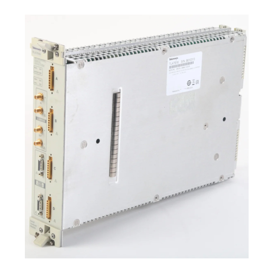
Page 18: Figure 2: Tla7S16 Serial Analyzer Front Panel
Introduction Front Panel The front panel provides indicators for checking the basic status of the serial analyzer, four probe connectors, two probe power connectors, and four connectors for a reference clock. (See Figure 3 on page 4.) A description of the indicators and connectors is provided. -
Page 19: Table 1: Front Panel Indicators And Connectors
Introduction Table 1: Front panel indicators and connectors Item number Indicator or connector Description READY indicator The READY indicator lights continuously after the serial analyzer module successfully completes the power-on process. If the indicator fails to light within five seconds of power-on, an internal module failure may be present. -
Page 20: Figure 3: Tla7S16 Serial Analyzer Rear Panel
Introduction Figure 3: TLA7S16 Serial analyzer rear panel TLA7S08 &TLA7S16 Serial Analyzer Modules Instruction Manual... -
Page 21: Serial Analyzer Compatibility
Always power off the instrument before installing or removing modules Cover any empty module slots with a blank cover (Tektronix part number, 333-4206-xx). Install the modules in the mainframe. (See Figure 4.) Use a screwdriver to tighten the retaining screws to 2.5 in-lbs after seating the modules in place. -
Page 22: Figure 4: Installing A Serial Analyzer Module
Introduction Figure 4: Installing a serial analyzer module TLA7S08 &TLA7S16 Serial Analyzer Modules Instruction Manual... -
Page 23: List Of Compatible Probes
Introduction List of Compatible Probes The following probes are compatible with the serial analyzer module: Table 2: Serial analyzer probes Probe Description P6708 8-Channel PCI Express Mid-bus probe P6716 16-Channel PCI Express Mid-bus probe P6701S 2-Channel PCI Express x1 Slot Interposer probe P6704S 8-Channel PCI Express x4 Slot Interposer probe P6708S... -
Page 24: Figure 5: Connecting A Mid-Bus Probe To Your Sut
Introduction 2. Align the probe head with the retention mechanism. Both are keyed so that the probe can only be inserted one way. 3. Press the probe head into the retention mechanism. Figure 5: Connecting a mid-bus probe to your SUT 4. -
Page 25: Figure 6: Connecting A Slot Interposer Probe
NOTE. Although you do not need to power off the TLA before connecting the slot probe to the SUT, Tektronix recommends that you DO NOT connect the probe power to the TLA until after making all other connections. 1. Disconnect the power supply to your SUT. Unplug the PC power supply if your SUT is connected to one. -
Page 26: Figure 7: Connecting A 16-Channel Probe To The Tla7S16 Serial Analyzer Module
Introduction Figure 7: Connecting a 16-channel probe to the TLA7S16 serial analyzer module a. Plug the probe connector labeled 0, 2, 4, and 6 (channels) into the top connector on the module (A). b. Plug the probe connector labeled 1, 3, 5, and 7 (channels) into the second connector (B). -
Page 27: Applying And Removing Power
Introduction Connecting a Clock Cable Two clock connection cables are included with your serial analyzer module. One is for connecting the reference clock input of the module to the SUT or slot interposer probe, and the other is a jumper cable for connecting one module to another. - Page 28 Introduction TLA7S08 &TLA7S16 Serial Analyzer Modules Instruction Manual...
-
Page 29: Setting Up The Serial Analyzer
Setting Up the Serial Analyzer Before you use the serial analyzer, you need to verify that your mainframe has the most current TLA Application software and TLA PCI Express Support software. The software must be installed on all mainframes and PCs that will use the serial analyzer modules, including any PCs that will remotely control the serial analyzer. -
Page 30: Updating The Serial Analyzer Module Firmware
TLA PCI Express Support software. 1. If you haven’t already done so, exit the TLA application. 2. Click Start → All Programs → Tektronix Logic Analyzer → TLA Firmware Loader. 3. Select your mainframe instrument from the TLA Connection dialog box. -
Page 31: Open The Setup Window
Setting Up the Serial Analyzer Open the Setup Window NOTE. There is a separate Setup window for each installed module. Make sure to select the Setup window that applies to the correct module. Open the serial analyzer Setup window by doing one of the following: Click the serial analyzer Setup Icon in the TLA Explorer. -
Page 32: Monitoring Signal Activity
Setting Up the Serial Analyzer Monitoring Signal Activity After you have connected the probes and installed the software and firmware, monitor signal activity on each of the channels to make sure that your system is operating correctly and that the probes are connected properly. A graphic representation of the serial analyzer module shows a status indicator for each channel. - Page 33 Recognize the clock signal by directly connecting to the SUT with a clock cable. Tektronix recommends connecting a clock cable to assure that data is accurately synchronized with the clock signal. Set the SUT Reference Clock selection to Connected at Front Panel and then select an approximate frequency (100 ±10% or 125 MHz ±10%).
- Page 34 Setting Up the Serial Analyzer Storage Settings Specify the amount of data to store (symbols per channel), and set the trigger position relative to the amount of data stored. A trigger position setting of 0% indicates that data will be stored after the trigger event occurs. A trigger position setting of 100% indicates that data storage will stop when the trigger event occurs.
-
Page 35: Figure 10: Assigning Channels To Lanes
Setting Up the Serial Analyzer Figure 10: Assigning channels to lanes TLA7S08 &TLA7S16 Serial Analyzer Modules Instruction Manual... -
Page 36: Training
Setting Up the Serial Analyzer Perform the following steps to assign input channels to lanes: 1. Determine the correlation between each lane and each input channel. 2. Select the left edge of the input channel indicator. The left edge becomes highlighted to show that it has been selected. 3. -
Page 37: Figure 11: Default Detector And Listener Channels On The Probe Connector
Figure 11: Default detector and listener channels on the probe connector Figure 12: L0s Detector settings You should not need to change any settings for most configurations. Tektronix recommends that you use the standard (default) settings. If necessary, manually change the settings. Some link configurations will require that you change the... - Page 38 Be aware when this situation occurs and follow the suggested link formats that are provided in the P67xx Series Probes Instruction Manual. Contact your local Tektronix representative for assistance. To temporarily bypass the detectors to observe data on all lanes at a slower transition detection rate, turn off the L0s detection.
- Page 39 FIFOs on the down-side link must be reset.) To avoid problems when using bidirectional links with buses entering or exiting electrical idle states, Tektronix recommends that you disable the Timestamp Averaging feature (right-click the mouse in the Setup window to display the context menu and clear the Timestamp Averaging selection).
-
Page 40: Defining A Trigger
Setting Up the Serial Analyzer Defining a Trigger After defining parameters in the Setup window, you need to define a trigger that tells the serial analyzer when to begin recording data. You define a trigger in the Trigger window. Open the Trigger Window Open the Trigger window by doing one of the following: Click the Serial Analyzer Trigger icon in the TLA Explorer. -
Page 41: Table 4: Trigger Events
Setting Up the Serial Analyzer Adding States, Clauses, A trigger definition is a logical expression consisting of events and actions within clauses, within states. The default Trigger window starts with one state (State Events, and Actions 1). and one clause (Clause 1). A trigger definition can have up to eight trigger states with eight trigger clauses per state. -
Page 42: Figure 14: Specifying A Tlp Event
Setting Up the Serial Analyzer Table 5: Trigger event recognizer resources Event recognizer Description DLLP packet recognizers 8 separate DLLP recognizers. The total number of unique DLLPs that can be detected depend on the link width and direction. x1, x2, or x4 links 8 unique DLLP packet recognizer resources 4 unique DLLP packet recognizer resources x8 and x16 links... -
Page 43: Figure 16: Specifying A Dllp Event
Setting Up the Serial Analyzer NOTE. The X and $ characters appear whenever you define a TLP, DLLP, or a symbol sequence Event. An X represents any character, often known as a "don’t care" character. The X can represent a binary, octal, or hexadecimal digit depending on the radix selection. -
Page 44: Figure 19: Defining A Link Event
Setting Up the Serial Analyzer Figure 19: Defining a Link event Enter a meaningful name for the Link event or select one from the list and a copy will be created. Edit the Link event definition and click Close when you are done. The new event will now appear in the list. -
Page 45: Figure 21: Defining A Symbol Sequence
Setting Up the Serial Analyzer Figure 21: Defining a symbol sequence Enter a meaningful name for the symbol sequence or select one from the list and a copy will be created. Define a symbol sequence with a maximum of 16 symbols per lane. -
Page 46: Figure 22: Event Counter
Setting Up the Serial Analyzer Figure 22: Event counter You can use a maximum of two event counters in each clause. Event counters are limited to counting only the event they are associated with. If you want to create a counter that can be incremented, decremented, and reset by any clause in any state, select Counter from the event list. - Page 47 Setting Up the Serial Analyzer Table 6: Trigger actions (cont.) Action Description Interactions Trigger All Modules When Trigger All Modules is Also known as a System trigger. This signal is also used in the trigger program, available at the System Trigger cannot be used.
- Page 48 Setting Up the Serial Analyzer Saving and Loading Save a trigger definition as a .tla file by clicking the save trigger icon at the top Triggers of the Trigger window. Give the file a meaningful name and save it to a specified location.
-
Page 49: Acquiring And Viewing Data
Acquiring and Viewing Data Acquiring and Viewing Data After defining Setup parameters and defining trigger conditions, you can now acquire data. Acquiring Data Click the Run button to begin the data acquisition sequence. When data meets the conditions defined in the Trigger window, the instrument temporarily stores the data based on the Link Data Storage settings specified in the Setup window. -
Page 50: Figure 26: Data Displayed In The Listing Window
Acquiring and Viewing Data NOTE. Not all lanes may be visible in the Waveform window. You may have to add missing waveforms. (See page 35, Changing How Data is Displayed.) Listing Window The Listing window shows disassembled data in a list format. Packets appear in searchable columns. -
Page 51: Changing How Data Is Displayed
Acquiring and Viewing Data Adding Both Sides of a If you are using two serial analyzer modules and one is connected to the upstream side of a bidirectional link and the other module is connected to the downstream Bidirectional Link to a side, display both sides of the link in a single listing window. -
Page 52: Table 8: Serial Analyzer Disassembly Display Options
Acquiring and Viewing Data Table 8: Serial analyzer disassembly display options Disassembly property page selections Settings Description Show All (default) All required data is disassembled and shown including logical idle samples Logical idle samples are Non-Idle Samples hidden TLP/DLLPs Only Only samples containing TLPs and DLLPs are shown TLPs Only... -
Page 53: Special Messages
Acquiring and Viewing Data 10-Bit Mode Acquisition When the serial analyzer is configured to acquire the link in 10-bit mode, the Listing window displays the symbol encoding in the individual lane columns. No further link analysis is performed. Changing from Binary To change the radix of a binary listing symbol table to radix in 10-bit mode acquisition, select a column and right-click the mouse. -
Page 54: Table 12: Tlp Header Messages
Acquiring and Viewing Data Table 12: TLP header messages Message Description Error reading TLP A general error occurred while trying to decode the TLP header, possibly caused by a gap/suppression of data. Error Forwarding/Poisoned The EP field of TLP header is HIGH. Error: Invalid The TLP length field >... - Page 55 Acquiring and Viewing Data Table 14: General acquisition messages (cont.) Message Description Error: Missing Data - Gap in Complete decode of Training Sequence ordered set was not Training Sequence possible due to a gap or suppression of data Error: Missing Data - Gap in Complete decode of Training Sequence ordered set was not packet possible due to a gap or suppression of data...
- Page 56 Acquiring and Viewing Data TLA7S08 &TLA7S16 Serial Analyzer Modules Instruction Manual...
-
Page 57: Maintenance
Maintenance This section contains the information needed for periodic and corrective maintenance of the serial analyzer modules. Diagnostics The serial analyzer module performs power-on diagnostics each time you power on the mainframe. The Calibration and Diagnostics property sheet appears at power-on if one or more of the diagnostics fail. -
Page 58: Troubleshooting
This section describes some high-level procedures to perform to isolate common problems with your serial analyzer or probes. The following table lists some common problems and possible causes. Contact your local Tektronix representative for additional help in resolving problems and, if necessary, repairing the module or probes. -
Page 59: Care And Maintenance
Table 16.) Instruments that appear to have been dropped or otherwise abused should be checked thoroughly to verify correct operation and performance. Contact your local Tektronix representative to repair any defects. In particular, immediately repair any defects that can cause personal injury or lead to further damage to the serial analyzer module or mainframe where it is used. -
Page 60: Repackaging Instructions
Contact the Service Center to get an RMA (return material authorization) number, and any return or shipping information you may need. the Service Center If the instrument is being shipped to a Tektronix Service Center, enclose the following information: TLA7S08 &TLA7S16 Serial Analyzer Modules Instruction Manual... - Page 61 Type of instrument and serial number Reason for returning A complete description of the service required Mark the address of the Tektronix Service Center and the return address on the shipping carton in two prominent locations. Storage When not used in a mainframe, store the serial analyzer module in a clean, dry environment.
- Page 62 Maintenance TLA7S08 &TLA7S16 Serial Analyzer Modules Instruction Manual...
-
Page 63: Index
Index Symbols and Numbers Diagnostics extended, 41 10-Bit Mode Acquisition, 37 Lane power-on, 41 defined, x Differential pair Link defined, x bi-directional, 23 Acquire, 17 Display settings, 35 defined, x Address switches DLLP Link events, 27 rear panel, 3 trigger events, 27 Link name, 16 Autoset, 16, 18 Documentation, ix... - Page 64 Index Timers, 30 Trigger states Timestamp averaging, 23 adding, 25 Safety Summary, iv TLA Explorer, 15 deleting, 25 Sequence Trigger event, 28 Trigger window, 24 Setup window, 15 trigger events, 26 opening, 24 Signal activity, 16 Track Training, 22 Triggers Slot Interposer probes, 7 Transfer Rate, 17, 22 loading, 24, 32...
Need help?
Do you have a question about the TLA7S08 Series and is the answer not in the manual?
Questions and answers