Table of Contents
Advertisement
Quick Links
TopPage
In the interests of user-safety the oven should be restored to its original condition and only parts identical to those
specified should be used.
CHAPTER 1. BEFORE SERVICING
CHAPTER 2. WARNING TO SERVICE PERSONNEL
CHAPTER 3. PRECAUTIONS FOR USING LEAD-
FREE SOLDER
CHAPTER 4. PRODUCT DESCRIPTION
CHAPTER 5. OPERATION
SERVICE MANUAL
WATER OVEN
MODELS
CONTENTS
CHAPTER 6. TEST PROCEDURE
CHAPTER 7. COMPONENT REPLACEMENT AND
ADJUSTMENT PROCEDURE
CHAPTER 8. MICROWAVE MEASUREMENT
CHAPTER 9. CIRCUIT DIAGRAMS
Parts Guide
No.S3201AXGX2TR_T
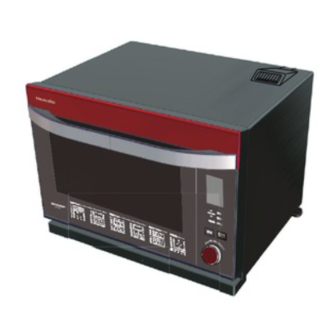
AX-GX2T(R)
AX-GX2T(W)
This document has been published to be used for
after sales service only.
The contents are subject to change without notice.
AXGX2TR
Advertisement
Table of Contents

Related Manuals for Sharp AX-GX2T(R)


Summary of Contents for Sharp AX-GX2T(R)
- Page 1 TopPage AXGX2TR SERVICE MANUAL No.S3201AXGX2TR_T WATER OVEN MODELS AX-GX2T(R) AX-GX2T(W) In the interests of user-safety the oven should be restored to its original condition and only parts identical to those specified should be used. CONTENTS CHAPTER 1. BEFORE SERVICING CHAPTER 6. TEST PROCEDURE CHAPTER 2.
-
Page 2: Table Of Contents
CONTENTS CHAPTER 1. BEFORE SERVICING BOTTOM PLATE ASSEMBLY REMOV- GENERAL IMPORTANT INFORMA- AL..............7-4 TION ............1-1 [10] ENGINE UNIT REMOVAL......7-4 CAUTION MICROWAVE RADIATION ..1-1 [11] TUBE PUMP ASSEMBLY REMOVAL..7-5 WARNING.......... -
Page 3: Chapter 1. Before Servicing
[1] GENERAL IMPORTANT INFORMATION This Manual has been prepared to provide Sharp Corp. Service engineers with Operation and Service Information. It is recommended that service engineers carefully study the entire text of this manual, so they will be qualified to render satisfactory customer ser- vice. -
Page 4: Chapter 2. Warning To Service Personnel
CHAPTER 2. WARNING TO SERVICE PERSONNEL Service Manual The ovens contain circuitry capable of producing very high voltage and current, contact with following parts may result in a severe, possibly fatal, electrical shock. (Example) Inverter unit, Magnetron, High Voltage Harness etc.. Read the Service Manual carefully and follow all instructions. -
Page 5: After Repairing
7. Reconnect the high voltage wire to the magnetron terminal after discharging. WARNING: Use the pliers that the portions of their handles are insulated completely to avoid an electric shock. 8. Reconnect all leads removed from components during testing. 9. Reinstall the outer case and the back plate assembly. 10.Reconnect the power supply cord after the outer case and the back plate assembly are installed. -
Page 6: Chapter 3. Precautions For Using Lead-Free Solder
CHAPTER 3. PRECAUTIONS FOR USING LEAD-FREE SOLDER Service Manual Employing lead-free solder The “Main PWB” of this model employs lead-free solder. This is indicated by the “LF” symbol printed on the PWB and in the service manual. The suf- fixletter indicates the alloy type of the solder. Example: Indicates lead-free solder of tin, silver and copper Indicates lead-free solder of tin, copper and nickel... -
Page 7: Chapter 4. Product Description
CHAPTER 4. PRODUCT DESCRIPTION Service Manual [1] SPECIFICATIONS ITEM DESCRIPTION 110 Volts Power Requirements 60 Hertz Single phase, 3 wire grounded Microwave 1400W 13.0A Power Consumption Oven/Grill 1410W 12.8A Steam 930W 8.4A *800 W nominal of RF microwave energy ( Microwave Power Output 500 W nominal of RF microwave energy (Steady) Operating frequency 2450 MHz... -
Page 8: Oven Components Illustration
[2] OVEN COMPONENTS ILLUSTRATION 1. OVEN 4 – 2... - Page 9 4 – 3...
- Page 10 2. CONTROL PANEL 4 – 4...
- Page 11 4 – 5...
- Page 12 • If the engine unit is replaced, carry out the treatment after engine unit replacement on page 7-5.This page shows how to operate in " “(steam cooking) which is used at the treatment . 4 – 6...
- Page 13 • How to carry out " "(citrate washing) Carry out " "(citrate washing) if the display unit is replaced. 4 – 7...
-
Page 14: Chapter 5. Operation
CHAPTER 5. OPERATION Service Manual [1] Water supply/drainage schematic 1. When installing the reservoir ENGINE UNIT ASSEMBLY Water level sensor Water level unit Water supply tube to the engine as- FEED-WATER RESERVOIR sembly TUBE PUMP DEW TRAY Inserting the reservoir delivers water to the water level unit. 2. - Page 15 3. When removing the reservoir Remained water in the tube and the engine is not discharged even with the reservoir removed. Removing the reservoir discharges remained water in the water level unit to the dew tray. 4. When operating the oven in order to discharge remained water in the engine unit assembly and tube (“Drain water”...
-
Page 16: Operation Of Electric Parts In Each Heating Mode
[2] Operation of electric parts in each heating mode 5 – 3... -
Page 17: Off Condition
*1 After the end of cooking, when the door is kept closed and the temperature is high,the motor will continue to rotate until the temperature falls to the constant temperature. If the door is opened, the motor will rotate for 10 min. *2 The heater will be turned on and off by the temperature control. -
Page 18: Chapter 6. Test Procedure
CHAPTER 6. TEST PROCEDURE Service Manual [1] MAGNETRON (MG) TEST NEVER TOUCH ANY PART IN THE CIRCUIT WITH YOUR HAND OR AN INSULATED TOOL WHILE THE OVEN IS IN OPERATION. CARRY OUT 3D CHECKS. Isolate the magnetron from the high voltage circuit by removing all leads connected to the filament terminal. To test for an open circuit filament use an ohmmeter to make a continuity test between the magnetron filament terminals, the meter should show a reading of less than 1 ohm. -
Page 19: Secondary Interlock Switch And Primary Interlock System Test
1000g 1000g 1000g T1 C T2 C Heat up for 55 sec. [2] SECONDARY INTERLOCK SWITCH AND PRIMARY INTERLOCK SYSTEM TEST 1. SECONDARY INTERLOCK SWITCH 1. Disconnect the power supply cord, and then remove the outer case and the back plate assembly. 2. -
Page 20: Monitor Switch Test
8. Disconnect the wire leads from the fan thermal cut out. 9. Connect the ohmmeter to the red/red terminal of the convection heater and one of the terminal of the convection thermal cut-out. By doing so, the state of the relay contacts using a ohmmeter can be checked. The meter should indicate an open circuit. Because the relay contacts should be open. -
Page 21: Checking Temperature In The Convection (Oven) Mode
[5] CHECKING TEMPERATURE IN THE CONVECTION (Oven) MODE The following test procedure should be carried out with the oven is a fully assembled condition (outer case fitted). It is difficult to measure the exact temperature in the convection oven. An accurate thermocouple type temperature tester must be used. A low priced bi-metal type thermometer is not reliable or accurate. -
Page 22: How To Check In The Event Of An Error
[7] How to check in the event of an error NOTE: HOW TO SET THE TEST MODE (Power on and door closed ) [OPEN DOOR] Version No. is displayed. (Test number is selected by encoder) [or push direct select key] Within 2 sec. - Page 23 2) Check of tube pump performance Hole of the angle base for the motor Measure the weight of the water tank filled with of the tube pump unit water to water level 2.(this weight is A) Set the water tank to the set and power ON. Start 11-minute steaming operation.
- Page 24 3. How to check sensor (oven thermistor) performance Power ON the main body. (See How to set test mode on page 6-5) Set the test mode to 03. Press the START key. Does a measured value for the oven thermistor change as oven heating proceeds? Is the measured value within ±10 bits with respect to the C01: Proceed to checking the oven thermistor for failure.
- Page 25 6. CO5 Engine high temperature failure Is the connectors between the engine thermistor, board and engine mounting section Connect/repair the connector(s) or replace the disconnected or short circuited? thermistor/harness. Measure the engine thermistor resistance using a tester with the thermistor connector pulled out of the board.
-
Page 26: Check And Remedy In The Event Of Malfunction
[8] Check and remedy in the event of malfunction 1. List I Before starting the P.W.B. unit replacement, make sure to refer to “Before replacing the Printed Wiring Board” in page 2-2. Operation Trouble Action No display Has the oven been not operated for 1~30 minutes or more? YES: Open and close the door. - Page 27 2. Check in the event of a fuse 20A blowing When the fuse F10A was blown, observe the following instruction: There are many high voltage components in the oven, therefore, except for performing operational check, unplug the power cable before starting work.
- Page 28 4. How to check input voltage at the primary terminal of the inverter board Measure voltage between the terminal (BLU/BLU) and the terminal (RED) of the inverter unit. Terminal (BLU/BLU) of the inverter unit Terminal (RED) of the inverter unit 6 –...
-
Page 29: Test Mode
[9] TEST MODE How to operate test mode (Power on and door closed ) [OPEN DOOR] Version No. is displayed. (Test number is selected by encoder) [or push direct select key] Within 2 sec. Test name Detail of test Output Example of display A/D data monitor Following A/D data is displayed. - Page 30 Test mode output Example of display Detail of test monitor mode Monitor key, 60times speed key and stage cancel key are available until power turn off. Inverter unit Checking Without cleaning cycle FM (OL),AM Humidity sensor check without Detected Humidity Microwave mode works for 1 min and display shows Humidity sensor level.
- Page 31 The detail of judgment test no.10) Antena motor Display Error timing Water level sensor Engine thermistor umidity sensor or switch immediate steam heating not judged not judged Humidity sensor is defect. micro heating works for 16 sec not judged not judged not judged Antenna motor or switch is defect.
-
Page 32: Chapter 7. Component Replacement And Adjustment Procedure Warnings
2) Open the door and block it open. 3) Sharp edge: 3) Wait for 60 seconds to discharge the high voltage ca- pacitors of the inverter unit. Bottom plate, Oven cavity, Waveguide flange and other metallic plate. -
Page 33: Door Assembly Replacement
5. Remove the two (2) screws holding the back plate to the rear 6. Remove the four (4) screws fixing the back plate. angle. 7. Now, the back plate with exhaust cover is free. [4] DOOR ASSEMBLY REPLACEMENT 1. REMOVAL NOTE: Be careful not to make the 12-pin harness caught in the square hole of the oven. -
Page 34: Door Adjustment
4. Carry out the procedure of item 3 around all the circumferences of NOTE: 1) Do not scratch the door cover and the door packing. the door cover opening. 2) After the door and the oven are assembled, carry out the 5. -
Page 35: Door Sensing Switch, Secondary Interlock Switch And Monitor Switch Adjustment
[8] DOOR SENSING SWITCH, SECONDARY INTERLOCK SWITCH AND MONITOR SWITCH ADJUSTMENT 1. Adjustment 7. Secure the screws firmly. 8. Check all of the switches operation. If each switch plunger has not If the door sensing switch, secondary interlock switch and monitor been pushed with the door closed, loosen the screws and adjust switch do not operate properly due to a misadjustment, the following the position of the latch base angle. -
Page 36: Tube Pump Assembly Removal
6. Now, the capacitors of the inverter unit are discharged. 1. At first, fill the tank assembly with water and carry out WARNING: Use the pliers that the portions of their handles are “ (steam cooking)” with manual operation for about five (5) insulated completely to avoid an electric shock. -
Page 37: Convection Unit Assembly
7. Reconnect the high voltage wire to the magnetron terminal after 11. Remove the latch base angle. discharging. 12.Remove the tube pump assembly, referring to “TUBE PUMP WARNING: Use the pliers that the portions of their handles are ASSEMBLY REMOVAL”. insulated completely to avoid an electric shock. -
Page 38: Sirocco Motor Removal
[15] SIROCCO MOTOR REMOVAL 1. Disconnect the power supply cord. Steam duct ORG 2. Wait for 60 seconds to discharge the high voltage capacitors of the inverter unit. 3. Remove the outer case cabinet, referring to “OUTER CASE REMOVAL”. Steam duct cover ORG 4. -
Page 39: Inverter Unit Assembly Removal
[18] INVERTER UNIT ASSEMBLY REMOVAL 1. Disconnect the power supply cord, and then remove the outer case 7. Remove the bottom plate, referring to “BOTTOM PLATE and the back plate assembly. REMOVAL”. 2. Open the door and block it open. 8. -
Page 40: Chapter 8. Microwave Measurement
CHAPTER 8. MICROWAVE MEASUREMENT Service Manual After adjustment of door latch switches, monitor switch and door are completed individually or collectively, the following leakage test must be per- formed with a survey instrument and it must be confirmed that the result meets the requirements of the performance standard for microwave oven. REQUIREMENT The safety switch must prevent microwave radiation emission in excess of 5mW/cm at any point 5cm or more from external surface of the oven. -
Page 41: Chapter 9. Circuit Diagrams
CHAPTER 9. CIRCUIT DIAGRAMS Service Manual [1] PICTORIAL DIAGRAM 1. CONTROL UNIT from Touch Control Transformer JP13 CF100 D I P CN-H JP14 JP15 RY11 VRS1 JP16 2.5A FUSE1 JP17 JP28 JP18 JP29 JP20 JP22 JP30 JP32 JP41 JP31 JP39 JP40 JP35 JP36... - Page 42 3. OTHER COMPONENTS LATCH SWITCHES Door Sensing Power Supply Cord Switch COM. EARTH Secondary Interlock Switch Monitor Switch WL joint upper (Water sensor) INVERTER UNIT RED RED NOISE FILTER UNIT Ground CN-A Pump motor Thermal cut-out (Engine) WHT/ WHT GRY / BLU Pump motor Main harness Control harness...
- Page 43 Convection motor Convection motor Thermal cut-out (Convection) RED/ Convection heater Thermal cut-out (Fan) Magnetron Connectors to the antenna motor harness and antenna switch harness Control harness Heat cover R assembly Main harness Bottom plate assembly 9 – 3...
- Page 44 Antenna motor and antenna switch BLK for antenna switch NO. terminal WHT for antenna RED for antenna motor terminal motor terminal BLU for antenna switch COM. terminal Antenna motor Purse lock LL and wire holder Wire holder Purse lock LL Inverter unit assembly Control unit...
-
Page 45: Main Circuit
[2] MAIN CIRCUIT CONVECTION FAN MOTOR THERMAL CUT-OUT THERMAL CUT-OUT AC 110V 60HZ T/C TRANSFORMER INVERTER PRIMARY UNIT FUSE INTERLOCK RELAY VRS1 RY10 CR10 POWER RY11 SAVING RELAY ENGINE CONTROL UNIT THERMAL CUT-OUT NOISE FILTER UNIT WATER SENSOR COOLING EXHAUST VENTILATION HUMIDITY SENSOR (DC24V... -
Page 46: Control Unit Circuit
[4] CONTROL UNIT CIRCUIT 9 – 6... -
Page 47: Display Unit Circuit
[5] DISPLAY UNIT CIRCUIT 9 – 7... -
Page 48: Parts List
PartsGuide PARTS LIST WATER OVEN MODELS AX-GX2T(R) AX-GX2T(W) Parts marked "*" may cause undue microwave exposure. Parts marked " " are used in voltage more than 250V. CONTENTS OVEN PARTS ACCESSORY PARTS AND PACKING CABINET PARTS OTHER PARTS DOOR PARTS INDEX HOW TO ORDER REPLACEMENT PARTS To have your order filled promptly and correctly, please... - Page 49 [1] OVEN PARTS 9-47 1-28 8-153 8-74 8-39 8-104 9-15 8-78 8-42 8-86 9-18 9-47 9-15 9-19 8-45 8-49 8-48 8-47 9-15 1-30 9-17 8-15 9-33 8-41 8-46 8-28-1 9-15 8-43 8-28 8-77 8-72 9-14 9-12 8-44 9-20 8-40 9-24 8-148 8-109 9-20...
- Page 50 PRICE PART PARTS CODE DESCRIPTION RANK MARK RANK [1] OVEN PARTS Electric parts CHET-A027WRKZ Engine unit assembly (ENGINE UNIT ASSY) Thermistor (Engine) (THERMISTOR) FH-HZA110WREZ FH-HZA100WREZ Thermistor (Engine) (THERMISTOR) (Interchangeable) RTHM-A149WRZZ Thermal cut-out (Engine) (SH THERMOSTAT) RTHM-A144WRZZ Thermal cut-out (Engine) (SH THERMOSTAT) (Interchangeable) RTHM-A132WRZZ Thermal cut-out (Fan) (THERMAL CUT OUT) RTHM-A116WRE0...
- Page 51 PRICE PART PARTS CODE DESCRIPTION RANK MARK RANK [1] OVEN PARTS 8-76 CUSSION PCUS-A216WREZ 8-77 PCUS-A217WREZ CUSSION 8-78 PCUS-A218WREZ CUSSION 8-80 PGLSPA743WREZ LAMP GLASS 8-81 PPAC-A119WREZ LAMP PACKING 8-82 ENGINE PACKING B PPAC-A133WREZ 8-83 PSKR-A504WRPZ BOTTOM SHIELD PLATE 8-84 PSLDHA302WRPZ HEAT COVER BOTTOM 8-85 PSLDHA276WRPZ...
- Page 52 [2] CABINET PARTS 9-34 9-34 8-98 8-68 9-34 9-37 8-65 8-66 8-31 9-32 8-30 1-26 8-67 9-36 8-77 8-54 1-20 8-62 8-63 8-95 1-14 8-95 8-29 8-89 9-24 8-56 8-72 9-27 8-94 8-58 9-46 8-61 8-115 1-10 9-24 1-11 8-19 9-34 9-46 9-32...
- Page 53 PRICE PART PARTS CODE DESCRIPTION RANK MARK RANK [2] CABINET PARTS Accessory and packing DPWBFC618WRUZ Inverter unit assembly (INV UNIT ASSY) QACC-A137WRZZ Power supply cord (POWER SUPPLY CORD) DPWB-B088DRKZ Control unit (CONTROL UNIT) 1-10 QFS-BA009WRE0 Fuse 20A (FUSE 20A) 1-11 FPWBFA457WRKZ Noise filter unit (NOISE FILTER) 1-14...
- Page 54 [3] DOOR PARTS...
- Page 55 PRICE PART PARTS CODE DESCRIPTION RANK MARK RANK [3] DOOR PARTS DPWB-B038DRKZ1 Display unit (DISPLAY UNIT) Door parts START BUTTON ASSEMBLY [R] FBTN-A235WRKZ FBTN-A239WRKZ START BUTTON ASSEMBLY [W] FBTN-A233WRKZ DEFROST BUTTON ASSEMBLY [R] JBTN-B696WRRZ DEFROST BUTTON [W] FBTN-A234WRKZ ENTER BUTTON ASSEMBLY [R] FBTN-A238WRKZ ENTER BUTTON ASSEMBLY [W] HDECAA673WRRZ...
- Page 56 [4] ACCESSORY PARTS AND PACKING DEW TRAY ASSY 90-20 90-10 90-10 90-14 90-11 90-6 90-17 90-7 for only AX-GX2T(R) 90-2 90-19 90-12 90-18 90-9 90-16 90-10 90-1 90-12 90-2 90-12 90-8 90-3 90-5 90-13...
- Page 57 PRICE PART PARTS CODE DESCRIPTION RANK MARK RANK [4] ACCESSORY PARTS AND PACKING 90-1 PSRA-A080WRTZ SPLASH GUARD 90-2 PSRA-A074WRHZ BASE TRAY 30L 90-3 ACCESSORY CASE SPADFA658WREZ 90-5 SSAKHA117WREZ WRAP COVER 90-6 TCADCB088WRRZ COOK BOOK 90-9 UAMI-A177WREZ RACK 30L 90-7 SPAKHA035WREZ CABINET COVER [R] 90-8 SPADBB728WREZ...
- Page 58 INDEX PRICE PART PRICE PART PARTS CODE PARTS CODE RANK MARK RANK RANK MARK RANK LANGKB426WRPZ 1-8-123 [ C ] LANGKB449WRPZ 1-8-39 CHET-A027WRKZ 1-1-1 LANGKB492WRFZ 1-8-121 CPADBA456WRKZ 4-90-10 LANGKB493WRWZ 3-6-17 [ D ] LANGQA784WRPZ 1-8-15 DOVN-A794WRKZ 1-8-3 LANGQA792WRPZ 1-8-55 DPWB-B038DRKZ1 3-1-4 LBND-A033WREZ 1-8-131...
- Page 59 PRICE PART PRICE PART PARTS CODE PARTS CODE RANK MARK RANK RANK MARK RANK PDUC-B244WRFZ 2-8-31 SSAKHA032WRE0 4-90-14 PFPF-A301WREZ 1-8-47 SSAKHA087WREZ 4-90-12 PGID-A119WRFZ 2-8-9 SSAKHA117WREZ 4-90-5 PGID-A120WRFZ 2-8-10 SSAKHA124WREZ 4-90-16 PGID-A121WRFZ 2-8-9 [ T ] PGID-A122WRFZ 2-8-10 TCADCB088WRRZ 4-90-6 PGLSPA743WREZ 1-8-80 TCAUAA368WRRZ 2-8-68...
- Page 60 EndPage COPYRIGHT © 2012 BY SHARP CORPORATION ALL RIGHTS RESERVED. No part of this publication may be reproduced, stored in retrieval systems, or transmitted in anyform or by any means, electronic, mechanical, photocopying, re- cording, or other wise, without prior written permission...
Need help?
Do you have a question about the AX-GX2T(R) and is the answer not in the manual?
Questions and answers