Table of Contents
Advertisement
Quick Links
TopPage
In the interests of user-safety the oven should be restored to its original condition and only parts identical to those
specified should be used.
CHAPTER 1. BEFORE SERVICING
CHAPTER 2. WARNING TO SERVICE PERSONNEL
CHAPTER 3. PRECAUTIONS FOR USING LEAD-
FREE SOLDER
CHAPTER 4. PRODUCT DESCRIPTION
CHAPTER 5. OPERATION
SERVICE MANUAL
MODEL
CONTENTS
CHAPTER 6. TEST PROCEDURE
CHAPTER 7. COMPONENT REPLACEMENT AND
ADJUSTMENT PROCEDURE
CHAPTER 8. MICROWAVE MEASUREMENT
CHAPTER 9. CIRCUIT DIAGRAMS
Parts List
AX1500J(S)
S7908AX15PJS/
SUPER STEAM OVEN
AX-1500J(S)
This document has been published to be used for
after sales service only.
The contents are subject to change without notice.
Advertisement
Chapters
Table of Contents

Related Manuals for Sharp AX-1500J


Summary of Contents for Sharp AX-1500J
- Page 1 TopPage AX1500J(S) SERVICE MANUAL S7908AX15PJS/ SUPER STEAM OVEN AX-1500J(S) MODEL In the interests of user-safety the oven should be restored to its original condition and only parts identical to those specified should be used. CONTENTS CHAPTER 1. BEFORE SERVICING CHAPTER 6. TEST PROCEDURE CHAPTER 2.
-
Page 2: Table Of Contents
CONTENTS CHAPTER 1. BEFORE SERVICING DOOR SENSING SWITCH, SECOND- GENERAL IMPORTANT INFORMA- ARY INTERLOCK SWITCH AND MONI- TION ............1-1 TOR SWITCH REPLACEMENT ....7-3 CAUTION MICROWAVE RADIATION ..1-1 DOOR SENSING SWITCH, SECOND- WARNING.......... -
Page 3: Chapter 1. Before Servicing
[1] GENERAL IMPORTANT INFORMATION This Manual has been prepared to provide Sharp Corp. Service engineers with Operation and Service Information. It is recommended that service engineers carefully study the entire text of this manual, so they will be qualified to render satisfactory customer ser- vice. -
Page 4: Chapter 2. Warning To Service Personnel
AX1500J(S) CHAPTER 2. AX1500J(S) WARNING TO SERVICE PERSONNEL The ovens contain circuitry capable of producing very high voltage and current, contact with following parts may result in a severe, possibly fatal, electrical shock. (Example) Inverter unit, Magnetron, High Voltage Harness etc.. Read the Service Manual carefully and follow all instructions. -
Page 5: After Repairing
AX1500J(S) 7. Reconnect the high voltage wire to the magnetron terminal after discharging. WARNING: Use the pliers that the portions of their handles are insulated completely to avoid an electric shock. 8. Reconnect all leads removed from components during testing. 9. -
Page 6: Chapter 3. Precautions For Using Lead-Free Solder
AX1500J(S) CHAPTER 3. AX1500J(S) PRECAUTIONS FOR USING LEAD-FREE SOLDER Employing lead-free solder The “Main PWB” of this model employs lead-free solder. This is indicated by the “LF” symbol printed on the PWB and in the service manual. The suffix letter indicates the alloy type of the solder. Example: Indicates lead-free solder of tin, silver and copper Using lead-free wire solder... -
Page 7: Chapter 4. Product Description
AX1500J(S) CHAPTER 4. AX1500J(S) PRODUCT DESCRIPTION [1] SPECIFICATIONS ITEM DESCRIPTION 230 - 240 Volts Power Requirements 50 Hertz Single phase, 3 wire grounded Microwave 1.16KW (Steady) 5.1A (Steady) 1.38KW (Initial) 6.1A (Initial) Power Consumption Convection 1.55KW 6.5A *800 W nominal of RF microwave energy (IEC Test procedure) Microwave Power Output 600 W nominal of RF microwave energy (Steady) Operating frequency 2450 MHz... -
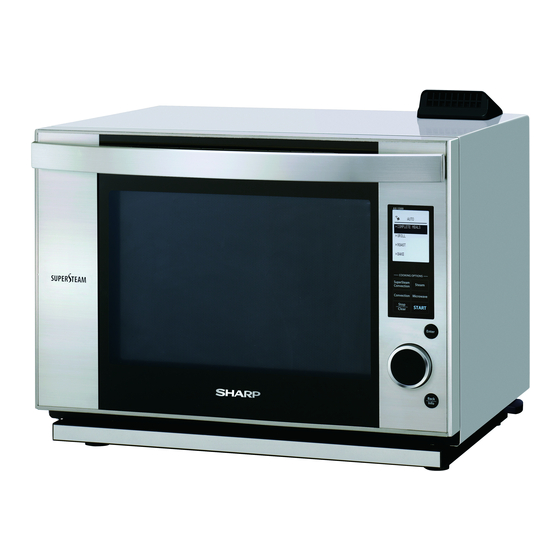
Page 8: Oven Components Illustration
AX1500J(S) [2] OVEN COMPONENTS ILLUSTRATION 1. OVEN 1 Ventilation openings 2 Door open handle 3 LCD display 4 Control panel 5 Oven lamp 6 Upper position 7 Lower position 8 Water tank lid 9 Water tank 10 Door seals and sealing surfaces 11 Latches 12 Ceramic oven floor... -
Page 9: Operation
AX1500J(S) 2. CONTROL PANEL TOUCH CONTROL PANEL LAYOUT 1. SuperSteam Convection pad Press to select SuperSteam Convection cooking.SuperSteam Convection has 2 options; "automatic cooking" and "manual cooking". 2. Convection pad Press to select Manual Convection cooking. No automatic cooking mode for Convection. 3. -
Page 10: Chapter 5. Operation
AX1500J(S) CHAPTER 5. AX1500J(S) OPERATION [1] Water supply/drainage schematic 1. When installing the reservoir ENGINE UNIT ASSEMBLY Water level sensor Water level unit Water supply tube to the engine as- FEED-WATER RESERVOIR sembly TUBE PUMP DEW TRAY Inserting the reservoir delivers water to the water level unit. 2. - Page 11 AX1500J(S) 3. When removing the reservoir Remained water in the tube and the engine is not discharged even with the reservoir removed. Removing the reservoir discharges remained water in the water level unit to the dew tray. 4. When operating the oven in order to discharge remained water in the engine unit assembly and tube (“Drain water”...
-
Page 12: On/Off Operation Of Electric Parts In Each Heating Mode
AX1500J(S) [2] On/Off operation of electric parts in each heating mode Signal Parts Heating modes Microwave Convection Supersteam Steam Inverter unit Primary interlock relay Engine heater Convection heater Supper Steam heater Fan motor (AC motor) Out put Cooling fan motor (DC motor) Ventilation fan motor (DC motor) Sirocco fan motor (Exhaust) Convection motor... -
Page 13: Chapter 6. Test Procedure
AX1500J(S) CHAPTER 6. AX1500J(S) TEST PROCEDURE [1] MAGNETRON (MG) TEST NEVER TOUCH ANY PART IN THE CIRCUIT WITH YOUR HAND OR AN INSULATED TOOL WHILE THE OVEN IS IN OPERATION. CARRY OUT 3D CHECKS. Isolate the magnetron from the high voltage circuit by removing all leads connected to the filament terminal. To test for an open circuit filament use an ohmmeter to make a continuity test between the magnetron filament terminals, the meter should show a reading of less than 1 ohm. -
Page 14: Secondary Interlock Switch And Primary Interlock System Test
AX1500J(S) 1000g 1000g 1000g T1 C T2 C Heat up for 55 sec. [2] SECONDARY INTERLOCK SWITCH AND PRIMARY INTERLOCK SYSTEM TEST 1. SECONDARY INTERLOCK SWITCH 1. Disconnect the power supply cord, and then remove the outer case and the back plate assembly. 2. -
Page 15: Monitor Switch Test
AX1500J(S) 8. Disconnect the wire leads from the fan thermal cut out. 9. Connect the ohmmeter to the red/red terminal of the convection heater and one of the terminal of the convection thermal cut-out. By doing so, the state of the relay contacts using a ohmmeter can be checked. The meter should indicate an open circuit. Because the relay contacts should be open. -
Page 16: Checking Temperature In The Convection (Oven) Mode
AX1500J(S) [5] CHECKING TEMPERATURE IN THE CONVECTION (Oven) MODE The following test procedure should be carried out with the oven is a fully assembled condition (outer case fitted). It is difficult to measure the exact temperature in the convection oven. An accurate thermocouple type temperature tester must be used. A low priced bi-metal type thermometer is not reliable or accurate. -
Page 17: How To Check In The Event Of An Error
AX1500J(S) [7] How to check in the event of an error NOTE: HOW TO SET THE TEST MODE (Power ON/door closed state) [STOP/CLEAR] [SUPERSTEAM CONVECTION] [MICROWAVE] [OPEN DOOR] (Set the number (initial number: 04) by [ENCODER] [START] Within 1 sec. Within 1 sec. - Page 18 AX1500J(S) 2) Check of tube pump performance Hole of the angle base for the motor Measure the weight of the water tank filled with of the tube pump unit water to water level 2.(this weight is A) Set the water tank to the set and power ON. Start 11-minute steaming operation.
- Page 19 AX1500J(S) 3. How to check sensor (oven thermistor) performance Power ON the main body. Set the test mode to 03. (See How to set test mode on page 6-5) Press the START key. Does a measured value for the oven thermistor change as oven heating proceeds? Is the measured value within ±10 bits with respect to the EE01: Proceed to checking the oven thermistor for failure.
- Page 20 AX1500J(S) 6. EEO5 Engine high temperature failure Is the connectors between the engine thermistor, board and engine mounting section Connect/repair the connector(s) or replace the disconnected or short circuited? thermistor/harness. Measure the engine thermistor resistance using a tester with the thermistor connector pulled out of the board.
-
Page 21: Check And Remedy In The Event Of Malfunction
AX1500J(S) [8] Check and remedy in the event of malfunction 1. List ✩ Before starting the P.W.B. unit replacement, make sure to refer to “Before replacing the Printed Wiring Board” in page 2-2. Operation Trouble Action No display Has the oven been not operated for 3 minutes or more? YES: Open and close the door. - Page 22 AX1500J(S) 3. Check in the event of no microwave cooking Check of high voltage sections is very dangerous. Therefore, after the inverter boards (M and AC3) and 230 - 240V at the primary terminal are con- firmed to be satisfactory, disconnect the main power and wait for at least one (1) minute before starting the check. Check of individual components is done with the high voltage circuit wiring disconnected.
-
Page 23: Test Mode
AX1500J(S) [9] TEST MODE How to operate test mode (power on and door closed) [STOP/CLEAR] [SUPER STEAM CONVECTION] [MICROWAVE] [door open] (test number is selected by encoder [initial number 04]) [START] or [push direct select key] within within within 1sec 1sec 1sec Test Name... -
Page 24: Chapter 7. Component Replacement And Adjustment Procedure Warnings
2) Open the door and block it open. 3) Wait for 60 seconds to discharge the high voltage ca- 3) Sharp edge: Bottom plate, Oven cavity, Waveguide flange and pacitors of the inverter unit. other metallic plate. -
Page 25: Door Assembly Replacement
AX1500J(S) 5. Remove the two (2) screws holding the back plate to the rear 6. Remove the four (4) screws fixing the back plate. angle. 7. Now, the back plate with exhaust cover is free. [4] DOOR ASSEMBLY REPLACEMENT 1. REMOVAL NOTE: Be careful not to make the 12-pin harness caught in the square hole of the oven. -
Page 26: Door Sensing Switch, Secondary Interlock Switch And Monitor Switch Replacement
AX1500J(S) 2. Insert a spacer of 0.8mm in thickness between the door sealer sec- NOTE: In order to prevent deformation of parts, lay a soft mat and tion (lower portion) and the front plate. then turn the unit on it. 1. -
Page 27: Bottom Plate Assembly Removal
AX1500J(S) 2. After adjustment, check the following. 2. The door sensing switch and the secondary interlock switch open within 3.0mm gap between the oven door and cavity face. 1. In and out play of the door remains less than 0.5 mm when in the 3. -
Page 28: Dc Fan Motor (Ventilation) Removal
AX1500J(S) WARNING: Use the pliers that the portions of their handles are 16.Pull the right panel upward and remove it from the front plate of the insulated completely to avoid an electric shock. oven. 7. Remove the four (4) screws holding the side angle. 17.Remove the one (1) screw fixing the tank cover to the front plate of the oven from the front. -
Page 29: Magnetron Replacement
AX1500J(S) NOTE: If the ring, when removed, has been deformed, replace it with 8. Now, the convection motor is free new one. Using any deformed ring causes unbalanced rota- tion of the cooling fan. [14] MAGNETRON REPLACEMENT 1. REMOVAL 10.Remove the two (2) screws holding the magnetron to the waveguide. -
Page 30: Circuit Diagrams
AX1500J(S) 8. Remove the one (1) screw holding the filter cover to the bottom 7. Reinstall the bottom plate assembly to the oven. plate. 8. Reconnect all leads removed from components during testing. 9. Straighten the tab of the bottom plate holding the filter cover to the 9. - Page 31 AX1500J(S) CHAPTER 8. AX1500J(S) MICROWAVE MEASUREMENT After adjustment of door latch switches, monitor switch and door are completed individually or collectively, the following leakage test must be per- formed with a survey instrument and it must be confirmed that the result meets the requirements of the performance standard for microwave oven. REQUIREMENT The safety switch must prevent microwave radiation emission in excess of 5mW/cm at any point 5cm or more from external surface of the oven.
-
Page 32: Pictorial Diagram
AX1500J(S) CHAPTER 9. AX1500J(S) CIRCUIT DIAGRAMS [1] PICTORIAL DIAGRAM 1. CONTROL UNIT AH Sensor from Touch Control Transformer JP13 CF100 D I P CN-H JP14 JP15 RY11 VRS1 JP16 2.5A FUSE1 JP17 JP28 JP18 JP29 JP20 JP22 JP30 JP32 JP41 JP31 JP39 JP40... -
Page 33: Main Circuit
AX1500J(S) 3. OTHER COMPONENTS LATCH SWITCHES INVERTER UNIT Door Sensing BLUE Switch COM. Secondary Interlock Switch CN-A Ground Monitor Power Supply Cord Switch NEUTRAL EARTH WL joint upper LIVE (Water sensor) FUSE Main wire harness BLK or RED NOISE FILTER UNIT [2] MAIN CIRCUIT FAN MOTOR CONVECTION... -
Page 34: Inverter Unit Circuit
AX1500J(S) [3] INVERTER UNIT CIRCUIT T110 L110 BLUE D120 UX-F5B 15W/3.3k D110 D100 R100 Q110 UX-F5B CT100 D121 A063DR R101 RD5.1ESAB1 TH111 3.6kF 1/4W 1/2W1.2K PD100 (HIC1) CN-A 9 – 3... -
Page 35: Control Unit Circuit
AX1500J(S) [4] CONTROL UNIT CIRCUIT 3.32KD 3.57KD 50V/0.1u 50V/10u HZ12B1 2.2K 1/4W 9 – 4... -
Page 36: Display Unit Circuit
AX1500J(S) [5] DISPLAY UNIT CIRCUIT 9 – 5... - Page 37 AX1500J(S) 9 – 6...
-
Page 38: Parts List
PartsGuide PARTS LIST SUPER STEAM OVEN HOW TO ORDER REPLACEMENT PARTS To have your order filled promptly and correctly, please furnish the following information. AX-1500J(S) 1. MODEL NUMBER MODEL 2. REF. NO. 3. PART NO. 4. DESCRIPTION Parts marked "*" may cause undue microwave exposure. - Page 39 AX1500J(S) [1] OVEN PARTS 9-16 1-28 8-153 8-74 8-39 8-104 9-15 8-42 8-78 8-86 9-18 9-16 9-15 9-19 8-45 8-49 8-48 8-47 9-15 1-30 9-17 8-15 9-33 8-41 8-46 8-28-1 9-15 8-43 8-28 8-77 8-72 9-14 9-12 8-44 9-20 8-40 9-33 9-24 8-148...
-
Page 40: Description
AX1500J(S) PRICE PART PARTS CODE DESCRIPTION RANK MARK RANK [1] OVEN PARTS ELECTRIC PARTS Engine unit assembly CHET-A015WRKZ Thermistor (Engine) FH-HZA100WREZ Thermal cut out (Engine) RTHM-A149WRZZ Thermal cut out (Engine) (Interchangeable) RTHM-A144WRZZ Thermal cut out (Fan) RTHM-A132WRZZ Thermal cut-out (Fan) (Interchangeable) RTHM-A116WRE0 Thermal cut-out (Fan) (Interchangeable) RTHM-A148WRZZ... - Page 41 AX1500J(S) PRICE PART PARTS CODE DESCRIPTION RANK MARK RANK [1] OVEN PARTS 8-88 Inverter sheald plate PZETPA001WRFZ 8-94 Cushion PCUS-A234WREZ 8-100 Steam duct ag LANGKB394WRPZ 8-101 Steam duct cover ORG PCOV-A142WRFZ 8-102 Cushion PCUS-A222WREZ 8-104 PCUS-A237WREZ Cushion 8-107 Cushion PCUS-A261WREZ 8-108 Joint duct Front PDUC-B136WRFZ...
-
Page 42: Cabinet Parts
AX1500J(S) [2] CABINET PARTS 8-75 9-34 9-34 8-98 8-112 8-135 8-136 9-34 9-37 8-136 8-65 8-66 8-31 9-32 8-30 1-26 8-67 9-36 8-77 8-54 1-20 8-62 8-63 8-95 8-95 8-29 8-89 9-24 8-56 8-72 9-27 1-14 8-94 8-58 9-46 8-61 8-115 1-10 9-24... - Page 43 AX1500J(S) PRICE PART PARTS CODE DESCRIPTION RANK MARK RANK [2] CABINET PARTS ELECTRIC PARTS Inverter unit assembly DPWBFC593WRUZ Power supply cord QACC-A178WRZZ Control unit DPWB-A786DRKZ 1-11 Noise filter unit FPWBFA448WRKZ 1-14 Transformer RTRNPA170DRZZ 1-10 Fuse F10A QFS-CA026WRZZ 1-20 Fan motor RMOTEA462WRZZ Dew tray switch QSW-MA086WRE0...
-
Page 44: Ax1500J(S)
AX1500J(S) [3] DOOR PARTS 6-26 6-32 6-37 6-36 6-32 6-35 6-36 6-10 6-32 6-35 6-31 6-36 6-31 6-32 6-35 6-36 6-22 6-11 6-18 6-13 6-27 6-15 6-31 6-21 6-32 6-16 6-25 6-20 6-23 6-19 6-32 8-105 6-17 8-115 6-12 6-14 PRICE PART PARTS CODE... -
Page 45: Accessory Parts And Packing
AX1500J(S) PRICE PART PARTS CODE DESCRIPTION RANK MARK RANK [3] DOOR PARTS 6-23 Wire protect cover PCOVPA507WRFZ 6-25 Out door glass PGLSPA779WREZ 6-26 Door packing PPAC-A149WREZ 6-27 PWB packing PPAC-A117WREZ 6-31 Screw 3mm x 12mm XEBS730P12000 6-32 XEPS740P10000 Tapping screw (4mm x 10mm) 6-35 Tapping screw (4mm x 10mm) XETS740P10000... -
Page 46: Other Parts
AX1500J(S) PRICE PART PARTS CODE DESCRIPTION RANK MARK RANK [4] ACCESSORY PARTS AND PACKING Drip tray cover GCOVPA021WRFZ Drip tray GCUPPA020WRTZ 90-1 Steam tray (Steam basket) PSRA-A046WRTZ 90-2 Base tray 30l PSRA-A074WRHZ 90-3 Accessary case SPADFA659WREZ 90-4 Wrap cover SSAKA0034WRE0 90-5 Wrap cover SSAKHA116WREZ... -
Page 47: Index
AX1500J(S) INDEX PRICE PART PRICE PART PARTS CODE PARTS CODE RANK MARK RANK RANK MARK RANK LBNDKA180WRPZ 1-8-43 [ C ] LHLD-A334WRFZ 3-6-15 CHET-A015WRKZ 1-1-1 LHLDPA006WRFZ 2-8-7 [ D ] LHLDWA013WRE0 5-8-57 DDORFB396WRKZ LSTPPA294WRFZ 3-6-20 DOVN-A722WRKZ 1-8-3 LX-BZA138WREZ 2-9-3 DPWB-A784DRKZ 3-1-4 LX-BZA144WREZ 1-9-45... - Page 48 AX1500J(S) PRICE PART PRICE PART PARTS CODE PARTS CODE RANK MARK RANK RANK MARK RANK PDUC-B137WRFZ 1-8-109 TCAUHA344WRRZ 2-8-75 PDUC-B139WRFZ 1-8-26 TCAUSA016WRRZ 3-8-105 PFPF-A301WREZ 1-8-47 TINS-A779WRRZ 4-90-15 PGID-A090WRFZ 2-8-9 TINSJA364WRRZ 4-90-20 PGID-A091WRFZ 2-8-10 [ U ] PGIDMA021WRFZ 4-90-16 UAMI-A165WRTZ 4-90-9 PGLSPA743WREZ 1-8-80 [ X ]...
- Page 49 EndPage COPYRIGHT © 2009 BY SHARP CORPORATION ALL RIGHTS RESERVED. No part of this publication may be reproduced, stored in retrieval systems, or transmitted in any form or by any means, electronic, mechanical, photocopying, re- cording, or other wise, without prior written permission of the publisher.
Need help?
Do you have a question about the AX-1500J and is the answer not in the manual?
Questions and answers