Table of Contents
Advertisement
Instruction Manual
D200138X012
June 2010
Fisherr 3582 and 3582i Positioners, 582i
Electro-Pneumatic Converter, and 3583 Valve
Stem Position Transmitters
Contents
. . . . . . . . . . . . . . . . . . . . . . . . . . . . . . .
. . . . . . . . . . . . . . . . . . . . . . . . .
. . . . . . . . . . . . . . . . . . . . . . . . . . . . . .
. . . . . . . . . . . . . . . . . . . . . . . . . . . .
. . . . . . . . . . . . . . . . . . . . . . . . . . . . . . . .
Installation in Hazardous Areas for
for 582i Converter
. . . . . . . . . . . . . . . . . . . . . . . . . . . . . . . . . . .
FM
. . . . . . . . . . . . . . . . . . . . . . . . . . . . . . . . . . . .
. . . . . . . . . . . . . . . . . . . . . . . . . . . . . . . . . .
. . . . . . . . . . . . . . . . . . . . . . . . . . . . . . . . . .
. . . . . . . . . . . . . . . . . . . . . . . . . . . . . . . .
. . . . . . . . . . . . . . . . . . . . . . . . . . . . .
W5498-1
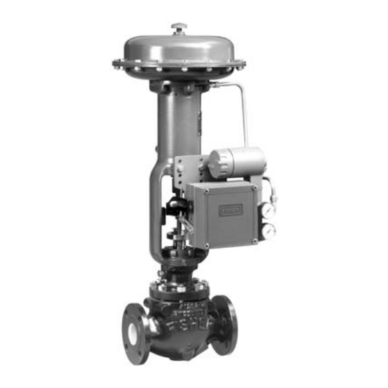
CONTROL VALVE WITH
3582 POSITIONER
Figure 1. Typical Mounting for Fisher 3582 and 3582i Positioners and 3583 Transmitters
www.Fisher.com
. . . . . . . . . . . . . . .
. . . . . . . . . . . . . . . . . . . . . .
. . . . . . . . . . . . . . . . . . . . .
W5499-1
2
2
2
6
6
6
. . . . . . . . . . . . . . . . . . . . . . . . . . . . . . . . . . .
6
7
8
8
8
9
10
10
CONTROL VALVE WITH
3583 TRANSMITTER
3582, 582i, and 3583
. . . . . . . . . . . . . . . . . . . . . . . . . . . . . . .
. . . . . . . . . . . . . . . . . .
. . . . . . . . . . . . . . . . . . . .
. . . . . . . . . . . . . . . . . . . . .
. . . . . . . . . . . . . . . . . . . . . .
. . . . . . . . . . . . . . . . . .
. . . . . . . . . . . . . . . . .
. . . . . . . . . . . . . . . . . . . . . . .
. . . . . . . . . . . . . . . .
. . . . . . . . . . . . . . . . . . . . .
. . . . . . . . . . . . . . . . . . . . . . . . . . .
(continued on page 2)
W8424
CONTROL VALVE WITH
3582i POSITIONER
11
14
15
15
15
15
16
17
18
19
20
. . . . . . . . . .
20
21
Advertisement
Table of Contents

Related Manuals for Emerson Fisher 3582


Summary of Contents for Emerson Fisher 3582
-
Page 1: Table Of Contents
......W5499-1 W5498-1 W8424 CONTROL VALVE WITH CONTROL VALVE WITH CONTROL VALVE WITH 3583 TRANSMITTER 3582 POSITIONER 3582i POSITIONER Figure 1. Typical Mounting for Fisher 3582 and 3582i Positioners and 3583 Transmitters www.Fisher.com... -
Page 2: Introduction
3582NS positioner is qualified operation, calibration, maintenance, and parts commercial grade dedicated. These can be supplied ordering information for Fisher 3582 pneumatic valve as 10CFR, Part 21 items. positioners, the 3582i electro-pneumatic valve positioner, and 3583 pneumatic valve stem position The 3582i is an electro-pneumatic valve positioner, transmitters. - Page 3 Instruction Manual 3582, 582i, and 3583 June 2010 Table 1. Specifications for Fisher 3582 and 3582i Valve Positioners Note: Specifications for 3582 positioners 2.4 bar (35 psig) Supply: 0.64 normal m include 3582A, 3582C, 3582D, 3582G, and (23.8 scfh) 3582NS unless otherwise indicated...
- Page 4 Instruction Manual 3582, 582i, and 3583 June 2010 Table 1. Specifications for Fisher 3582 and 3582i Valve Positioners (Continued) Electrical Classification for 582i Pressure Gauges CSA—Intrinsically Safe, Explosion proof, Type n, 40 mm (1.5 inch) diameter with plastic case and...
- Page 5 Instruction Manual 3582, 582i, and 3583 June 2010 Table 2. Specifications for Fisher 3583 Valve Stem Position Transmitters Input Signal Operating Influence 105 mm (4.125 inches) of valve stem travel; Output signal changes 1.67 percent per bar (0.23 adjustable to obtain full output signal with lesser percent per 2 psig) change in supply pressure stem travels Operative Ambient Temperature Limits...
-
Page 6: Type Number Descriptions
3583, as well as a variety of other products, contact: 3582C—Pneumatic valve positioner without bypass and with automotive tire valves instead of pressure Emerson Process Management gauges. Educational Services, Registration P.O. Box 190; 301 S. 1st Ave. 3582D—Pneumatic valve positioner with bypass and... -
Page 7: Special Instructions For "Safe Use" And
Instruction Manual 3582, 582i, and 3583 June 2010 any installation operations to avoid stem position transmitter, except for the 3582NS personal injury. positioner. For the 3582NS, the 67CFR is separately mounted, not integrally mounted to the positioner. If installing into an existing application, also refer to the WARNING Note at the beginning of the Maintenance... -
Page 8: Csa
Instruction Manual 3582, 582i, and 3583 June 2010 Table 4. Hazardous Area Classifications for Fisher 582i Converter —CSA (Canada) Certification Certification Obtained Entity Rating Temperature Code Enclosure Rating Body Intrinsically Safe Vmax = 30 VDC T4 (Tamb v 71°C) Ex ia IIC T4/T5/T6 per drawing GE28591 Imax = 150 mA T5 (Tamb v 62°C) Ex ia Intrinsically Safe... -
Page 9: Iecex
Instruction Manual 3582, 582i, and 3583 June 2010 Table 6. Hazardous Area Classifications for Fisher 582i Converter —ATEX Certificate Certification Obtained Entity Rating Temperature Code Enclosure Rating II 1 G & D T4 (Tamb v 71°C) Intrinsically Safe T5 (Tamb v 62°C) Ui = 30 VDC T6 (Tamb v 47°C) Ex ia IIC T4/T5/T6... -
Page 10: Nepsi
Intrinsically Safe, Dust & Flameproof, Dust −40_C v Ta v +71_C; T6 (Ta v +71_C) Refer to table 8 for approval information. Contact your Emerson Process Management sales Refer to table 7 for approval information, and figure office for additional “safe use” information. -
Page 11: Mounting
Instruction Manual 3582, 582i, and 3583 June 2010 657, 657MO, 667, 667MO SIZE 80 UP TO 51 mm (2 IN) TRAVEL SIZE 70, 87 UP TO 51 mm (2 IN) TRAVEL 67CFR SIZE 32 657, 657MO, 667, 667MO ALL SIZES SIZE 100 ALL TRAVEL 657MO 657, 657MO, 667, 667MO... - Page 12 Instruction Manual 3582, 582i, and 3583 June 2010 Table 10. Fisher 3582 and 3583 Mounting Information MOUNTING MAXIMUM MAXIMUM MOUNTING ACTUATOR ACTUATOR HOLES TRAVEL PIN TRAVEL PIN TRAVEL TRAVEL HOLES SET NO. POSITION POSITION SET NO. Type Size Inch Type...
- Page 13 Instruction Manual 3582, 582i, and 3583 June 2010 ACTUATOR TRAVEL PIN STEM (KEY 60) STEM STEM 9.5 mm 19.1 mm 12.7 mm CONNECTOR TRAVEL (0.375 Inch) (0.75 Inch) (0.5 Inch) Stem Stem Stem CONNECTOR ARM (KEY 48) Millimeters 29 or less CAP NUT (KEY 62) ROTARY SHAFT...
-
Page 14: Changing Cam Position
MOUNTING PLATE FOR MOUNTING POSITIONER WITH WITH INTEGRALLY MOUNTED FILTER REGULATOR SEPARATELY MOUNTED FILTER REGULATOR Figure 5. Mounting Plates Used with Fisher 3582 Valve Positioners and 3583 Valve Stem Position Transmitters D For Valve Stem Position CASE INDEX MARKS Transmitters: If the arrow on the cam... -
Page 15: Pressure Connections
A factory mounted valve positioner has the valve diameter will suffice in most positioner output piped to the supply connection on applications, check with an Emerson the actuator. If mounting the valve positioner in the Process Management field office and... -
Page 16: Diagnostic Connections
Instruction Manual 3582, 582i, and 3583 June 2010 141.2 139.7 246.1 (5.56) (5.50) (9.69) 119.1 57.2 182.6 (4.69) (2.25) (7.19) OF ACTUATOR 12.7 (.31) (.50) 1/2-14 NPT CONDUIT CONN 8.6 (.34) ∅ HOLES SPACED 17.5 (.69) APART 289.0 (11.38) 3/8-18 NPT 1/4-18 NPT VENT CONN OUTLET CONN... -
Page 17: Vent
Instruction Manual 3582, 582i, and 3583 June 2010 3582i 3582 POSITIONERS GAUGE BODY PROTECTOR STEM PROVIDED BODY BODY WHEN GAUGE IS PROTECTOR SPECIFIED BODY 12B8045-A 3582 VALVE POSITIONERS 12B8046-C A6077−1/IL 3582i VALVE POSITIONER A6078−2/IL Figure 8. Diagnostic Connections the supply medium. Use of natural gas Vent as the supply medium can result in personal injury or property damage... -
Page 18: Electrical Connections For 3582I Valve Positioner
Instruction Manual 3582, 582i, and 3583 June 2010 TERMINAL POSITIONER BLOCK HOUSING CONTROL FIELD WIRING DEVICE 21B2335-D A6012/IL EARTH GROUND Figure 10. Input Equivalent Circuit for Fisher 582i Converter NOTES: FOR TROUBLESHOOTING OR MONITORING OPERATION, AN INDICATING DEVICE CAN BE A VOLTMETER ACROSS A FIELD 250 OHM RESISTOR OR A CURRENT METER. -
Page 19: 582I Converter Installation
582i converter on Note an existing 3582 positioner which has a three-hole mounting pattern. Contact your Emerson Process Management sales office for Isolate the control valve from the line pressure, and application information before release pressure from both sides of the valve body. -
Page 20: Operating Information
Instruction Manual 3582, 582i, and 3583 June 2010 3. Remove the two screws (key 105 in figures 24 or 25) holding the bypass block (key 34A in figures 24 or 25) to the valve positioner case and remove the bypass block. Save the screws to reattach the 582i converter. -
Page 21: Valve Stem Position Transmitter Cam Information
Instruction Manual 3582, 582i, and 3583 June 2010 changes the relationship between the incremental instrument pressure change and valve stem travel, thereby modifying the valve flow characteristic. NORMALLY CLOSED Valve Stem Position Transmitter Cam VALVE Information Note If the small arrow on the valve stem NORMALLY OPEN position transmitter cam points up... -
Page 22: Input Signal Ranges
Instruction Manual 3582, 582i, and 3583 June 2010 Table 11. Standard Instrument Input Signals and Range Springs ALLOWABLE INPUT SIGNAL INSTRUMENT INPUT RANGE SPRING RANGE SPRING PART STANDARD SPAN SIGNAL RANGE COLOR NUMBER Minimum Maximum 0.2−1.0 bar (3−15 psig) 0.8 bar (12 psig) 0.07 bar (1 psig) 1.4 bar (21 psig) Silver... -
Page 23: Changing Valve Positioner Action
Instruction Manual 3582, 582i, and 3583 June 2010 Note Table 12. Split-Range Capabilities 3582 POSITIONERS 3582 valve positioners require a 0.2 to 1.0 Bar or 3 to 15 0.4 to 2.0 Bar or 6 to 30 relatively small percentage of the Psig Input Signal Psig Input Signal Split... -
Page 24: Calibration Of Valve Positioner Or Valve Stem Position Transmitter
Instruction Manual 3582, 582i, and 3583 June 2010 BELLOWS ASSEMBLY WARNING BEAM LOCKNUT PIVOT PIN BELLOWS ASSEMBLY PIVOT PIN During calibration the valve may move. To avoid personal injury or property BEAM PIVOT LOCKNUT damage caused by the release of SECTION A‐A pressure or process fluid, provide some temporary means of control for... -
Page 25: Calibration
Instruction Manual 3582, 582i, and 3583 June 2010 5. Move the flapper assembly to zero on the beam CASE INDEX MARKS scale. The 0-degree index marks on the rotary shaft 0-DEGREE arm should align with the case index marks as ARM INDEX shown in figure 16. -
Page 26: Principle Of Operation
Instruction Manual 3582, 582i, and 3583 June 2010 actuator should be at its midtravel position. If not, Table 13. Minimum Travel with Given Pin Position first check for loose linkage or improper cam TRAVEL PIN MINIMUM TRAVEL AVAILABLE installation. A minor nozzle height adjustment might POSITION ALONG Inch be necessary to make the desired input signal value... -
Page 27: 3582I Valve Positioner
REVERSE ACTING QUADRANT 22A7965-A A2453-2*/IL Figure 17. Schematic Illustration of Fisher 3582 Positioner 3583 Valve Stem Position Transmitters 3583 (3583, 3583C) pneumatic valve stem position and the relay permits the release of diaphragm transmitters are mechanically linked to the valve casing pressure to atmosphere. -
Page 28: Maintenance
Instruction Manual 3582, 582i, and 3583 June 2010 Maintenance OUTPUT TO STEM Due to normal wear or damage from external POSITION INDICATOR sources (such as debris in the supply medium), OR RECORDER periodic maintenance or repair of the valve RELAY positioner or valve stem position transmitter may be necessary. -
Page 29: Changing The Range Spring
(key 12) that hold the bellows When replacing components, use only assembly (key 7) in place. components specified by Emerson 3. Lift out the beam and bellows assembly. Be Process Management. Substitution careful not to lose the small O-ring (key 11). -
Page 30: Replacing The Nozzle O-Ring
Instruction Manual 3582, 582i, and 3583 June 2010 manifold (key 34D) of 3583 valve stem position 5. Inspect the O-ring (key 73) on the nozzle adapter transmitters. and replace the O-ring, if necessary. If replacing the O-ring, apply lubricant (key 94) to the O-ring before 1. -
Page 31: Replacing The 582I Converter Primary O-Ring And Filter
I/P module, locations. replace the module or return the converter to your Emerson Process 1. If the 582i converter was removed from the valve Management sales office for repair. positioner, install a new gasket (key 20) between the... -
Page 32: Parts Ordering
Always refer to this number when 2. If the I/P module was removed from the 582i corresponding with your Emerson Process converter, reinstall the I/P module in the converter Management sales office regarding spare parts or housing. Secure the I/P module with the two screws technical information. -
Page 33: Parts List
Part numbers are shown for recommended spares 19B Flapper, SST only. For part numbers not shown, contact your 19C Machine Screw, pl steel (2 req’d) Emerson Process Management sales office. 19D Flapper Arm, aluminum 19E Machine Screw, pl steel (2 req’d) Description... - Page 34 June 2010 SECTION B‐B TYPICAL CAM (KEY 4) SECTION A‐A NOTE: APPLY A GOOD-QUALITY THREAD LOCKING COMPOUND TO THE THREAD OF THE NOZZLE ADAPTOR (KEY 3). 41B8558-E/DOC SECTION C‐C Figure 20. Fisher 3582 and 3583 Positioners and Transmitters Assembly Drawing...
- Page 35 Instruction Manual 3582, 582i, and 3583 June 2010 UNITS STAMPED WITH AN H INDICATE HIGH TEMPERATURE CONSTRUCTION 12A7441-C / DOC 32B0255-B Figure 21. Nozzle Sub-Assembly Figure 22. 83L Relay Description Part Number Flapper Assembly Retainer, SST Self Tapping Screw, pl steel (2 req’d) Nameplate, aluminum ASSEMBLE WITH LETTER T Self Tapping Screw, steel (2 req’d)
- Page 36 TYPICAL SECTION AA 3582D AND 3582NS 3582 SECTIONAL OF 3582 NOTE: (WITH BYPASS) KEY 34B AND 103 NOT SHOWN Figure 24. Fisher 3582 Block Assembly with Bypass Description Part Number Description Part Number Machine Screw, pl steel Note Beam Pivot Pin, SST Extension Spring, SST Parts 46 and 47 are shown in figures 24 and 25.
- Page 37 21B8563-B/DOC 3582A 3583C 21B8566-B/DOC NOTE: PIPE PLUG (KEY 106) ON 3583 AND 3583C ONLY. Figure 25. Fisher 3582 and 3583 Block Assemblies without Bypass Description Part Number Description Part Number For Units Without Bypass (figure 25) For Units With Bypass (figure 24)
- Page 38 Instruction Manual 3582, 582i, and 3583 June 2010 I/P MODULE SECTION A‐A 67CFR FILTER REGULATOR APPLY LUB/SEALANT NOTE: GAUGES MAY BE REPLACED BY PIPE PLUGS (KEY 12) OR TIRE VALVES (KEY 7). 31B5995-G/DOC Figure 26. Fisher 582i Converter Description Part Number Description Part Number 582i (figure 26)
- Page 39 76 mm (3 inch) travel Note 78 to 102 mm (3.0625 to 4 inch) travel Sizes 80 & 87 (2 req’d) Contact your Emerson Process Management sales Size 100 (2 req’d) office for mounting FS Numbers. 657-4 (2 req’d) w/o side-mtd.
- Page 40 Instruction Manual 3582, 582i, and 3583 June 2010 Description Description Spacer, steel Spacer, steel (cont’d) Size 20 (none req’d) w/side-mtd. h’wheel Size 32 (2 req’d) Size 34 (2 req’d) Sizes 40, 50, & 60 (none req’d) 656 (2 req’d) Sizes 30, 40, & 60 Size 45 &...
- Page 41 Instruction Manual 3582, 582i, and 3583 June 2010 Description Description Cap Screw, pl steel (2 req’d) Cap Screw, pl steel (2 req’d) (cont’d) Size 20 & 32 (2 req’d) w/side-mtd. h’wheel Size 34 Size 30, 40, & 60 (2 req’d) Size 40, 50, 60 Size 45 &...
- Page 42 Instruction Manual 3582, 582i, and 3583 June 2010 41B8568-C/DOC Figure 27. Typical Application of Transmitter and Positioner Description Description Stud, continuous thread, steel (2 req’d) Spacer, steel 657 or 667 w/ side-mtd. h’wheel w/o side-mtd h’wheel Size 70 & 87 Size 34 to 60 (none req’d) up to 76 mm (3 inch) travel (2 req’d) Size 70...
-
Page 43: 3582 Positioner
52 to 76 mm (2.0625 to 3 inch) travel (4 req’d) 77 to 102 mm (3.0625 to 4 inch) travel (4 req’d) Note Contact your Emerson Process Management sales Size 70 & 87 up to 76 mm (3 inch) travel (none req’d) office for mounting FS Numbers. - Page 44 Instruction Manual 3582, 582i, and 3583 June 2010 Description Description Cap Screw, pl steel Cap Screw, pl steel (cont’d) Size 20 (none req’d) Size 32 (2 req’d) w/side-mtd. h’wheel Size 80 656 (none req’d) up to 51 mm (2 inch) travel (none req’d) w/o side-mtd.
-
Page 45: 3582 Positioner
Part numbers are shown for recommended spares Note only. For part numbers not shown, contact your Emerson Process Management sales office. Part numbers are shown for recommended spares only. For part numbers not shown, contact your Emerson Process Management sales office. -
Page 46: Loop Schematics/Nameplates
Loop Schematics/Nameplates This section includes loop schematics required for wiring of intrinsically safe installations. It also contains the approvals nameplates. If you have any questions, contact your Emerson Process Management sales office. NOTES: 1. BARRIERS MUST BE CSA CERTIFIED WITH ENTITY PARAMETERS AND ARE TO BE INSTALLED IN ACCORDANCE WITH THE MANUFACTURER’S I.S. -
Page 47: June
Instruction Manual 3582, 582i, and 3583 June 2010 NOTES: 1. THE INSTALLATION MUST BE IN ACCORDANCE WITH THE NATIONAL ELECTRIC CODE (NEC), NFPA 70, ARTICLE 504 AND ANSI/ISA RP12.6 OR ARTICLE 505. 2. THE CLASS 1, DIV 2 APPLICATIONS MUST BE INSTALLED AS SPECIFIED IN NEC ARTICLE 501-4(B). - Page 48 Figure 32. INMETRO Approval Nameplates for Fisher 582i Converter Fisher and FlowScanner are marks owned by one of the companies in the Emerson Process Management business division of Emerson Electric Co. Emerson Process Management, Emerson, and the Emerson logo are trademarks and service marks of Emerson Electric Co. All other marks are the property of their respective owners.
Need help?
Do you have a question about the Fisher 3582 and is the answer not in the manual?
Questions and answers