Table of Contents
Advertisement
Quick Links
Advertisement
Table of Contents

Related Manuals for ProGear 300LS


Summary of Contents for ProGear 300LS
- Page 1 Air Elliptical IMPORTANT: Read all the instructions carefully before using this product. Retain this owner’s manual for future reference. The specifications of this product may vary from this photo and, subject to change without notice. 1307.7-110216...
- Page 2 PLEASE DO NOT RETURN THIS PRODUCT TO THE STORE. If you need help with Product information, assembly, or replacement parts. Please contact Customer Service. Email us at: Service@paradigmhw.com Hours: 8:00 AM to 5:00 PM (PST) Daily Or call us at: 1-844-641-7920...
-
Page 3: Table Of Contents
TABLE OF CONTENTS SERVICE ---------------------------------------------------------------------------- LABEL PLACEMENT ------------------------------------------------------------- IMPORTANT SAFETY GUIDELINES ------------------------------------------ OVERVIEW DRAWING ------------------------------------------------------------ PARTS LIST -------------------------------------------------------------------------- HARDWARE & TOOLS PACK --------------------------------------------------- ASSEMBLY --------------------------------------------------------------------------- COMPUTER CONSOLE ---------------------------------------------------------- TENSION ADJUSTMENT --------------------------------------------------------- LEVEL ADJUSTMENTS ----------------------------------------------------------- MOVING THE ELLIPTICAL EQUIPMENT ------------------------------------ MAINTENANCE --------------------------------------------------------------------- TROUBLE SHOOTING ------------------------------------------------------------ WARRANTY -------------------------------------------------------------------------- PARTS REQUEST FORM --------------------------------------------------------... -
Page 4: Service
LABEL PLACEMENT SERVICE IMPORTANT: FOR NORTH AMERICA ONLY For damaged or defective product, questions, replacement parts or any other service support, please contact our customer service department (8:00 AM - 5:00 PM Pacific Standard Time, Daily) by the below methods: For The Best Service, please Email: Service@paradigmhw.com* Response Time: 1-2 Business Days... -
Page 5: Label Placement
LABEL PLACEMENT... -
Page 6: Important Safety Guidelines
IMPORTANT SAFETY GUIDELINES Basic precautions should always be followed, including the following safety instructions when using this equipment. Read all the instructions before using this equipment. 1. Before exercising and to avoid injuring your muscles, it is highly recommended that you perform warm-up exercises for each muscle group. -
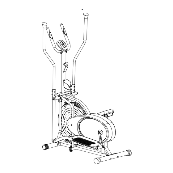
Page 7: Overview Drawing
OVERVIEW DRAWING... -
Page 8: Parts List
PARTS LIST Description Description 001 Handrail Arm End Cap Ø25 023 Bolt M8x43 Right Handrail Arm 024 Washer Ø8 Ø25x1.8x990 Handrail Arm Foam Grip 025 Nylon Nut M8 Ø24xØ34x280 Handrail Arm Plastic Bushing 026 Right Crank 6.7" Ø32x1.5 005 Bolt M10x18 027 Spring Washer Ø20xØ13x2 006 Spring Washer Ø10xØ18x3 028 Nylon Nut for Right Crank 1/2”... - Page 9 PARTS LIST Description Description 046 Tension Bracket 074 Nut 7/8" 047 Bolt M8x38 075 Left Crank 6.7" 048 Nut M6 076 Left Foot Bar 049 Fan Wheel Ø503x85 077 Left Handrail Fan Wheel Axle 078 Sensor with Wire L=900 mm M10x1xL150xL25xL40 051 Spacer Ø16xØ10x20 079 Tension Cable L=1020 mm...
-
Page 10: Hardware & Tools Pack
HARDWARE & TOOLS PACK... - Page 11 THIS PAGE IS INTENTIONALLY LEFT BLANK...
-
Page 12: Assembly
ASSEMBLY Tools: Open-Ended Flat Wrench 1. Front/Rear Stabilizers and Adjustable Levelers Installation: Align the holes of the Front Stabilizer (54) to the bracket located at the front end of the Mainframe (59). Make sure the arrow sticker on the Front Stabilizer (54) is pointing up so that the Transport Wheels (93) are positioned toward the front and parallel to the floor. -
Page 13: Right Handrail
ASSEMBLY Tools: 6mm Allen Wrench & 6mm Allen Wrench with Phillips Screwdriver 2. Handrails, Foot Bars and Rotation Rod Installation: Position the Right Foot Bar (17) so that it angles downwards as shown above. Attach the Right Foot Bar (17) onto the brackets on the bottom end of the Right Handrail (9) with one Bolt (11) and one Nylon Nut (14). - Page 14 ASSEMBLY Tools: R for right bolt Important: 6mm Allen Installing right bolt into right Wrench crank can only be done by turning right (CLOCKWISE). Open-Ended Flat Wrench 8mm Allen Wrench 3. Foot Pedal Support Bracket and Right Crank Bolt Installation: Attach the Foot Pedal Support Bracket (18) onto the right side of the Right Foot Bar (17) using two Bolts (23), two Washers (24), and two Nylon Nuts (25).
- Page 15 ASSEMBLY Figure F. Note: Figure F shows the correct installation of the Right Crank Bolt (21). Keep the bolt perfectly straight when the bolt goes through the Right Foot Bar (17), and is being screwed into the Right Crank (26). If the bolt is screwed into the crank at an angle, this may damage the equipment.
- Page 16 ASSEMBLY Tools: L for left bolt 6mm Allen Wrench Important: Installing left bolt into left crank can only be done by turning left (COUNTER-CLOCKWISE). Open-Ended Flat Wrench 8mm Allen Wrench 4. Foot Pedal Support Bracket and Left Crank Bolt Installation: Attach the Foot Pedal Support Bracket (18) onto the left side of the Left Foot Bar (76) using two Bolts (23), two Washers (24), and two Nylon Nuts (25).
- Page 17 ASSEMBLY Figure F. Note: Figure F shows the correct installation of the Left Crank Bolt (64). Keep the bolt perfectly straight when the bolt goes through the Left Foot Bar (76), and is being screwed into the Left Crank (75). If the bolt is screwed into the crank at an angle, this may damage the equipment.
- Page 18 ASSEMBLY Tools: Open-Ended Flat Wrench 5. Right and Left Foot Pedals Installation: Attach the Right Foot Pedal (19R) onto the top of the right side Foot Pedal Support Bracket (18) located on the Right Foot Bar (17) with two Bolts (20) and two Nylon Nuts (14). Tighten the Nylon Nuts (14) using the Open-Ended Flat Wrench provided.
- Page 19 ASSEMBLY Tools: 6mm Allen Wrench Open-Ended Flat Wrench 6. Right and Left Handrail Arms Installation: Insert the Right Handrail Arm (2) with the handlebar grip bent outwards into the Right Lower Handrail (9) and align the holes. Secure the Right Handrail Arm (2) using two Big Curve Washers (81), two Bolts (47), and two Cap Nuts (80).
- Page 20 ASSEMBLY Figure G Figure A Tools: 6mm Allen Wrench with Multi Hex Tool with Phillips Phillips Screwdriver Screwdriver 7. Support Frame Handlebar Installation: As you begin to mount the Hand Pulse Handlebar Support Frame (41) to the Mainframe (59), insert the Tension Cable (79) through the bottom opening in the shaft of the Hand Pulse Handlebar Support Frame (41) and pull it out through the shaft opening located midway up the support frame.
- Page 21 ASSEMBLY 8. Bottle holder and Tension Control Knob Installation: First turn the Tension Control Knob (37) to the lowest setting (counterclockwise). Hook the end of the resistance cable connected to the Tension Control Knob (37) to the Tension Cable (79), See Figure B.
- Page 22 ASSEMBLY Tools: Open-Ended Flat Wrench 9. Hand Pulse Handlebar Installation: Mount the Hand Pulse Handlebar (33) onto the top support bracket of the Hand Pulse Handlebar Support Frame (41) with two Carriage Bolts (39), two Cap Nuts (80), and two Big Curve Washers (81).
-
Page 23: Hand Pulse Sensor
ASSEMBLY Tools: Open-Ended Flat Wrench 10. Computer Console Installation: Connect the Extension Sensor Wire (10) coming out from the top side of the Hand Pulse Handlebar Support Frame (41) to the wire with a male connector coming out from under the Computer Console (29). -
Page 24: Computer Console
COMPUTER SPECIFICATIONS: TIME ---------------------------------------------------- 00:00-99:59 MIN: SEC SPEED ------------------------------------------------- 0.0-999.9 DISTANCE -------------------------------------------- 0.00-99.99 MILE CALORIE ---------------------------------------------- 0.0-999.9 KCAL PULSE ------------------------------------------------- 40-200 USING YOUR COMPUTER CONSOLE The computer console can be activated by pressing the MODE button or by pedaling. If you leave the equipment idle for 4 minutes, the power will turn off automatically. -
Page 25: Tension Adjustment
TENSION ADJUSTMENT Adjusting the Tension Control Knob Figure F To increase the tension, turn the tension control knob in a clockwise direction. To decrease the tension, turn the tension control knob in a counter-clockwise direction NOTE: After prolong use of the equipment, the strap will begin to stretch out and it will become necessary to tighten the strap for optimum performance. -
Page 26: Level Adjustments
LEVEL ADJUSTMENTS Adjusting the Rear Stabilizer End Cap The elliptical equipment has to be set up on a flat surface. Otherwise, shaking or wobble might occur during the workout. Please use the following two methods to adjust the elliptical equipment Level. IMPORTANT: Follow these steps to ensure the stability of the elliptical equipment while Figure G... -
Page 27: Moving The Elliptical Equipment
MOVING THE ELLIPTICAL EQUIPMENT TENSION ADJUSTMENTS Transporting the elliptical equipment Hold the Handlebar (33) and slowly lean the machine towards you until the wheels on the Front Stabilizer (93) make contact with the floor. Push or pull the unit to the desired location while balancing on the wheels. -
Page 28: Maintenance
MAINTENANCE Regular maintenance of your equipment is necessary to extend the life and will allow it to continue to function properly. Please keep the elliptical equipment, especially the computer console, out of direct sunlight to prevent screen damage or premature wear. Cleaning Keep the machine clean and free of any debris by vacuuming around the moving parts and wiping the machine down with a clean cotton cloth. -
Page 29: Troubleshooting
TROUBLESHOOTING PROBLEM SOLUTION The computer console will not Check that the batteries are inserted power up. properly with the correct polarity (see markings on the inside of the battery compartment). Check that the battery springs are in proper contact with batteries. Remove the old batteries and replace with the new batteries. - Page 30 TROUBLESHOOTING PROBLEM SOLUTION 1. Make sure both the Adjustable Levelers (57) are The elliptical equipment is not sturdy enough. touching the ground. 2. Make sure the elliptical equipment is leveled. Please refer to page 24. The tension adjustment doesn't 1. Undo the buckle of the Clip (101) and then pull the top work.
-
Page 31: Warranty
WARRANTY MANUFACTURER’S LIMITED WARRANTY Paradigm Health & Wellness warrants to the original purchaser that this product is free from defects in material and workmanship when used for the purpose intended, under the conditions that it has been installed and operated in accordance with Paradigm’s Owner’s Manual. -
Page 32: Parts Request Form
PARTS REQUEST FORM Paradigm Health & Wellness, Inc. EMAIL THIS FORM WITH YOUR RECEIPT OF PURCHASE TO Service@paradigmhw.com NAME: _______________________________________________________ ADDRESS: ____________________________________________________ CITY ______________ STATE ______________ ZIP ___________________ TELEPHONE: (Day) _____________________________________________ (Night) ____________________________________________ SERIAL#: _____________________________________________________ MODEL#: _____________________________________________________ PURCHASE DATE: _____________________________________________ PLACE OF PURCHASE: _________________________________________ PART # DESCRIPTION...
Need help?
Do you have a question about the 300LS and is the answer not in the manual?
Questions and answers