Table of Contents
Advertisement
Quick Links
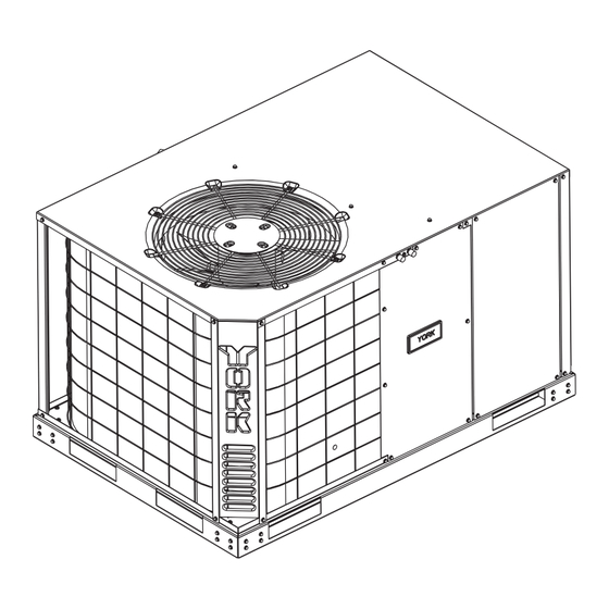
R-22, 13 SEER
LATITUDE™ SERIES
JP024-060
General . . . . . . . . . . . . . . . . . . . . . . . . . . . . . . . . . . . . . . . . . . 1
Installation . . . . . . . . . . . . . . . . . . . . . . . . . . . . . . . . . . . . . . . . 2
Limitations . . . . . . . . . . . . . . . . . . . . . . . . . . . . . . . . . . . . . . 2
Unit Location . . . . . . . . . . . . . . . . . . . . . . . . . . . . . . . . . . . . 3
Site Preparation . . . . . . . . . . . . . . . . . . . . . . . . . . . . . . . . . 4
Clearances . . . . . . . . . . . . . . . . . . . . . . . . . . . . . . . . . . . . . 4
(Manufactured Housing) . . . . . . . . . . . . . . . . . . . . . . . . . . . . . 6
Supply and Return Ducts . . . . . . . . . . . . . . . . . . . . . . . . . . 6
The Return - Air Grille Boxes . . . . . . . . . . . . . . . . . . . . . . 6
Wye Insulation. . . . . . . . . . . . . . . . . . . . . . . . . . . . . . . . . . . 7
Discharge Duct Installation . . . . . . . . . . . . . . . . . . . . . . . . . 8
Installing Of Duct To Unit (Residential) . . . . . . . . . . . . . . . . . . 9
Installing Drain Tube And Connection . . . . . . . . . . . . . . . . . . . 9
1 Unit Limitations . . . . . . . . . . . . . . . . . . . . . . . . . . . . . . . . . 3
2 Unit Dimensions . . . . . . . . . . . . . . . . . . . . . . . . . . . . . . . . 5
3 Unit Clearances . . . . . . . . . . . . . . . . . . . . . . . . . . . . . . . . . 6
4 Demand Defrost Selection . . . . . . . . . . . . . . . . . . . . . . . 12
5 Electrical Data . . . . . . . . . . . . . . . . . . . . . . . . . . . . . . . . . 13
6 Physical Data . . . . . . . . . . . . . . . . . . . . . . . . . . . . . . . . . 14
1 Component Location . . . . . . . . . . . . . . . . . . . . . . . . . . . . 3
2 Air Discharge Clearance . . . . . . . . . . . . . . . . . . . . . . . . . 4
3 Unit 4 Point Load Weight . . . . . . . . . . . . . . . . . . . . . . . . . 4
4 Unit Dimensions . . . . . . . . . . . . . . . . . . . . . . . . . . . . . . . . 5
5 Return Air Box and Grille . . . . . . . . . . . . . . . . . . . . . . . . . 6
6 Wye Installation (Outlet) . . . . . . . . . . . . . . . . . . . . . . . . . . 7
7 Wye Installation (Inlet and Outlet) . . . . . . . . . . . . . . . . . . 8
General
®
YORK
Model JP units are factory assembled heat pump
designed to be installed along side the home or building. Field-
installed electric heater accessories are available to provide
supplemental electric heat.
The units are completely assembled on rigid base rails. All
piping, refrigerant charge, and electrical wiring is factory
installed and tested. The units require only electric power and
duct connections at the point of installation.
The electric heaters have nickel-chrome resistance wire
elements and utilize single point power connection.
Safety Considerations
This is a safety alert symbol
labels or in manuals, be alert to the potential for personal injury.
Understand and pay particular attention to the signal words
DANGER, WARNING or CAUTION.
TABLE OF CONTENTS
LIST OF TABLES
LIST OF FIGURES
. When you see this symbol on
Service Access . . . . . . . . . . . . . . . . . . . . . . . . . . . . . . . . . . 9
Power And Control Wiring . . . . . . . . . . . . . . . . . . . . . . . . . . . . 9
Power Wiring. . . . . . . . . . . . . . . . . . . . . . . . . . . . . . . . . . . . 9
Control Wiring . . . . . . . . . . . . . . . . . . . . . . . . . . . . . . . . . . 10
Wall Thermostat Installation . . . . . . . . . . . . . . . . . . . . . . . . . 10
Pre-start Procedure . . . . . . . . . . . . . . . . . . . . . . . . . . . . . . . . 11
System Startup, Check-out . . . . . . . . . . . . . . . . . . . . . . . . . . 11
Other Features Incorporated In The Control . . . . . . . . . . . . . 11
Anti-Short Cycle Time Delay . . . . . . . . . . . . . . . . . . . . . . . 11
Safety Lock-Out . . . . . . . . . . . . . . . . . . . . . . . . . . . . . . . . 11
Airflow Performance . . . . . . . . . . . . . . . . . . . . . . . . . . . . . . . 15
Maintenance . . . . . . . . . . . . . . . . . . . . . . . . . . . . . . . . . . . . . 17
Normal Maintenance . . . . . . . . . . . . . . . . . . . . . . . . . . . . . 17
Typical Wiring Diagrams . . . . . . . . . . . . . . . . . . . . . . . . . . 18
7 Airflow Performance . . . . . . . . . . . . . . . . . . . . . . . . . . . . 15
8 Additional Static Resistance . . . . . . . . . . . . . . . . . . . . . . 15
9 Electric Heat Minimum Supply Air . . . . . . . . . . . . . . . . . 17
10 Indoor Blower Specifications . . . . . . . . . . . . . . . . . . . . . . 17
11 Electric Heat Multipliers . . . . . . . . . . . . . . . . . . . . . . . . . 17
8 Duct Connector (With Damper) . . . . . . . . . . . . . . . . . . . . 8
9 Duct Connector (No Damper) . . . . . . . . . . . . . . . . . . . . . 8
10 Unit Component Location . . . . . . . . . . . . . . . . . . . . . . . 10
11 Thermostat Wiring . . . . . . . . . . . . . . . . . . . . . . . . . . . . . 10
12 Switch Installation . . . . . . . . . . . . . . . . . . . . . . . . . . . . . 11
13 Defrost Operation Curves . . . . . . . . . . . . . . . . . . . . . . . 12
14 Demand Defrost "Curve" Selection Jumper . . . . . . . . . . 12
DANGER indicates an imminently hazardous situation, which,
if not avoided, will result in death or serious injury.
WARNING indicates a potentially hazardous situation, which,
if not avoided, could result in death or serious injury.
CAUTION indicates a potentially hazardous situation, which, if
not avoided may result in minor or moderate injury. It is also
used to alert against unsafe practices and hazards involving
only property damage.
Improper installation may create a condition where the
operation of the product could cause personal injury or
property damage. Improper installation, adjustment,
alteration, service or maintenance can cause injury or
property damage. Refer to this manual for assistance or
for additional information, consult a qualified contractor,
installer or service agency.
SO 9001
Certified Quality
Management System
161036-YIM-E-1008
Advertisement
Table of Contents

Subscribe to Our Youtube Channel
Related Manuals for York LATITUDE JP024-060


Summary of Contents for York LATITUDE JP024-060
-
Page 1: Table Of Contents
DANGER indicates an imminently hazardous situation, which, if not avoided, will result in death or serious injury. ® YORK Model JP units are factory assembled heat pump WARNING indicates a potentially hazardous situation, which, designed to be installed along side the home or building. Field- if not avoided, could result in death or serious injury. -
Page 2: Installation
Renewal Parts could cause personal injury. Improper installation, ® adjustment, alteration, service or maintenance can Contact your local York parts distribution center for authorized cause injury or property damage. Refer to this manual. replacement parts. For assistance or additional information consult a qualified installer or service agency. -
Page 3: Unit Location
161036-YIM-E-1008 If components are to be added to a unit to meet local codes, Size of unit for proposed installation should be based on heat they are to be installed at the dealer's and/or the customer's loss/heat gain calculations made in accordance with industry expense. -
Page 4: Site Preparation
161036-YIM-E-1008 Proximity to the clothes dryer vent – The clothes dryer vent by concrete pads. The heat pump must set level and should not be located upwind from the unit. securely upon the support. Ability to service – Side access panels of the unit should NOTE: If installing on blocks, the middle rail must be supported. -
Page 5: Unit Dimensions
161036-YIM-E-1008 HIGH VOLTAGE CONN. Ø7/8" KNOCKOUT HIGH VOLTAGE CONN. Ø1 3/32" KNOCKOUT HIGH VOLTAGE CONN. Ø1 3/8" 15-13/16 KNOCKOUT 13-9/16 CONDENSATE DRAIN 3/4" NPT LOW VOLTAGE CONN. Ø7/8" BUSHING 7-7/16 4-13/16 4-3/8 DUCT FLANGE ØG 1-15/16 2-9/16 Unit Dimensions Figure 4: Table 2: Unit Dimensions Size Dimensions... -
Page 6: Installing Of Duct To Unit (Manufactured Housing)
161036-YIM-E-1008 Table 3: Unit Clearances Distance Distance Direction Direction (in.) (in.) Right Front Left Rear Bottom 1. Units must be installed outdoors. Over hanging structure or shrubs should not obscure condenser air discharge outlet. 2. Unit may be positioned to draw air from underneath structure. Installing Of Duct To Unit must be covered with a vapor barrier. -
Page 7: Wye Insulation
161036-YIM-E-1008 When attaching the flex duct to the return air box, secure Insert a stub collar in the raw end of the duct and tape the duct collar and return box collar together with at least securely in place. three (3) sheet metal screws and seal with duct tape. Make sure the duct is not stretched tight and does not have Set the return air box, with flex duct attached, back into the kinks from excessive length after installation. -
Page 8: Discharge Duct Installation
161036-YIM-E-1008 Grille Filter Return Box Damper* Flex Duct Grille 12” Duct Connectors Filter Return Box Damper* Flex Duct Flex Duct WYE Insulation Recommended 12 x12 x12 12 x12 x12 for Greater Efficiency and Performance of Unit. May use duct connector without damper if no interior furnace or air handler is connected to duct system. -
Page 9: Installing Of Duct To Unit (Residential)
161036-YIM-E-1008 Service Access If using the duct connector with damper, cut a 9-1/8”x 16-1/8” hole in the center of the duct bottom. If using the 12” diameter Access to all serviceable components is provided at the duct connector without damper cut a 12-1/8” diameter hole in following locations: the center of the duct bottom. -
Page 10: Control Wiring
161036-YIM-E-1008 For single phase units - Connect one supply wire to L1 on W1 or 66 the contactor, and the other supply wire to L2 on the contactor. Connect ground wire to ground lug in control box. See Figure 10. PKG. -
Page 11: Pre-Start Procedure
161036-YIM-E-1008 Never locate it in a room that is warmer or cooler than the Set the wall thermostat system switch to the HEAT rest of the home, such as a kitchen or hallway. position. The heat pump should stop. The living or dining room is normally a good location Raise the wall thermostat temperature selection lever to a provided there is no cooking range or refrigerator on the setting above the room temperature. -
Page 12: Demand Defrost Selection
161036-YIM-E-1008 Defrost Operation inhibit feature prohibits defrost if the coil temperature is above 40°F. The demand defrost control implements a temperature differential (”delta-T”) demand defrost algorithm. The heat pump A forced-defrost feature puts the system into a defrost period is allowed to operate in the heating mode until the combination every 6 hours and 4 minutes to recirculate lubricants, unless the of outdoor ambient and outdoor coil temperatures indicate that coil temperature is above 40°F. -
Page 13: Ton
161036-YIM-E-1008 Table 5: Electrical Data OD Fan Supply Max Fuse Compressors Motors Blower Electric Heat Option Size Breaker (each) Volt (each) Motor (Tons) (Amps) Size (Amps) Model Stages Amps None 18.0 2PH08510506 3.6/4.8 17.2/19.9 39.5/42.8 45/45 208/230-1-60 10.2 53.5 16.0 2PH08510706 4.9/6.5 23.5/27.1... -
Page 14: Physical Data
161036-YIM-E-1008 Table 6: Physical Data Models Component JP024 JP030 JP036 JP042 JP048 JP060 Nominal Tonnage ARI COOLING PERFORMANCE Gross Capacity @ ARI A point (Btu) 25160 29700 37000 45800 50600 55700 ARI net capacity (Btu) 24660 29000 36000 44700 49300 53600 11.95 11.5... -
Page 15: Airflow Performance
161036-YIM-E-1008 Airflow Performance Table 7: Airflow Performance External Static Pressure (Inch Water Gauge) Size Unit Speed) (Tons) SCFM SCFM SCFM SCFM SCFM 1074 Low/Medium 1004 1115 Medium 1005 1072 (2.0) Medium/High 1185 1137 1071 1048 1010 1109 1170 High 1336 1031 1263 1081... - Page 16 161036-YIM-E-1008 Table 8: Additional Static Resistance (Continued) Electric Heat, kW Size Model Wet Indoor Coil (Tons) 0.09 0.09 0.09 0.10 0.12 0.10 0.10 0.11 0.13 0.12 0.12 0.12 0.13 0.15 0.13 0.13 0.13 0.14 0.17 0.15 0.15 0.15 0.16 0.19 1000 0.17 0.17...
-
Page 17: Maintenance
161036-YIM-E-1008 Table 9: Electric Heat Minimum Supply Air Minimum Supply Air (CFM) Size Voltage Heater kW (Tons) 10.0 15.0 208/230-1-60 (2.0) 208/230-1-60 (2.5) 208/230-1-60 (3.0) 208/230-1-60 1300 1300 1270 1270 (3.5) 208/230-1-60 1300 1300 1270 1270 (4.0) 208/230-1-60 1300 1300 1270 1270 (5.0) -
Page 18: Typical Wiring Diagrams
161036-YIM-E-1008 Typical Wiring Diagrams JP024-060 Typical Heat Pump 208/230-1-60 volt Wiring Diagram Johnson Controls Unitary Products... - Page 19 161036-YIM-E-1008 JP036, 048 and 060 Typical Heat Pump 208/230-3-60 volt Wiring Diagram Johnson Controls Unitary Products...
- Page 20 JP060 Typical Heat Pump 460-3-60 volt Wiring Diagram Subject to change without notice. Printed in U.S.A. 161036-YIM-E-1008 Copyright © 2008 by Johnson Controls, Inc. All rights reserved. Supersedes: 161036-YIM-D-1206 Johnson Controls Unitary Products 5005 York Drive Norman, OK 73069...
Need help?
Do you have a question about the LATITUDE JP024-060 and is the answer not in the manual?
Questions and answers