Table of Contents
Advertisement
Advertisement
Table of Contents

Related Manuals for ZyXEL Communications GS1200-5HP v2


Summary of Contents for ZyXEL Communications GS1200-5HP v2
- Page 1 User’s Guide GS1200 Series GS1200-5/GS1200-5HP v2/GS1200-8/GS1200-8HP v2 5-Port / 8-Port Web Managed (PoE) Gigabit Switch Default Login Details Version 1.00 Edition 1, 12/2017 LAN IP Address http://192.168.1.3 Password 1234 Copyright © 2017 Zyxel Communications Corporation...
-
Page 2: Related Documentation
IMPORTANT! READ CAREFULLY BEFORE USE. KEEP THIS GUIDE FOR FUTURE REFERENCE. This is a User’s Guide for a series of products. Not all products support all firmware features. Screenshots and graphics in this book may differ slightly from your product due to differences in your product firmware or your computer operating system. -
Page 3: Document Conventions
Syntax Conventions • The GS1200-5, GS1200-5HP v2, GS1200-8, and GS1200-8HP v2 may be referred to as the “Switch” in this guide. • Product labels, screen names, field labels and field choices are all in bold font. -
Page 4: Table Of Contents
Contents Overview Contents Overview User’s Guide ............................1 Getting to Know Your Switch ........................ 1 Hardware Installation ..........................1 Hardware Panels ............................ 2 The Web Configurator ........................... 1 Initial Setup Example ..........................6 Technical Reference ..........................1 System ..............................1 Port ................................4 VLAN ................................ - Page 5 Table of Contents Table of Contents Document Conventions ........................1 Contents Overview ..........................1 Table of Contents ..........................1 Part I: User’s Guide.................... 1 Chapter 1 Getting to Know Your Switch ......................1 1.1 Introduction ............................1 1.2 Applications ............................2 1.2.1 Bridging Application ....................... 2 1.2.2 VLAN Application Example ....................
-
Page 6: Table Of Contents
Table of Contents Chapter 5 Initial Setup Example ...........................6 5.1 Overview ............................6 5.1.1 Creating a VLAN ........................6 5.1.2 Setting Port VID ........................8 5.1.3 Power over Ethernet (PoE) Configuration ................9 Part II: Technical Reference................1 Chapter 6 System..............................1 6.1 Overview ............................ - Page 7 Table of Contents 11.2.2 IEEE 802.1p QoS ........................15 11.2.3 Weighted Round Robin Scheduling (WRR) ..............16 11.3 Port-Based QoS Screen ........................ 17 11.4 IEEE 802.1P QoS Screen ........................ 18 Chapter 12 IGMP Snooping ..........................19 12.1 Overview ............................19 12.2 IGMP Snooping Screen ........................ 19 Chapter 13 Management .............................21 13.1 Overview ............................
-
Page 8: User's Guide
User’s Guide... -
Page 9: Getting To Know Your Switch
IP cameras, print servers to your home network. The PoE ports of the GS1200-5HP v2 and GS1200-8HP v2 support IEEE802.3at High Power over Ethernet (PoE) and IEEE802.3af PoE standard, to provide power to IP CAM, wall mounted AP, and other devices that may be far from a power outlet. -
Page 10: Applications
Chapter 1 Getting to Know Your Switch Table 1 GS1200 Series Comparison Table MODEL GS1200-5 GS1200-5HP V2 GS1200-8 GS1200-8HP V2 IGMP Snooping v1/v2 and v3 Compatible Broadcast Storm Control Firmware Upgrade Configuration Restore and Backup 1.2 Applications This section shows a few examples of using the Switch in various network environments. -
Page 11: Ways To Manage The Switch
Chapter 1 Getting to Know Your Switch Shared resources such as a server can be used by all ports in the same VLAN as the server. In the following figure only ports that need access to the server need to be part of VLAN1. Ports can belong to other VLAN groups too. -
Page 12: Hardware Installation
H A P T E R Hardware Installation 1.1 Installation Scenarios This chapter shows you how to install and connect the Switch. The Switch can be placed on a desktop. Use the rubber feet in a desktop installation. 1.2 Desktop Installation Procedure Make sure the Switch is clean and dry. -
Page 13: Hardware Panels
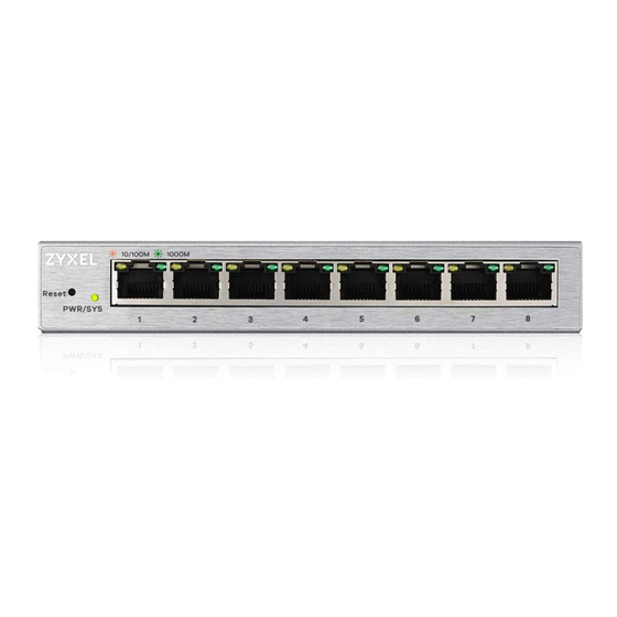
2.1 Front Panel The following figures show the front panels of the Switch. Figure 1 Front Panel: GS1200-5 Figure 2 Front Panel: GS1200-5HP v2 Figure 3 Front Panel: GS1200-8 Figure 4 Front Panel: GS1200-8HP v2 2.2 Rear Panel The following figures show the rear panels of the Switch. -
Page 14: Power Connector
Chapter 2 Hardware Panels Figure 6 Rear Panel: GS1200-5HP v2 Figure 7 Rear Panel: GS1200-8 Figure 8 Rear Panel: GS1200-8HP v2 2.2.1 Power Connector Note: Make sure you are using the correct power source as shown on the panel. To connect power to the Switch, insert the female end of the power cord to the AC power receptacle on the rear panel. -
Page 15: Leds
Chapter 2 Hardware Panels 2.3 LEDs After you connect the power to the Switch, view the LEDs to ensure proper functioning of the Switch and as an aid in troubleshooting. Table 1 LED Descriptions COLOR STATUS DESCRIPTION PWR/SYS Green The system power is on. Blinking The system is starting up. -
Page 16: The Web Configurator
H A P T E R The Web Configurator 1.1 Overview This section introduces the configuration and functions of the web configurator. The web configurator is an HTML-based management interface that allows easy Switch setup and management via Internet browser. Use Internet Explorer 10.0 and later versions, Mozilla Firefox 46.0.1 and later versions, or Google Chrome 50.0 and later versions. -
Page 17: The Web Configurator Layout
The System screen is the first screen that displays when you access the web configurator. This guide uses GS1200-5HP v2 screens as an example. The screens may vary slightly for different models. The following figure shows the navigating components of a web configurator screen. - Page 18 Chapter 1 The Web Configurator Figure 3 Web Configurator Layout A - Click the menu items to open the screen in the main window. B - Click this link to log out of the web configurator. The following table describes the links in the navigation panel. Table 1 Navigation Panel Links LINK DESCRIPTION...
-
Page 19: Change Your Password
Chapter 1 The Web Configurator Table 1 Navigation Panel Links (continued) LINK DESCRIPTION IGMP Snooping This link takes you to a screen where you can configure IGMP snooping. Management This link takes you to screens where you can change the system login password, perform firmware upgrade and configuration file maintenance as well as reboot the system. -
Page 20: Resetting The Switch
Chapter 1 The Web Configurator You forgot to log out of the Switch from a computer before logging in again on another computer. Note: Be careful not to lock yourself and others out of the Switch. 1.5 Resetting the Switch If you forget the administrator password or cannot access the Web Configurator, you will need to use the Reset button at the front panel of the device to reset the Switch back to the factory defaults. -
Page 21: Initial Setup Example
H A P T E R Initial Setup Example 2.1 Overview This chapter shows how to set up the Switch for an example network. The following lists the configuration steps for the initial setup: • Creating a VLAN • Setting Port VID •... - Page 22 Chapter 2 Initial Setup Example Enter 2 in the VLAN ID field for the VLAN2 network. Since the VLAN2 network is connected to port 1 on the Switch, configure port 1 to be a permanent member of the VLAN. To ensure that VLAN-unaware devices (such as computers and hubs) can receive frames properly, set the port’s box color to green to set the Switch to remove VLAN tags before sending.
-
Page 23: Setting Port Vid
Chapter 2 Initial Setup Example 2.1.2 Setting Port VID Use PVID to add a tag to incoming untagged frames received on that port so that the frames are forwarded to the VLAN group that the tag defines. In the example network, configure 2 as the port VID on port 1 so that any untagged frames received on that port get sent to VLAN 2. -
Page 24: Power Over Ethernet (Poe) Configuration
Chapter 2 Initial Setup Example 2.1.3 Power over Ethernet (PoE) Configuration This example is for GS1200-5HP v2 and GS1200-8HP v2. Figure 21 on page 5 for an example of using PoE to power devices. Before connecting devices that require PoE to the PoE ports, PD (Powered Devices), you must enable PoE on those ports. - Page 25 Chapter 2 Initial Setup Example GS1200 Series User’s Guide...
-
Page 26: Technical Reference
Technical Reference... -
Page 27: System
H A P T E R System 1.1 Overview This chapter describes the screens for system status, and port details. 1.2 System Screen The System screen displays when you log into the Switch or click System at the top of the web configurator. - Page 28 PoE Total Power This field displays the total power the Switch can provide to the connected PoE-enabled devices on the PoE ports. (GS1200-5HP v2 & GS1200-8HP PoE Total Power This field displays the amount of power the Switch can still provide for PoE.
- Page 29 This field displays the point when the PoE MAX LED will turn on, indicating the Switch is reaching Power its maximum power. (GS1200-5HP v2 When the total power requested by the PoE-enabled devices exceeds the total PoE power & GS1200-8HP budget on the Switch, the last PoE-enabled device connected to the Switch won’t be powered...
-
Page 30: Port
H A P T E R Port 2.1 Overview This chapter introduces and shows you how to configure the broadcast storm control feature and use loop prevention or loop detection to prevent loops in your network. In addition, you can configure transmission speed, flow control, and PoE on a port. -
Page 31: Port Screen
Enable this feature to reduce broadcast packets in your network. You can specify limits on each port. 2.1.1.3 PoE (GS1200-5HP v2 & GS1200-8HP v2) The Switch supports both the IEEE 802.3af Power over Ethernet (PoE) and IEEE 802.3at High Power over Ethernet (PoE) standards. - Page 32 Chapter 2 Port Figure 6 Port The following table describes the labels in this screen. Table 2 Port LABEL DESCRIPTION Storm Control Broadcast Storm Enable traffic storm control on the Switch by specifying how many broadcast packets a port Control receives per second.
- Page 33 Select the check box to enable it. Select Enable to provide power to a PoE-enabled device connected to the port or Disable so the port cannot receive power from the Switch. (GS1200-5HP v2 & GS1200-8HP v2) Apply Click this button to save your changes to the Switch.
-
Page 34: Vlan
H A P T E R VLAN 3.1 Overview This chapter shows you how to configure VLAN settings. 3.1.1 What You Need to Know Read this section to know more about VLAN and how to configure the screens. 3.1.1.1 IEEE 802.1Q Tagged VLANs A tagged VLAN uses an explicit tag (VLAN ID) in the MAC header to identify the VLAN membership of a frame across bridges - they are not confined to the switch on which they were created. -
Page 35: Vlan Screen
Chapter 3 VLAN 3.2 VLAN Screen Use this screen to view and configure VLAN settings for the Switch. Click VLAN in the navigation panel to open the following screen. Note: You could block yourself (and all others) from managing the Switch if you remove all ports from the management VLAN (VLAN 1 by default). - Page 36 Chapter 3 VLAN Table 3 VLAN (continued) LABEL DESCRIPTION VLAN ID This is the ID number of the VLAN group. Enter a number between 1 and 4094 as the VLAN ID. 01 ~ 08 This displays the ports that are participating in a VLAN. A tagged port is orange, an untagged port is green and ports not participating in a VLAN are gray.
-
Page 37: Link Aggregation
H A P T E R Link Aggregation 4.1 Overview This chapter shows you how to logically aggregate physical links to form one logical and higher bandwidth link. Link aggregation is the grouping of physical ports into one logical higher-capacity link. You may want to trunk ports if for example, it is cheaper to use multiple lower-speed links than to under-utilize a high- speed, but more costly, single-port link. - Page 38 The field identifies the default link aggregation group(s) the Switch supports. Group Note: By default, the GS1200-5 and GS1200-5HP v2 have a link aggregation group containing ports 3 and 4. Note: By default, the GS1200-8 and GS1200-8HP v2 have two link aggregation groups.
-
Page 39: Mirroring
H A P T E R Mirroring 5.1 Overview This chapter discusses port mirroring setup screens. Port mirroring allows you to copy a traffic flow to a monitor port (the port you copy the traffic to) in order that you can examine the traffic from the monitor port without interference. 5.2 Mirroring Screen Use this screen to select a monitor port and specify the traffic flow to be copied to the monitor port. - Page 40 Chapter 5 Mirroring Table 5 Mirroring (continued) LABEL DESCRIPTION Port This field displays the port number. Monitor Port The monitor port is the port you copy the traffic to in order to examine it in more detail without interfering with the traffic flow on the original port(s). Note: Select one monitor port.
-
Page 41: Qos
H A P T E R 6.1 Overview This chapter introduces the configuration and functions of the QoS (Quality of Service) screen. The QoS (Quality of Service) feature allows you to prioritize the flow of data passing through the Switch. Occasionally, data might be delayed, depending on the volume of traffic and the capacity of the equipment. -
Page 42: Weighted Round Robin Scheduling (Wrr)
Chapter 6 QoS class of service. The table below shows the IEEE recommendations for traffic types, these may vary or be reassigned. Table 6 IEEE Priority to Traffic Type Mapping Recommendations PRIORITY ACRONYM TRAFFIC TYPES 0 (lowest) Background 1 (default) Best Effort Excellent Effort Critical Applications... -
Page 43: Port-Based Qos Screen
Chapter 6 QoS 6.3 Port-Based QoS Screen The Switch’s default settings for Port-Based QoS are shown in the next figure. Figure 12 QoS > Port-Based QoS The Switch allows four priority levels, shown in the table below. Table 7 Priority Queuing Levels in QoS QUEUE NAME PRIORITY LEVEL Queue 0... -
Page 44: Ieee 802.1P Qos Screen
Chapter 6 QoS 6.4 IEEE 802.1P QoS Screen Both Port-Based QoS and IEEE 802.1P QoS use the same priority queuing levels, shown in Table 10 on page 17. Remember the difference amongst both features relies on how the priority queuing is assigned. -
Page 45: Igmp Snooping
IGMP versions 1, 2 and 3 respectively. Note: You must enable IGMP snooping to use the IPTV service. The following table introduces the IGMP snooping default settings of the Switch. Table 8 IGMP Snooping Default Settings GS1200-5 GS1200-5HP V2 GS1200-8 GS1200-8HP V2 Enable IGMP Static Router... - Page 46 Chapter 7 IGMP Snooping Figure 14 IGMP Snooping The following table describes the labels in this screen. Table 9 IGMP Snooping LABEL DESCRIPTION IGMP Snooping Enable IGMP Select this option to enable IGMP Snooping to forward group multicast traffic only to ports that Snooping are members of that group.
-
Page 47: Management
H A P T E R Management 8.1 Overview This chapter explains how to Use the Management screens to configure settings on the Switch, such as login password change, firmware upgrade, system reset or reboot, IP address change, and so on. 8.1.1 What You Need to Know Read this section to know more about IEEE 802.3az Energy Efficient Ethernet (EEE). - Page 48 Chapter 8 Management Figure 15 Switch Management The following table describes the labels in this screen. Table 10 Switch Management LABEL DESCRIPTION Device Setting Reset Click this button to clear all Switch configuration information you configured and return to the factory defaults.
-
Page 49: Firmware Upgrade Screen
Chapter 8 Management Table 10 Switch Management (continued) LABEL DESCRIPTION Gateway Type the IP address of the default outgoing gateway in dotted decimal notation, for example 192.168.1.254. Apply Click this button to save your changes to the Switch. IEEE 802.3az EEE Select Enable to activate Energy Efficient Ethernet globally, or select Disable. - Page 50 Chapter 8 Management If you click the Cancel button in the Firmware Upgrade page, the Switch will reboot, and you’ll be direct to the login screen. Figure 17 Firmware Upgrade Path GS1200 Series User’s Guide...
-
Page 51: Troubleshooting
H A P T E R Troubleshooting This chapter offers some suggestions to solve problems you might encounter. The potential problems are divided into the following categories. • Power, Hardware Connections, and LEDs • Switch Access and Login • Switch Configuration 1.1 Power, Hardware Connections, and LEDs The Switch does not turn on. -
Page 52: Switch Access And Login
Chapter 1 Troubleshooting Check to see that the power adaptor is securely connected to the Switch. Check to see the Switch is connected to an appropriate power source, and make sure the power source is on and functioning properly. Check that the Ethernet cables connection to the devices requiring PoE are connected properly. Make sure you are using the correct type of Ethernet cable. - Page 53 Chapter 1 Troubleshooting I cannot see or access the Login screen in the web configurator. Make sure you are using the correct IP address. • The default IP address is 192.168.1.3. • If you changed the IP address, use the new IP address. •...
-
Page 54: Switch Configuration
Chapter 1 Troubleshooting 1.3 Switch Configuration After upgrading firmware on the Switch, the login screen doesn’t display. You will see the Firmware Upgrade screen, when one of the following situations happens. These will lead to a failure at upgrading firmware. During the firmware upgrade process: •... -
Page 55: Appendix A Customer Support
• Brief description of the problem and the steps you took to solve it. Corporate Headquarters (Worldwide) Taiwan • Zyxel Communications Corporation • http://www.zyxel.com Asia China • Zyxel Communications (Shanghai) Corp. Zyxel Communications (Beijing) Corp. Zyxel Communications (Tianjin) Corp. • http://www.zyxel.cn India • Zyxel Technology India Pvt Ltd • http://www.zyxel.in Kazakhstan •... - Page 56 • Zyxel Singapore Pte Ltd. • http://www.zyxel.com.sg Taiwan • Zyxel Communications Corporation • http://www.zyxel.com/tw/zh/ Thailand • Zyxel Thailand Co., Ltd • http://www.zyxel.co.th Vietnam • Zyxel Communications Corporation-Vietnam Office • http://www.zyxel.com/vn/vi Europe Austria • Zyxel Deutschland GmbH • http://www.zyxel.de Belarus • Zyxel BY • http://www.zyxel.by...
- Page 57 Appendix A Customer Support Belgium • Zyxel Communications B.V. • http://www.zyxel.com/be/nl/ • http://www.zyxel.com/be/fr/ Bulgaria • Zyxel България • http://www.zyxel.com/bg/bg/ Czech Republic • Zyxel Communications Czech s.r.o • http://www.zyxel.cz Denmark • Zyxel Communications A/S • http://www.zyxel.dk Estonia • Zyxel Estonia • http://www.zyxel.com/ee/et/ Finland •...
- Page 58 • Zyxel Communications Poland • http://www.zyxel.pl Romania • Zyxel Romania • http://www.zyxel.com/ro/ro Russia • Zyxel Russia • http://www.zyxel.ru Slovakia • Zyxel Communications Czech s.r.o. organizacna zlozka • http://www.zyxel.sk Spain • Zyxel Communications ES Ltd • http://www.zyxel.es Sweden • Zyxel Communications • http://www.zyxel.se Switzerland •...
- Page 59 Appendix A Customer Support • http://www.zyxel.ch/ Turkey • Zyxel Turkey A.S. • http://www.zyxel.com.tr • Zyxel Communications UK Ltd. • http://www.zyxel.co.uk Ukraine • Zyxel Ukraine • http://www.ua.zyxel.com Latin America Argentina • Zyxel Communication Corporation • http://www.zyxel.com/ec/es/ Brazil • Zyxel Communications Brasil Ltda.
-
Page 60: North America
Appendix A Customer Support North America • Zyxel Communications, Inc. - North America Headquarters • http://www.zyxel.com/us/en/ Oceania Australia • Zyxel Communications Corporation • http://www.zyxel.com/au/en/ Africa South Africa • Nology (Pty) Ltd. • http://www.zyxel.co.za GS1200 Series User’s Guide... -
Page 61: Appendix B Legal Information
The contents of this publication may not be reproduced in any part or as a whole, transcribed, stored in a retrieval system, translated into any language, or transmitted in any form or by any means, electronic, mechanical, magnetic, optical, chemical, photocopying, manual, or otherwise, without the prior written permission of Zyxel Communications Corporation. Published by Zyxel Communications Corporation. All rights reserved. -
Page 62: Appendix A Legal Information
Appendix A Legal Information List of national codes COUNTRY ISO 3166 2 LETTER CODE COUNTRY ISO 3166 2 LETTER CODE Austria Liechtenstein Belgium Lithuania Bulgaria Luxembourg Croatia Malta Cyprus Netherlands Czech Republic Norway Denmark Poland Estonia Portugal Finland Romania France Serbia Germany Slovakia... - Page 63 Appendix A Legal Information European Union - Disposal and Recycling Information The symbol below means that according to local regulations your product and/or its battery shall be disposed of separately from domestic waste. If this product is end of life, take it to a recycling station designated by local authorities. At the time of disposal, the separate collection of your product and/or its battery will help save natural resources and ensure that the environment is sustainable development.
-
Page 64: Zyxel Limited Warranty
North American products. Trademarks ZyNOS (Zyxel Network Operating System) and ZON (Zyxel One Network) are registered trademarks of Zyxel Communications, Inc. Other trademarks mentioned in this publication are used for identification purposes only and may be properties of their respective owners. -
Page 65: Index
Index Index airflow IGMP snooping applications initial setup backbone installation desktop installation scenarios certifications viewing LEDs CFI (Canonical Format Indicator) login changing the password password contact information login account Administrator copyright customer support managing the device good habits default IP disclaimer network applications front panel... - Page 66 Index rear panel connections registration product resetting restoring configuration status switch reset tagged VLAN trademarks number of possible VIDs priority frame VID (VLAN Identifier) VLAN introduction PVID tagged VLAN ID 8, 10 warranty note web configurator home login logout GS1200 Series User’s Guide...
Need help?
Do you have a question about the GS1200-5HP v2 and is the answer not in the manual?
Questions and answers