Table of Contents

Related Manuals for Carrier 42HWG009


Summary of Contents for Carrier 42HWG009
- Page 1 TECHNICAL DATA & SERVICE MANUAL SPLIT SYSTEM AIR CONDITIONER 42HWG-Series, 42HQG-Series, HWG ... H-Series, HWG ... C-Series INDOOR UNIT 42HWG007/009/012/018/024 42HQG007/009/012/018/024 HWG195C/225C/305C/455C/605C HWG195H/225H/305H/455H/605H...
-
Page 2: Table Of Contents
Contents 11. SPECIFICATIONS ........................2 12. OUTLINE AND DIMENSIONS .....................6 13. OPERATION ..........................7 14. WIRING DIAGRAM ........................29 15. REFRIGERANT CYCLE ......................33 16. CONTROL BLOCK DIAGRAM ....................35 17. ELECTRIC CIRCUIT DIAGRAM ....................37 18. KEY COMPONENTS OF ELECTRONIC CIRCUIT ..............50 19. CHECKING AND REPAIRING OF ELECTRIC PARTS .............. 55 10. -
Page 3: Specifications
SPECIFICATIONS Model 42HWG007/HWG195C 42HWG009/HWG225C 42HWG012/HWG305C Function Cooling Cooling Cooling Power Supply 230V-1PH-50Hz 230V-1PH-50Hz 230V-1PH-50Hz 2050 2410 3140 Capacity Btu/h 7000 8300 10700 Dehumidification Electrical data 0.11 0.11 0.16 (ID unit only) Electrical data (System) 1190 1200 1700 Indoor unit Indoor unit... - Page 4 Model 42HQG007/HWG195H-SERIES 42HQG009/HWG225H-SERIES 42HQG012/HWG305H-SERIES Function Cooling Heating Cooling Heating Cooling Heating Power Supply 220/240V-1PH-50Hz 220/240V-1PH-50Hz 220/240V-1PH-50Hz 2020 2150 2350 2740 3110 3250 Capacity 6900 7340 8020 9350 10600 11000 Btu/h Dehumidification Electrical data 0.11 0.11 0.16 (ID unit only) Electrical data 3.24 3.06 4.22...
- Page 5 42HWG018 / HWG455C Model 42HWG024 / HWG605C Cooling Function Cooling 230V-1PH-50Hz Power Supply 230V-1PH-50Hz 4690 6240 Capacity 16007 Btu/h 21300 0.19 Electrical data 0.19 (ID unit only) Electrical data 10.6 1780 (System) 2420 2270 3300 Cross flow fan Type Cross flow fan 1150/950 RPM (Hi/Lo) 1250/1050...
- Page 6 42HQG018 HWG455H Model 42HQG024 HWG605H Cooling Heating Function Cooling Heating 230V-1PH-50Hz Power Supply 230V-1PH-50Hz 4790 5100 6110 7170 Capacity 16360 17420 Btu/h 20886 24486 0.19 0.19 Electrical data 0.19 0.19 (ID unit only) Electrical data 10.7 1630 1490 (System) 2430 2480 17.0 14.6...
-
Page 7: Outline And Dimensions
OUTLINE AND DIMENSIONS INDOOR UNIT MAIN BODY MOUNTING PLATE POWER PLUG CONNECTION TUBE DRAIN HOSE MODEL 42HWG007/009 42HQG007/009 HWG195C/195H/225C/225H 42HWG012,42HQG012, HWG305C/305H 42HWG018/024, 42HQG018/024, 1080 HWG455C/455H/605C/605H... -
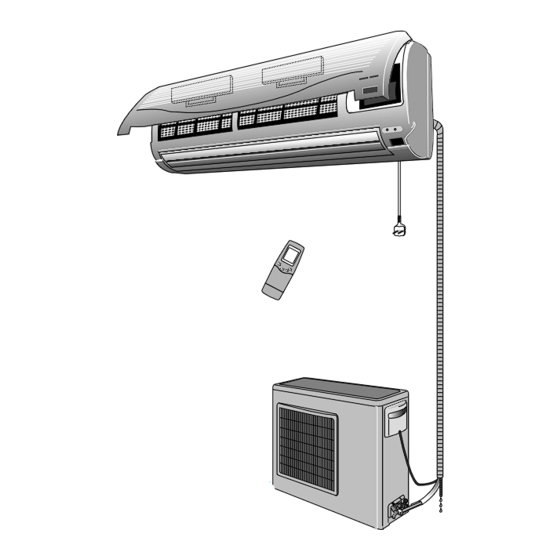
Page 8: Operation
OPERATION 1) SYSTEM DIAGRAM Indoor Unit ROOM AIR INLET AIR FILTER ELECTROSTATIC/ACTIVE CARBON FILTER REMOTE CONTROL SIGNAL RECEIVER AIR SWING FLAP VERTICAL LOUVER ROOM AIR OUTLET LCD REMOTE CONTROL OUTDOOR AIR OUTLET OUTDOOR AIR INLET INDOOR AND OUTDOOR CONNECTION Outdoor Unit DRAIN HOSE... -
Page 9: Indoor Unit Display
2) INDOOR UNIT DISPLAY AND SWITCH PANEL Indoor Unit Display (Green) : Lights during the operation. (Orange) : Lights during timer mode. Switches Panel EMERG. TEST . EMERG. button : Can be used when the remote control is missed or inoperative. . - Page 10 3) NAMES AND FUNCTIONS OF REMOTE CONTROLLER • 42HWG007/009/012/018/024 HWG195C/225C/305C/455C/605C SWING SLEEP I / O TEMP MODE FLAP RST TA CLOCK EVERYDAY HOUR MINUTE LR03(AM4)1.5V TIMER CANCEL LR03(AM4)1.5V I/O BUTTON HOUR/MINUTE SETTING BUTTONS TEMPERATURE SETTING BUTTONS SET AND CANCEL SLEEP TIMER BUTTON BUTTONS OPERATION MODE SELECTING EVERYDAY TIMER BUTTON...
- Page 11 • 42HQG007/009/012/018/024 & HWG195H/225H/305H/455H/605H SWING SLEEP I / O TEMP FLAP MODE RST TA CLOCK EVERYDAY HOUR MINUTE LR03(AM4)1.5V TIMER CANCEL LR03(AM4)1.5V I/O BUTTON HOUR/MINUTE SETTING BUTTONS TEMPERATURE SETTING BUTTONS SET AND CANCEL SLEEP TIMER BUTTON BUTTONS OPERATION MODE SELECTING EVERYDAY TIMER BUTTON BUTTON CURRENT TIME ADJUSTING...
-
Page 12: Indoor Fan
I/O BUTTON Press this button to start operation. (A receiving beep is heard). Press this button again to stop operation. (A receiving beep is heard). When pressing the I/O button immediately after turning the unit off, the compressor will not operate for 3 minutes to keep it from overloading. TEMPERATURE SETTING BUTTON Set the temperature to a desired room temperature, then unit will keep the tempera-ture to the set temperature. - Page 13 FAN SPEED SELECTING BUTTON Press this button to select the desired fan speed. The indoor fan will operate at the selected fan speed. (AUTO, LOW, MED, HIGH) When you select “AUTO”, the fan speed is controlled by microcomputer of the unit. FLAP CONTROL BUTTON Controls the discharge air flow direction up and down.
- Page 14 4) REMOTE CONTROLLER DISPLAY • 42HWG007/009/012/018/024 & HWG195C/225C/305C/455C/605C Indicates the selected temperature. Indicates flap modes AUTO FLAP SWING SLEEP SLEEP EVERYDAY EVERYDAY AUTO Automatic position User selected position Swing up and down SWING Indicates the selected operating mode. Indicates the reserved status of SLEEP timer or EVERYDAY timer.
- Page 15 • 42HQG007/009/012/018/024 & HWG195/225/305H/455H/605H Indicates the selected temperature. Indicates flap modes FLAP AUTO AUTO FLAP SWING SWING SLEEP EVERYDAY SLEEP EVERYDAY AUTO Automatic position User selected position Swing up and down SWING Indicates the selected operating mode. Indicates the reserved status of SLEEP timer or EVERYDAY timer.
- Page 16 5) DESCRIPTION OF FUNCTIONS (1) Timer Mode General features – If user changes time of ON/OFF timer during timer function execution, the timer will be changed according to the new set time. – The other mode changes are enabled during timer function execution. –...
- Page 17 Combination of ON and OFF Timer – If user sets time with ON/OFF timer, the unit will start and stop at the set time. UNIT ON UNIT ON UNIT OFF OFF TIME ON TIME HOUR NOTE : • The current time is not indicated during the reservation of ON/OFF timer. •...
- Page 18 EVERYDAY-Timer – The EVERYDAY timer can be set in case of reserved condition of the combined ON and OFF timer or the combined ON and SLEEP timer. – If user sets time with EVERYDAY timer, the unit will repeat the combined ON and OFF timer reservation everyday.
- Page 19 (3) Dry Mode – This operation eliminates moisture effectively by operating the compressor, indoor and outdoor fan motor intermittently, so that the room temperature is maintained at set temperature. – Determination of dry mode BLOCK based on Room temp. and Set temp. (Set temp.
- Page 20 (4) Automatic Operation (42HQG007/009/012/018/024 & HWG195H/225H/305H/455H/605H) – If the unit is set to ‘AUTO’ mode, the unit operates automatically by selecting COOL or HEAT mode according to the room temperature to keep the room temperature comfortable. ROOM TEMPERATURE COOLING MODE T.S+1°...
- Page 21 (5) Discharge Air Louver Control Up and Down Control The air discharge direction can be controlled to swing up and down and can be fixed at preferred position or automatic position by the remote control. CLOSE FLAP AUTO SWING Remote control Fixed Swing Range Auto Position...
- Page 22 Left and Right Control If you want to adjust the direction of the discharge air to left or right, adjust the vertical louver with the handle after opening the flap. HANDLE NOTE • Please do not fix the flap at position for a long time, as this position minimizes air circulation resulting in uneven room temperature.
- Page 23 Indoor Coil High Temperature Protection – The system performs this function only in HEAT mode. – If the indoor coil temperature is greater than or equal to 57°C, the outdoor fan turns off and does not turn on until the indoor coil temperature is less than or equal to 49°C. –...
- Page 24 2) Preceding condition is a) The first step is “the accumulated compressor on time is greater than 30 minutes.” b) Second step is the one of below two -The first condition ; If Real-Delta>Defrost-Delta for 60 continuous seconds and the following conditions are all true then defrost initiates. )The outdoor coil temperature<-2°C )The compressor has been on continuously for 15 minutes.
- Page 25 ERROR DISPLAY ALLOWED (RANK) CONTENTS PATTERN MODES MICOM MEMORY NOTHING SYSTEM RESET 0.5 sec (2 times) ROOM AIR FAN ONLY THERMISTOR MODE MALFUNCTION 3 sec 3 sec 0.5 sec (3 times) INDOOR COIL FAN ONLY THERMISTOR MODE MALFUNCTION 3 sec 3 sec 0.5 sec (4 times) OUTDOOR COIL...
-
Page 26: Remote Control
Auto restart Mode – When the power failure is happened during the system operating, the micro will memo- rize the operation mode and the unit operates automatically according to the previous operating mode after the power is recovered. – Whenever the unit receives remote signal, the micom will memorize the following opera- tion •... - Page 27 (8) DST Interface – According to input of selecting address configuration of indoor unit PCB, the one of below functions is assigned. Address configuration Functions DST Interface available DST Interface not available – The applicable connector for these functions is CN18 of indoor unit PCB. DST Interface 1) The DST(Dealer Service Tool) is an application program used to verify a defec- tive control board in Air Conditioner...
- Page 28 • Fan Speed: AUTO • Timer mode: Disable • Discharge Air Direction: Preset location according to 'COOL' or 'HEAT' mode. Test operation – Perform TEST operation after the units have been installed in position and gas leak test has been completed. –...
- Page 29 – The life time of optional Active carbon filter is about 2 years and that of optional Electrostatic filter is about 3 months.(In case of electrostatic filter, refer to color sample sticker indicating pollution level.) These filters cannot be recycled. –...
-
Page 30: Wiring Diagram
WIRING DIAGRAM 1) 42HWG007/009/012 & HWG195/225/305C-SERIES INDOOR UNIT LEGEND K: RELAY IDFM: INDOOR FAN MOTOR MSW: MAIN SWITCH TB: TERMINAL BLOCK FCU: FAN COIL UNIT HS: HALL (RPM) SENSOR TP: THERMAL PROTECTOR CDU: CONDENSING UNIT TRANS: TRANSFORMER CN: CONNECTOR RA Th: ROOM AIR THERMISTOR COMP: COMPRESSOR EC1: FAN MOTOR CAPACITOR MOV: METAL OXIDE VARISTOR... - Page 31 2) 42HQG007/009/012 & HWG195/225/305H-SERIES INDOOR UNIT LEGEND K: RELAY IDFM: INDOOR FAN MOTOR MSW: MAIN SWITCH TB: TERMINAL BLOCK FCU: FAN COIL UNIT HS: HALL (RPM) SENSOR TP: THERMAL PROTECTOR CDU: CONDENSING UNIT ODFM: OUTDOOR FAN MOTOR CN: CONNECTOR RA Th: ROOM AIR THERMISTOR COMP: COMPRESSOR EC1: FAN MOTOR CAPACITOR MOV: METAL OXIDE VARISTOR...
- Page 32 3) 42HWG018/024 & HWG455C/605C-SERIES INDOOR UNIT LEGEND K: RELAY IDFM: INDOOR FAN MOTOR MSW: MAIN SWITCH TB: TERMINAL BLOCK FCU: FAN COIL UNIT HS: HALL (RPM) SENSOR TP: THERMAL PROTECTOR CDU: CONDENSING UNIT TRANS: TRANSFORMER CN: CONNECTOR RA Th: ROOM AIR THERMISTOR COMP: COMPRESSOR EC1: FAN MOTOR CAPACITOR MOV: METAL OXIDE VARISTOR...
- Page 33 4) 42HQG018/024 & HWG455H/605H-SERIES INDOOR UNIT LEGEND K: RELAY IDFM: INDOOR FAN MOTOR MSW: MAIN SWITCH TB: TERMINAL BLOCK FCU: FAN COIL UNIT HS: HALL (RPM) SENSOR TP: THERMAL PROTECTOR CDU: CONDENSING UNIT ODFM: OUTDOOR FAN MOTOR CN: CONNECTOR RA Th: ROOM AIR THERMISTOR COMP: COMPRESSOR EC1: FAN MOTOR CAPACITOR MOV: METAL OXIDE VARISTOR...
-
Page 34: Refrigerant Cycle
REFRIGERANT CYCLE 1) 42HWG007/009/012/018/024 & HWG195C/225C/305C/455C/605C INDOOR UNIT Evaporator Cross flow fan Connecting pipe Service valve Service valve Expansion Accumulator device Compressor Condenser Propeller fan OUTDOOR UNIT Refrigerant flow... - Page 35 2) 42HQG007/009/012/018/024 & HWG195H/225H/305H/455H/605H INDOOR UNIT lndoor heat exchanger Cross flow fan Connecting pipe Service valve Service valve Reversing valve Accumulator Accurater Compressor outdoor heat exchanger Propeller fan OUTDOOR UNIT Refrigerant flow (cooling) Refrigerant flow (heating)
-
Page 36: Control Block Diagram
CONTROL BLOCK DIAGRAM 1) 42HWG007/009/012/018/024 & HWG195C/225C/305C/455C/605C... - Page 37 2) 42HQG007/009/012/018/024 & HWG195/225/305/455/605H-SERIES...
-
Page 38: Electric Circuit Diagram
ELECTRIC CIRCUIT DIAGRAM 1) FUNCTIONAL CIRCUIT DIAGRAM 42HWG007/009/012 & HWG195/225/305C-SERIES • After the power I/O button is pressed once, the Power-relay and AC SWITCH are turned on or off per the remote control setpoint. – AC SWITCH U9 is controlled per the fan speed selection. –... - Page 39 b 42HQG007/009/012 & HWG195/225/305H-SERIES • After the power I/O button is pressed once, the Power-relay, relays and AC SWITCH are turned on or off per the remote control setpoint. – AC SWITCH U9 is controlled per the fan speed selection. –...
- Page 40 42HWG018/024 & HWG455/605C-SERIES • After the power I/O button is pressed once, the relay and AC SWITCH are turned on or off per the remote control setpoint. – AC SWITCH U9 is controlled per the fan speed selection. – Relay K1 is controlled per the operation mode selection. •...
- Page 41 42HQG018/024 & HWG455/605H-SERIES • After the power I/O button is pressed once, relays and AC SWITCH are turned on or off per the remote control setpoint. – AC SWITCH U9 is controlled per the fan speed selection. – Relay K1, K2, K3 are controlled per the operation mode selection. •...
- Page 42 2) PCB CIRCUIT DIAGRAM a MAIN CONTROL PART 42HWG007/009/012, 42HQG007/009/012, HWG195/225/305C, HWG195/225/305H...
- Page 43 b MAIN CONTROL PART 4 2 H W G 0 1 8 / 0 2 4 , 4 2 H Q G 0 1 8 / 0 2 4 , H W G 4 5 5 / 6 0 5 C , H W G 4 5 5 / 6 0 5 H...
- Page 44 INDEX DESCRIPTION STEPPING MOTOR DRIVING STEPPING MOTOR RPM SENSOR INPUT HALL (RPM) SENSOR FUNCTION CONFIGURATION TEMPERATURE SENSING T H E R M I S T O R “EMERGENCY” OR “TEST” SIGNAL INPUT ADDRESS SELECTION INPUT SIGNAL RECEIVER & INDICATOR LAMP DRIVING SIGNAL RECEIVER &...
- Page 45 c REMOTE CONTROL PART...
- Page 46 3) PCB PATTERN DIAGRAM a CONTROL PCB (SOLDERING SIDE) 42HWG007/009/012, 42HQG007/009/012, HWG095/225/305C, HWG195/225/305H...
- Page 47 b CONTROL PCB (COMPONENTS SIDE) 4 2 H W G 0 0 7 / 0 0 9 / 0 1 2 , 4 2 H Q G 0 0 7 / 0 0 9 / 0 1 2 , H W G 1 9 5 / 2 2 5 / 3 0 5 C , H W G 1 9 5 / 2 2 5 / 3 0 5 H...
- Page 48 c CONTROL PCB (SOLDERING SIDE) 42HWG018/024, 42HQG018/024, HWG455/605C, HWG455/605H...
- Page 49 d CONTROL PCB (COMPONENTS SIDE) 4 2 H W G 0 1 8 / 0 2 4 , 4 2 H Q G 0 1 8 / 0 2 4 , H W G 4 5 5 / 6 0 5 C , H W G 4 5 5 / 6 0 5 H...
- Page 50 e Display and Receiver PCB (Component side) 4) LCD PANEL TEST a Selecting the test mode : Press the LCD test key (K15) in remote control PCB during OFF mode Test mode cancellation – After the test program is completed. –...
-
Page 51: Key Components Of Electronic Circuit
KEY COMPONENTS OF ELECTRONIC CIRCUIT 1) U1 (MICOM) P20/SI1 P21/SO1 P22/SCK1 P17/AN17 P16/AN16 P23/STB P15/AN15 P24/BUSY P14/AN14 P25/SI0/SB0 P26/SO0/SB1 P13/AN13 P27/SCK0 P12/AN12 P11/AN11 P30/TO0 P10/AN10 P31/TO1 P32/TO2 P04/XT1 P33/TI1 P34/TI2 P35/PCL P36/BUZ P40/AD0 P03/INTP3 P02/INTP2 P41/AD1 P42/AD2 P01/INTP1 P43/AD3 P00/INTP0/TI0 P44/AD4 RESET P45/AD5... - Page 52 2) U2 (TD62083AP): DARLINGTON ARRAYS PIN CONNECTION (TOP VIEW) SCHEMATICS (EACH DRIVER) COMMON COMMON 2.7k OUTPUT INPUT 7.2k 3) U4 (14584B): SCHUMITT TRIGGER INVERTER LOGIC DIAGRAM EQUIVALENT CIRCUIT SCHEMATIC (1/2 OF CIRCUIT SHOWN) =PIN14 Vss=PIN7 4) U5 (NM24C02): EEPROM Dual-In-Line Package(N) Pin Names and SO Package(M8) Device Address Inputs...
- Page 53 5) U6 (MAX 1232EPA): RESET I.C MAX1232 5%/10% RESET TOLERANCE GENERATOR SELECT PB RST 8 Vcc 7 ST MAX1232 PB RST 6 RST DEBOUNCE 5 RST WATCHDOG WATCHDOG TIMEBASE TIMER SELECT 6) U7 (7812ACT)/U8 (7805CT): VOLTAGE REGULATOR SCHEMATIC DIAGRAM TSUFFIX INPUT PLASTIC PACKAGE 100K...
- Page 54 7) U9 (TSA3100J(v)): AC SWITCH 25.2 0.2 10.16 0.6 7.62 0.6 2.54 0.3 0.55 0.15 1.1 0.15 1 : AC OUTPUT(MT2) 4 : DC INPUT(+) 2 : AC OUTPUT(MT1) 5 : DC INPUT(-) 3 : GATE * : RESIN FLASH 8) U10 (TLP621): PHOTO-COUPLER TLP621 TLP621...
- Page 55 9) RU1: REMOCON MICOM OSC3 SEG31 SEG30 OSC2 SEG29 OSC1 SEG28 N.C. SEG27 SEG26 SMC621A AOUT SEG25 AMPM SEG24 AMPP Index SEG23 RSTOUT SEG22 R33(REM) SEG21 SEG20 RESET SEG19 SEG18 SEG17 N.C.:No connection 10) LCD (E-30294) 1.0 +0 30.0 –0.2 2.7 –0.3 28.0 -0 2.0 +0...
-
Page 56: Checking And Repairing Of Electric Parts
CHECKING AND REPAIRING OF ELECTRIC PARTS Operating Procedure Photos 1) Measuring insulation resistance of indoor fan motor Remove the fan motor connector from PCB. b Connect clip to the ground terminal connecting Green/Yellow line. Green/Yellow c M e a s u r e i n s u l a t i o n r e s i s t a n c e b y c o n n e c t i n g terminal of insulation ohmmeter to the arbitrary fan motor connector. - Page 57 Operating Procedure Photos 4) Checking power transformer a. Remove power transformer from control box. b. Set the range of resistance measurement of multimeter to "x1Ω" c. Measure lead line resistance between the yellow and yellow and between the brown and blue. d.
- Page 58 9) Thermistor temperature vs. resistance table a Room air thermistor TEMP(ºC) R(K ) TEMP(ºC) R(K ) TEMP(ºC) R(K ) TEMP(ºC) R(K ) 0 . 8 5 0 8 2 . 9 9 3 1 4 . 3 7 - 4 0 1 1 3 .
- Page 59 b Indoor coil & Outdoor coil thermistor TEMP(ºC) R(K ) TEMP(ºC) R(K ) TEMP(ºC) R(K ) TEMP(ºC) R(K ) 1 . 2 1 8 5 . 1 1 8 3 1 . 0 4 - 4 0 3 3 9 . 9 1 .
-
Page 60: Trouble Shooting
TROUBLE SHOOTING... - Page 61 Note 1) a Neither indoor unit nor outdoor unit runs Check the following point first (There is following case in normal operation). a. Is the timer mode set to “TIMER-OFF” and the timer had passed? b Neither outdoor fan nor compresssor runs while indoor fan runs Check following points first (There are following cases in normal operation).
-
Page 62: Disassembly Instructions
DISASSEMBLY INSTRUCTIONS • INDOOR UNIT P R O C E D U R E S P H O T O S 1. INDOOR UNIT (1) Turn off operation of the air conditioner and disconnect the power cord from the wall outlet. 2. - Page 63 P R O C E D U R E S P H O T O S 5. Removing the indoor coil. (1) Turn the unit over and you will find one screw for insert b o d y . (2) Remove one screw and detach insert body. (fig. 7) (3) Turn the unit over again and remove three screws from the coil.
-
Page 64: Exploded Diagram And Parts List
EXPLODED DIAGRAM AND PARTS LIST... - Page 65 C O O L C O O L N O . PART NAME REMARK 42HWG007 42HWG009 H W G 1 9 5 C H W G 2 2 5 C BOX AS, CONTROL 1 - 1 TRANSFORMER 1 - 2...
- Page 66 • 42HQG007/009, HWG195H/225H HEATPUMP HEATPUMP HEATPUMP HEATPUMP PART NAME REMARK 42HQG007 42HQG009 H W G 1 9 5 H H W G 2 2 5 H BOX AS, CONTROL 1 - 1 TRANSFORMER 1 - 2 BOX, CONTROL 1 - 3 PCB AS, T/B 1 - 4 PCB AS, DISPLAY...
- Page 67 • 42HWG012, HWG305C, 42HQG012, HQG305H COOL COOL HEATPUMP HEATPUMP PART NAME REMARK 42HWG012 H W G 3 0 5 C 42HQG012 42HQG305H BOX AS, CONTROL 1 - 1 TRANSFORMER 1 - 2 BOX, CONTROL 1 - 3 PCB AS, T/B 1 - 4 PCB AS, DISPLAY 1 - 5...
- Page 68 • 42HWG018/024, HWG455C/605C COOL COOL COOL COOL PART NAME REMARK 42HWG018 42HWG024 H W G 4 5 5 C H W G 6 0 5 C BOX AS, CONTROL 1 - 1 TRANSFORMER 1 - 2 BOX, CONTROL 1 - 3 PCB AS, T/B 1 - 4 PCB AS, DISPLAY...
- Page 69 • 42HQG018/024, HQG455H/605H HEATPUMP HEATPUMP HEATPUMP HEATPUMP PART NAME REMARK 42HQG018 42HQG024 HQG455H HQG605H BOX AS, CONTROL 1 - 1 TRANSFORMER 1 - 2 BOX, CONTROL 1 - 3 PCB AS, T/B 1 - 4 PCB AS, DISPLAY 1 - 5 BRACKET, LED 1 - 6 PCB AS 1, CONTROL...
- Page 70 • REMOTE CONTROL 42HWG007/009/012/018/024, 42HQG007/009/012/018/024, HWG195/225/305/455/605C, HWG195/225/305/455/605H C O O L C O O L HEATPUMP HEATPUMP N O . PART NAME 42HWG007/009/ HWG195/225/305/ 42HQG007/009/ HWG195/225/305/ REMARK 012/018/024 455/605C 012/018/024 455/605H BOX 1, REMOCON DISPLAY, LCD BOX 2, REMOCON RUBBER 1, SWITCH PCB AS, REMOCON LCD DISPLAY ZEBRA CONTACT...
- Page 71 General notes 1. Shown performances are valid under the following conditions: a) indoor / outdoor tubing length 6 m b) indoor / outdoor unit level difference O m c) indoor fan running at high speed 2. Correction factors for different tubing length and / or different indoor fan speed are shown in Table 1, Table 2a and 2b.
-
Page 72: Extending Ratings
EXTENDING RATINGS 1) TABLE 1 CORRECTION FACTOR OF COOLING AND HEATING SYSTEM PERFORMANCES DUE TO INDOOR / OUTDOOR PIPING LENGTH UNIT PIPING LENGTH SIZE 1.02 0.97 0.93 1.02 0.97 0.93 1.02 0.97 0.93 1.01 0.99 0.97 0.95 1.01 0.97 0.95 0.93... - Page 73 2) TABLE 2 CORRECTION FACTORS OF SYSTEM PERFORMANCES DUE TO INDOOR UNIT FAN SPEED 2A - COOLING MODE UNIT COOLING CAPACITY POWER SIZE SPEED TOTAL SENSIBLE INPUT 1.00 1.00 1.00 0.98 0.93 0.99 0.96 0.87 0.98 1.00 1.00 1.00 0.98 0.93 0.99 0.96...
-
Page 74: Indoor Coil
3) TABLE 3 TOTAL SENSIBLE CAPACITY CORRECTION FACTOR (SHC) ° BYPASS DRY BULB TEMPERATURE FOR AIR ENTERING IN THE INDOOR COIL ( FACTOR 24,5 25,5 26,5 27,5 28,5 29,5 CORRECTION FACTOR (CF) 6,78 3,36 2,79 2,23 1,67 1,11 0,55 0,00 0,56 1,11 1,67 2,22 2,76 3,30 5,37 6,23 3,09 2,57 2,06 1,54 1,02 0,51 0,00 0,51 1,02 1,53 2,04 2,55 3,05 4,98 4,68 2,76 2,30 1,84 1,38 0,92 0,46 0,00 0,46 0,91 1,36 1,80 2,23 2,65 4,43 SHC is calculated with air entering on the indoor coil at 27°C db;... - Page 75 42HWG007 + 38GL07 Cooling mode DRY BULB AIR TEMPERATURE (°C) WET BULB AIR TEMPERATURE (°C) ENTERING ENTERING EVAPORATOR CONDENSER 2.05 2.13 2.18 2.20 2.23 1.90 1.69 1.44 1.21 0.99 0.48 0.48 0.49 0.49 0.49 2.04 2.14 2.22 2.26 2.34 1.94 1.73 1.50 1.26...
- Page 76 42HQG007 + 38YL07 Cooling mode DRY BULB AIR TEMPERATURE (°C) WET BULB AIR TEMPERATURE (°C) ENTERING ENTERING EVAPORATOR CONDENSER 2.08 2.12 2.15 2.20 2.23 1.56 1.35 1.14 0.96 0.76 0.50 0.50 0.50 0.51 0.51 2.06 2.14 2.18 2.25 2.27 1.56 1.40 1.18 1.00...
- Page 77 42HWG009 + 38GL09 Cooling mode DRY BULB AIR TEMPERATURE (°C) WET BULB AIR TEMPERATURE (°C) ENTERING ENTERING EVAPORATOR CONDENSER 2.49 2.61 2.68 2.74 2.83 2.26 2.02 1.73 1.48 1.24 0.65 0.67 0.67 0.68 0.69 2.43 2.55 2.67 2.75 2.84 2.24 2.02...
- Page 78 42HQG009 + 38YL09 Cooling mode DRY BULB AIR TEMPERATURE (°C) WET BULB AIR TEMPERATURE (°C) ENTERING ENTERING EVAPORATOR CONDENSER 2.37 2.49 2.51 2.59 2.61 2.13 1.91 1.60 1.38 1.14 0.66 0.68 0.68 0.69 0.69 2.36 2.43 2.54 2.59 2.66 2.16 1.90 1.66 1.39...
- Page 79 42HWG012 + 38GL12 Cooling mode DRY BULB AIR TEMPERATURE (°C) WET BULB AIR TEMPERATURE (°C) ENTERING ENTERING EVAPORATOR CONDENSER 3.27 3.45 3.60 3.77 3.86 2.99 2.70 2.36 2.06 1.71 0.81 0.83 0.84 0.86 0.87 3.18 3.34 3.52 3.67 3.80 2.96 2.66 2.34 2.03...
- Page 80 42HQG012 + 38YL12 Cooling mode DRY BULB AIR TEMPERATURE (°C) WET BULB AIR TEMPERATURE (°C) ENTERING ENTERING EVAPORATOR CONDENSER 3.21 3.36 3.52 3.62 3.65 2.88 2.57 2.25 1.94 1.59 0.82 0.83 0.85 0.86 0.86 3.12 3.28 3.39 3.58 3.65 2.85 2.55 2.20 1.94...
- Page 81 42HWG018 + 38GL18 Cooling mode DRY BULB AIR TEMPERATURE (°C) WET BULB AIR TEMPERATURE (°C) ENTERING ENTERING EVAPORATOR CONDENSER 4.45 4.47 4.57 4.50 4.53 4.33 3.69 3.19 2.63 2.20 1.20 1.19 1.21 1.20 1.20 4.49 4.65 4.71 4.76 4.79 4.44 3.94 3.33 2.79...
- Page 82 42HQG018 + 38YL18 Cooling mode DRY BULB AIR TEMPERATURE (°C) WET BULB AIR TEMPERATURE (°C) ENTERING ENTERING EVAPORATOR CONDENSER 4.85 4.96 5.03 5.11 5.13 4.57 4.03 3.39 2.84 2.33 1.11 1.11 1.12 1.12 1.12 4.83 4.93 5.14 5.26 5.29 4.60 4.10 3.54 2.96...
- Page 83 42HWG024 + 38GL24 Cooling mode DRY BULB AIR TEMPERATURE (°C) WET BULB AIR TEMPERATURE (°C) ENTERING ENTERING EVAPORATOR CONDENSER 6.34 6.62 6.82 7.03 7.16 6.13 5.48 4.73 4.04 3.37 1.61 1.64 1.65 1.67 1.68 6.25 6.47 6.76 6.91 7.13 6.12 5.45 4.75 4.00...
- Page 84 42HQG024 + 38YL24 Cooling mode DRY BULB AIR TEMPERATURE (°C) WET BULB AIR TEMPERATURE (°C) ENTERING ENTERING EVAPORATOR CONDENSER 6.40 6.67 6.89 7.15 7.33 6.27 5.63 4.83 4.15 3.46 1.62 1.64 1.66 1.68 1.69 6.27 6.50 6.77 7.15 7.23 6.24 5.60 4.84 4.19...
- Page 85 42HQG007 + 38YL07 Heating mode TEMPERATURE (°C) DRY BULB AIR TEMPERATURE ENTERING AIR ENTERING OUTDOOR COIL (°C) INDOOR COIL 0.81 1.10 1.27 1.55 1.86 2.19 2.40 2.75 3.04 0.75 1.00 1.15 1.37 1.60 2.19 2.40 2.75 3.04 0.46 0.49 0.51 0.55 0.59 0.63...
- Page 86 42HQG012 + 38YL12 Heating mode TEMPERATURE (°C) DRY BULB AIR TEMPERATURE ENTERING AIR ENTERING OUTDOOR COIL (°C) INDOOR COIL 1.20 1.63 1.89 2.37 2.83 3.33 3.62 4.12 4.62 1.10 1.49 1.72 2.10 2.45 3.33 3.62 4.12 4.62 0.67 0.72 0.75 0.82 0.87 0.94...
- Page 87 42HQG024 + 38YL24 Heating mode TEMPERATURE (°C) DRY BULB AIR TEMPERATURE ENTERING AIR ENTERING OUTDOOR COIL (°C) INDOOR COIL 3.76 4.43 4.86 5.65 6.36 7.32 7.76 8.42 8.84 3.45 4.06 4.40 5.00 5.51 7.32 7.76 8.42 8.84 1.72 1.81 1.87 1.99 2.11 2.29...
-
Page 88: Dip Switch Configuration For Eto
DIP SWITCHES CONFIGURATION Every unit has a set of 6 (six) dip switches inside its board for configuration purpose. Due to theirs location, these switches must be configured only on the assembly line. The meanings of these switches are down described : Microswitch Meaning Note... - Page 89 Carrier Corporation P/N:42KG8K54600 (Version 1.0)
Need help?
Do you have a question about the 42HWG009 and is the answer not in the manual?
Questions and answers