Table of Contents
Advertisement
FILE NO. SVM-05010-2
SERVICE MANUAL
AIR CONDITIONER
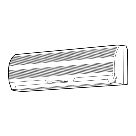
SPLIT WALL TYPE
42CJR024-723 / 38CJR024-723
42CJR018-723 / 38CJR018-723
42TAR024X-723 / 38TAR024X-723
42TAR018-723 / 38TAR018-723
42HNR024-713 / 38HNR024-713
42HNR018-713 / 38HNR018-713
18 Class
18 Class
24 Class
(Heat pump model)
(Cooling only model)
Revised Aug, 2005
Advertisement
Table of Contents
Troubleshooting

Related Manuals for Carrier 42CJR024-723


Summary of Contents for Carrier 42CJR024-723
-
Page 1: Service Manual
FILE NO. SVM-05010-2 SERVICE MANUAL AIR CONDITIONER SPLIT WALL TYPE 42CJR024-723 / 38CJR024-723 42CJR018-723 / 38CJR018-723 42TAR024X-723 / 38TAR024X-723 42TAR018-723 / 38TAR018-723 42HNR024-713 / 38HNR024-713 42HNR018-713 / 38HNR018-713 18 Class 18 Class 24 Class (Heat pump model) (Cooling only model) -
Page 2: Table Of Contents
Outdoor Unit (42CJR018-723, 42HNR018-713, 42HNR024-713) Outdoor Unit (38CJR024-723, 38TAR024X-723, 38TAR018-723, 38HNR024-713) Outdoor Unit (38CJR018-723) Outdoor Unit (38HNR018-713) WIRING DIAGRAM 42CJR024-723 / 38CJR024-723, 42TAR024X-723 / 38TAR024X-723 42CJR018-723 / 38CJR018-723 42TAR018-723 / 38TAR018-723 42HNR018-713 / 38HNR018-713 42HNR024-713 / 38HNR024-713 SPECIFICATION OF ELECTRICAL PARTS... - Page 3 FILE NO. SVM-05010 INSTALLATION PROCEDURE Safety Cautions Installation Diagram of Indoor and Outdoor Units Installation Indoor Unit Outdoor Unit How to Set Remote Control Selector Switch Others TROUBLESHOOTING CHART Troubleshooting Procedure Basic Check Items Primary Judgement Self-Diagnosis by Remote Control (Check Code) How to Diagnose Faulty Parts Troubleshooting for Indoor Unit Troubleshooting for Wiring (Interconnect cable and Serial Signal Wire)
-
Page 4: Specifications
FILE NO. SVM-05010 1. SPECIFICATIONS 42CJR024-723 / 38CJR024-723 42TAR024X-723 / 38TAR024X-723 MODEL ITEM Cooling Capacity 220V 240V 220V 6.40 6.45 6.40 Phase 1∅ Power source 220 – 240 Power consumption 2420 2510 2250 Power factor 220V 240V 220V R unning current 0.3/10.9... - Page 5 FILE NO. SVM-05010 42CJR018-723 / 38CJR018-723 42TAR018-723 / 38TAR018-723 MODEL ITEM Cooling 220V 240V 220V Capacity 5.20 5.25 5.10 Phase 1∅ Power source 220 – 240 Power consumption 1920 2000 1560 Power factor 220V 240V 220V Running current 0.2/9.25 0.2/9.50 0.3/6.94 Indoor/Outdoor Starting current...
- Page 6 FILE NO. SVM-05010 42HNR024-713 42HNR018-713 MODEL 38HNR024-713 38HNR018-713 Cooling Heating ITEM Heating Cooling 220 V 220 V 240 V 220 V 240 V 220 V 240 V 240 V Capacity 5.80 6.30 6.90 5.05 5.90 6.30 6.80 5.05 Phase ∅1 Power source 220 −...
- Page 7 7°C Outdoor unit inlet air temperature (WB) 24°C 6°C Note : 2 Charge refrigerant according to the table below. 42CJR024-723 / 38CJR024-723 42CJR018-723 / 38CJR018-723 Refrigerant 42TAR024X-723 / 38TAR24X-723 42TAR018-723 / 38TAR18-723 42HNR024-713 / 38HNR024-713 42HNR018-713 / 38HNR018-713 No need to charge...
-
Page 8: Construction Views
FILE NO. SVM-05010 2. CONSTRUCTION VIEWS 2-1. Indoor Unit (42CJR024-723, 42TAR024X-723, 42TAR018-723) Back body Front panel Grille inlet Knock out system Knock out system 75 65 Drain hose (0.54 m) Connecting pipe (0.39 m) Connecting pipe (0.49 m) (Flare ∅15.88) (Flare ∅6.35) -
Page 9: Outdoor Unit (42Cjr018-723, 42Hnr018-713, 42Hnr024-713)
FILE NO. SVM-05010 2-2. Outdoor Unit (42CJR018-723, 42HNR018-713, 42HNR024-713) Back body Front panel Grille inlet Knock out system Knock out system 75 65 Drain hose (0.54 m) Connecting pipe (0.39 m) Connecting pipe (0.49 m) (Flare ∅12.7) (Flare ∅6.35) 763.5 (For stud bolt ∅6) (For stud bolt ∅8 −... -
Page 10: Outdoor Unit (38Cjr024-723, 38Tar024X-723, 38Tar018-723,38Hnr024-713)
FILE NO. SVM-05010 2-3. Outdoor Unit (38CJR024-723, 38TAR024X-723, 38TAR018-723,38HNR024-713) – 9 –... -
Page 11: Outdoor Unit (38Cjr018-723)
FILE NO. SVM-05010 2-4. Outdoor Unit (38CJR018-723) 32.5 Detail Drawing (Back Leg) B Detail Drawing (Front Leg) ∅6 Hole ∅6 Hole ∅11x14 Hole R5.5 ∅30 Drain outlet 2-∅11x14 Hole (For ∅8-∅10 anchor bolt) FAN GUARD ∅436 COVER PV Electrical part cover Liquid side (Flare ∅6.35) Gas side... -
Page 12: Outdoor Unit (38Hnr018-713)
FILE NO. SVM-05010 2-5. Outdoor Unit (38HNR018-713) – 11 –... -
Page 13: Wiring Diagram
FILE NO. SVM-05010-1 3. WIRING DIA GRAM 3-1. 42CJR024-723 / 38CJR024-723, 42TAR024X-723 / 38TAR024X-723 COLOR IDENTIFICATION BRW : BROWN RED : RED Louver WHI : WHITE motor YEL : YELLOW Infrared rays receive BLU : BLUE and Indication parts BLK : BLACK... -
Page 14: 42Cjr018-723 / 38Cjr018-723
FILE NO. SVM-05010-1 3-2. 42CJR018-723 / 38CJR018-723 COLOR IDENTIFICATION BRW : BROWN RED : RED Louver WHI : WHITE motor YEL : YELLOW Infrared rays receive BLU : BLUE and Indication parts BLK : BLACK 7 8 9 GRY : GRAY CN25 1 2 3 4 PNK : PINK... -
Page 15: 42Tar018-723 / 38Tar018-723
FILE NO. SVM-05010-1 3-3. 42TAR018-723 / 38TAR018-723 COLOR IDENTIFICATION BRW : BROWN RED : RED Louver WHI : WHITE motor YEL : YELLOW Infrared rays receive BLU : BLUE and Indication parts BLK : BLACK 7 8 9 GRY : GRAY CN25 1 2 3 4 PNK : PINK... -
Page 16: 42Hnr018-713 /38Hnr018-713
FILE NO. SVM-05010-1 3-4 . 42HNR018-713 /38HNR018-713 COLOR IDENTIFICATION BRW : BROWN RED : RED WHI : WHITE Louver YEL : YELLOW motor BLU : BLUE Infrared rays receive BLK : BLACK and Indication parts GRY : GRAY 1 2 3 CN25 1 2 3 PNK : PINK... -
Page 17: 42Hnr024-713 / 38Hnr024-713
FILE NO. SVM-05010-1 3-5. 42HNR024-713 / 38HNR024-713 COLOR IDENTIFICATION BRW : BROWN RED : RED WHI : WHITE YEL : YELLOW Louver BLU : BLUE motor Infrared rays receive BLK : BLACK and Indication parts GRY : GRAY 1 2 3 PNK : PINK CN25 1 2 3... -
Page 18: Specification Of Electrical Parts
FILE NO. SVM-05010 4. SPECIFICATION OF ELECTRICAL PARTS 4-1. Indoor Unit (42CJR024-723, 42CJR018-723, 42TAR024X-723, 42TAR018-723) Parts name Type Specifications AC 200 − 240V, 31W Fan motor (for indoor) AFS-220-31A Thermo sensor (TA-sensor) ——— 10 kΩ at 25°C µRM1260V Micro Power Module (M01) -
Page 19: Outdoor Unit (38Cjr024-723, 38Tar024X-723)
FILE NO. SVM-05010 4-3. Outdoor Unit (38CJR024-723, 38TAR024X-723) Parts name Type Specifications Output (Rated) 2200 W, 2 poles, 1 phase, 220 - 240 V, 50 Hz Compressor PH400X3CS-4KT1 Winding resistance (Ω ) (at 20°C) 1.13 2.10 Output (Rated) 65 W, 6 poles, 1 phase, 220 - 240 V, 50 Hz Fan motor (for outdoor) KFG6-71SB5P-T Winding resistance (Ω) -
Page 20: Outdoor Unit (38Tar018-723)
FILE NO. SVM-05010 4-5. Outdoor Unit (38TAR018-723) Parts name Type Specifications Output (Rated) 1500 W, 2 poles, 1 phase, 220 – 240 V, 50 Hz Compressor PH290X2C-4FT1 Winding resistance (Ω) (at 20°C) 1.71 3.09 Output (Rated) 65 W, 6 poles, 1 phase, 220 – 240 V, 50 Hz Fan motor (for outdoor) KFG6-71SB5P-T Winding resistance (Ω) -
Page 21: Outdoor Unit (38Hnr018-713)
FILE NO. SVM-05010 4-7. Outdoor Unit (38HNR018-713) Parts name Type Specifications Output (Rated) 1500 W, 2 poles, 1 phase, 220 − 240 V, 50 Hz Compressor 2JS350D5DA02 Winding resistance (Ω) (at 20°C) 0.981 2.845 Output (Rated) 65 W, 6 poles, 1 phase, 220 − 240 V, 50 Hz Fan motor (for outdoor) KFG6-71SB5P-T3 Winding resistance (Ω) Red-Black... -
Page 22: Refrigeration Cycle Diagram
FILE NO. SVM-05010 5. REFRIGERATION CYCLE DIAGRAM 5-1. 42CJR024-723 / 38CJR024-723, 42TAR024X-723 / 38TAR024X-723 Indoor unit Evaporator Cooling 0.39 m 0.49 m (Connecting pipe) (Connecting pipe) ∅15.88 ∅6.35 Cross flow fan O.D.:15.88 mm O.D.:6.35 mm Packed valve Packed valve (∅15.88) (∅6.35) -
Page 23: 42Hnr024-713 / 38Hnr024-713
FILE NO. SVM-05010 5-2. 42HNR024-713 / 38HNR024-713 Indoor unit Evaporator Cooling 0.39 m 0.49 m Heating (Connecting pipe) (Connecting pipe) ∅15.88 ∅6.35 Cross flow fan O.D.:15.88 mm O.D.:6.35 mm Packed valve Packed valve (∅15.88) (∅6.35) Gas container connection (Reinstall etc.) Heating Cooling 4-way valve... -
Page 24: 42Cjr018-723 / 38Cjr018-723
FILE NO. SVM-05010 5-3. 42CJR018-723 / 38CJR018-723 Indoor unit Evaporator 0.49 m 0.39 m (Connecting pipe) (Connecting pipe) ∅6.35 ∅12.7 Cross flow fan O.D.:12.7 mm O.D.:6.35 mm Packed valve Packed valve (∅12.7) (∅6.35) Capillary tube Accumulator ∅2.0 x 1400 s Compressor PH340X3C-4KT1 Condenser... -
Page 25: 42Tar018-723 / 38Tar018-723
FILE NO. SVM-05010 5-4. 42TAR018-723 / 38TAR018-723 Indoor unit Evaporator 0.49 m 0.39 m (Connecting pipe) (Connecting pipe) ∅15.88 ∅6.35 Cross flow fan O.D.:15.88 mm O.D.:6.35 mm Packed valve Packed valve (∅15.88) (∅6.35) Capillary tube Accumulator ∅2.0 x 800 s PH290X2C-4FT1 Compressor Condenser... -
Page 26: 42Hnr018-713 / 38Hnr018-713
FILE NO. SVM-05010 5-5. 42HNR018-713 / 38HNR018-713 Indoor unit Evaporator Cooling 0.39 m 0.49 m Heating (Connecting pipe) (Connecting pipe) ∅12.7 ∅6.35 Cross flow fan O.D.:12.7 mm O.D.:6.35 mm Packed valve Packed valve (∅12.7) (∅6.35) Gas container connection (Reinstall etc.) Heating Cooling 4-way valve... -
Page 27: Control Block Diagram
FILE NO. SVM-05010 6. CONTROL BLOCK DIAGRAM 6.1 42CJR024-723, 42CJR018-723, 42TAR024X-723, 42TAR018-723 Indoor Unit Control Panel M.C.U. Operation Functions Heat Exchanger Sensor Display • Louver Control Timer • 3-minute Delay at Restart for Compressor Temperature Sensor Display Filter Sign • Motor Revolution Control... -
Page 28: 42Hnr024-713, 42Hnr018-713
FILE NO. SVM-05010 6.2 42HNR024-713, 42HNR018-713 Indoor Unit Control Panel M.C.U. Operation Functions Heat Exchanger Sensor Display • Louver Control Timer • 3-minute Delay at Restart for Compressor Temperature Sensor Display Filter Sign • Motor Revolution Control Infrared Rays Signal Receiver Display PRE DEF •... -
Page 29: Operation Description
Air flow volume (m 830 790 1100 1200 1150 1050 42HNR018-713 Air flow volume (m − − − − 1250 1150 1050 1300 42CJR024-723 1000 Air flow volume (m − − − − 42TAR024X-723 − − − − 1050 1150 1100 42CJR018-723 Air flow volume (m −... -
Page 30: Description Of Operation Circuit
FILE NO. SVM-05010 7-2-2. Cooling operation 7-2. Description of Operation Circuit ([MODE] button on the remote control is set (1) When turning on the breaker, the operation lamp to the cooling operation.) blinks. This means that the power is on (or the (1) The compressor, 4-way valve, outdoor fan and power supply is cut off.) operation display lamp are controlled as shown in... - Page 31 FILE NO. SVM-05010 7-2-4. Heating operation *Heat pump model only 7-2-3. Dry operation ([MODE] button on the remote control is set ([MODE] button on the remote control is set to the dry operation.) to the heating operation.) (1) The compressor, 4-way valve, outdoor fan and (1) The compressor, 4-way valve, outdoor fan and operation display lamp are controlled as shown in operation display lamp are controlled as shown in...
-
Page 32: Cooling Operation
FILE NO. SVM-05010 (3) The indoor heat exchanger restricts revolving 7-2-5. Automatic operation speed of the fan motor to prevent a cold draft. The ([MODE] button on the remote control is set upper limit of the revolving speed is shown in to the automatic operation.) Fig. -
Page 33: High-Temperature Limit Control
FILE NO. SVM-05010 7-5-1. Defrost starting condition 7-3. High-Temperature Limit Control *Heat pump model only A-Zone : If -10°C > Teo ≥ − 18°C, defrost will start when. The microcontroller detects the indoor heat exchanger Teo - Te ≥ 2.5°C at teat 20 sec or temperature to prevent pressure of a refrigerating cycle ~ 30 min after operation. -
Page 34: Auto Restart Function
FILE NO. SVM-05010 7-6-1. How to set auto restart function 7-6. Auto Restart Function To set the auto restart function, proceed as follows: The indoor unit is equipped with an automatic The power supply to the unit must be on; the function restarting function which allows the unit to restart will not set if the power is off. -
Page 35: Filter Check Lamp
FILE NO. SVM-05010 7-6-2. How to cancel auto restart function To cancel auto restart function, proceed as follows: Repeat the setting prodedure: the unit receives the signal and beeps three times. The unit will be required to be turned on with the remote control after the main power supply is turned off. -
Page 36: Installation Procedure
FILE NO. SVM-05010 8. INSTALLATION PROCEDURE 8-1. Safety Cautions For general public use Power supply cord of Outdoor unit shall be more than 4 mm (H07RN-F or 245 IEC66 : polychloroprene sheathed flexible cord) or 3.5 mm (AWG-12). CAUTION To Disconnect the Appliance from the Main Power Supply This appliance must be connected to the main power supply by means of a circuit breaker or a switch with a contact separation of at least 3 mm. - Page 37 FILE NO. SVM-05010 REQUIREMENT OF REPORT TO THE LOCAL POWER SUPPLIER Please make absolutely sure that the installation of this appliance is reported to the local power supplier before installation. If you experience any problems, or if the installation is not accepted by the supplier, the service agency will take adequate countermeasures.
-
Page 38: Installation Diagram Of Indoor And Outdoor Units
FILE NO. SVM-05010 8-2. Installation Diagram of Indoor and Outdoor Units For the rear left and left piping For installation of the indoor unit, use the paper pattern on the back of the installation manual. Wall Hook Installation plate Insert the cushion between the indoor unit and wall, and lift the indoor unit for better operation. -
Page 39: Installation
FILE NO. SVM-05010 8-3. Installation 8-3-1. Optional installation parts Part Parts name Q'ty Code Refrigerant piping Liquid side : ∅6.35 mm : ∅12.70 mm (42CJR018) Gas side each : ∅15.88 mm (42CJR024, Gas side 42TA024, 42TA018) Pipe insulating material (polyethylene foam, 6 mm thick) Putty, PVC tapes each <Fixing bolt arrangement of outdoor unit>... - Page 40 FILE NO. SVM-05010 8-3-2. Accessory and installation parts Part Part Part Part name (Q'ty) Part name (Q'ty) Par t name (Q'ty) Mounting screw ∅ 4 x 25 x 8 Installation plate x 1 Remote control holder x 1 Pan head wood screw ∅...
-
Page 41: Indoor Unit
FILE NO. SVM-05010 8-4-2. Cutting a hole and mounting installation 8-4. Indoor Unit plate 8-4-1. Installation place <Cutting a hole> • A place which provides the spaces around the When installing the refrigerant pipes from the rear. indoor unit as shown in the above diagram. •... - Page 42 FILE NO. SVM-05010 <When the installation plate is directly mounted on 8-4-3. Electrical work the wall> 1. The supply voltage must be the same as the rated 1. Securely fit the installation plate onto the wall by voltage of the air conditioner. screwing it in the upper and lower parts to hook up 2.
- Page 43 FILE NO. SVM-05010 8-4-4. Wiring connection CAUTION • Be sure to refer to the wiring system diagram Air Inlet grille labeled inside the front panel. • Check local electrical cords and also any specific Front panel wiring instructions or limitations. Connecting cable Terminal block Fig.
- Page 44 FILE NO. SVM-05010 8-4-5. Piping and drain hose installation To connect the pipe after installation of the unit (figure) <In case of rightward piping> (To the forefront of flare) • After scribing slits of the body-right by a knife or a 400 mm Liquid side making-off pin, cut them by a pair of nippers or the...
- Page 45 FILE NO. SVM-05010 8-4-6. Indoor unit fixing 8-4-7. Drainage 1. Pass the pipe through the hole in the wall, and hook 1. Run the drain hose sloped downwards. the indoor unit on the installation plate at the upper hooks. NOTE: •...
-
Page 46: Outdoor Unit
FILE NO. SVM-05010 8-5-2. Refrigerant piping connection 8-5. Outdoor Unit 1. Cut the pipe with a pipe cutter. 8-5-1. Installation place • A place which provides the spaces around the outdoor unit as shown in the left diagram. Roughness Obliquity Warp 90°... - Page 47 FILE NO. SVM-05010 (Unit : N·m) 8-5-3. Evacuating Outer dia. After the piping has been connected to the indoor unit, Tightening torque of copper pipe you can perform the air purge together at once. ∅6.35 mm 16 to 18 (1.6 to 1.8 kgf·m) AIR PURGE ∅12.70 mm 50 to 62 (5.0 to 6.2 kgf·m)
- Page 48 FILE NO. SVM-05010 <Stripping length of connection cable> TO CHARGE REFRIGERANT 24 Class 18 Class Refrigerant Terminal block No need to charge 15 m or less 15 m or less refrigerant Need to charge Over 15 m up to Over 15 m up to refrigerant 25 m (20 g/m) 20 m (20 g/m)
-
Page 49: How To Set Remote Control Selector Switch
FILE NO. SVM-05010 2. Set the remote control selector switch with the 8-6. How to Set Remote Control Selector remote control Switch When two indoor units as installed in seperated rooms, [B] is indicated on the liquid crystal display when there is no need to change the selector switch. -
Page 50: Others
FILE NO. SVM-05010 8-7-3. Auto restart setting 8-7. Others This product is designed so that, after a power failure, 8-7-1. Gas leak test it can restart automatically in the same operating mode Electric parts cover as before the power failure. Information Flare nut connections The product was shipped with Auto Restart function... -
Page 51: Troubleshooting Chart
FILE NO. SVM-05010 9. TROUBLESHOOTING CHART 9-1. Troubleshooting Procedure : 9-2-2. Incorrect cable connection between Indoor and outdoor units Follow the details of 9-2. Basic Check Items. The indoor unit is connected to the outdoor unit with If there is no trouble corresponding to 9-2, check 4 cables. -
Page 52: Primary Judgement
FILE NO. SVM-05010 9-3. Primary Judgement 9-3-2. Failure diagnosis The indoor unit diagnoses the operation condition and 9-3-1. Role of indoor unit controller indicates the information of the self-diagnosis with the The indoor unit controller receives the operation lamps on the display panel of the indoor unit. commands from the remote control and executes them. -
Page 53: Self-Diagnosis By Remote Control (Check Code)
FILE NO. SVM-05010 9-4. Self-Diagnosis by Remote Control (Check Code) (1) If the lamps are indicated as shown B to H in Table 9-3-1, execute the self-diagnosis by the remote control. (2) When the remote control is set to the service mode, the indoor controller diagnoses the opera- tion condition and indicate the information of the self-diagnosis on the display of the remote control... - Page 54 FILE NO. SVM-05010 Table 9-4-1 Block level Diagnosis function Judgement and action Check Check Unit Block Symptom Condition code code status Indoor The indoor thermo sensor (TA) is Operation The lamp on the 1. Check the indoor thermo sensor (TA). P.C.
-
Page 55: How To Diagnose Faulty Parts
FILE NO. SVM-05010 9-5. How To Diagnose Faulty Parts Operation Check item Conceivable principle cause [04 Serial signal error] (Heat pump model) Measure Item by symptoms Does outdoor unit operate? Connect crossover Are 1, 2 and 3 crossover wires properly. wires connected properly? Is connector Connect connector... - Page 56 FILE NO. SVM-05010 [09 Other cycle error] (1) (Heat pump model) Does compressor operate? Does inner Check charged amount of refrigerant. Is compressor overload relay Check defective overload. turned off shortly? (in compressor) Check compressor. operate? Failure Replace Is TC sensor resistance value compressor.
- Page 57 FILE NO. SVM-05010 [0C Indoor TA sensor error] Is CN03 (TA sensor connector) Connect CN03 properly. connected properly? Is TA sensor resistance value Replace TA sensor. (10 kΩ at 25°C) normal? Indoor P.C. board is defective. Replace P.C. board. [0d Indoor TC sensor error] Is CN01 (TC sensor connector) Connect CN01 properly.
- Page 58 FILE NO. SVM-05010 [19 outdoor TD sensor error] (Heat pump model) Connect connector Is TD sensor connected properly? properly. Is TD sensor resistance value Replace TD sensor. (50 kΩ at 25°C) normal? Outdoor P.C. board is defective. Replace P.C. board. [1E Discharge temp.
-
Page 59: Troubleshooting For Indoor Unit
FILE NO. SVM-05010 9-6. Troubleshooting for Indoor Unit Operation 9-6-1. Power can not be turned on. (The unit does not operate at all.) Check item <Primary check> Conceivable principle (1) Is the supply voltage normal? cause (2) Is the connection to the AC output OK? (3) Is the fuse (F01) blown? Measure Item by symptoms... - Page 60 FILE NO. SVM-05010 9-6-2. Only the indoor fan does not operate <Primary chec k> (1) Is it possible to detect the power supply voltage (200 − 240V) between 1 and 2 on the terminal block? (2) Does the indoor fan motor operate in cooling operation? Shut off the power supply once.
- Page 61 FILE NO. SVM-05010 9-6-3. Compressor does not operate. <Primary check> (1) Is the preset temperature higher than the room temperature in cooling operation? (2) Is the crossover cable connected properly? <Inspection procedure> -Cooling only model- – 60 –...
- Page 62 FILE NO. SVM-05010 <Inspection procedure> Turn on power supply. Refer to item Power Does OPERATION can not be turned on . lamp blink? Refer to 9-9 Troubleshooting Is it possible to start for Remote Control . unit by remote control? Is it possible to detect AC 200V Replace P.C.
- Page 63 FILE NO. SVM-05010 <Inspection pr ocedure> - Heating model AC 70-100V Replace transformer outdoor P.C. board. − 62 −...
- Page 64 FILE NO. SVM-05010 Rewire or replace Are all of compressor cords normal? defective cords. Is compressor motor winding normal? Replace compressor. Compressor is defective. (Check winding resistor.) Is capacitor for compressor normal? Replace capacitor. Capacitor is defective. Replace overload relay. Is overload relay normal? Overload relay is defective.
-
Page 65: Troubleshooting For Wiring (Interconnect Cable And Serial Signal Wire)
FILE NO. SVM-05010 9-7. Troubleshooting for Wiring (Interconnect cable and Serial Signal Wire) 9-7-1. Outdoor unit does not operate. <Inspection procedure> (1) Is the voltage between of the indoor terminal block varied? (2) Are signals from the indoor unit to the outdoor unit transmitted correctly based upon the following diagram? NOTE: Measure the voltage for 2 minutes and 30 seconds after starting the unit. -
Page 66: Troubleshooting For P.c. Board
FILE NO. SVM-05010 9-8. Troubleshooting for P.C. Board <Inspection procedure> (1) If the P.C. board is detective, check for 9-8-1. How to check indoor P.C. board disconnection, burn or discoloration of the copper foil pattern of the P.C. board. <Cautions for handling P.C. board> (2) The P.C. - Page 67 FILE NO. SVM-05010 Procedure Check points Causes 1. Check whether or not the compres- 1. The temperature of the indoor heat Press [START/STOP] button once to sor operates. exchanger is extremely low. start the unit. 2. Check whether or not the OPERA- 2.
-
Page 68: Troubleshooting For Remote Control
FILE NO. SVM-05010 9-9. Troubleshooting for Remote Control The unit does not beep at all. Press START/STOP OPERATION lamp on button. indoor unit is not indicated. Is transmission mark indicated? Press ACL button on remote control Is receiver on with tip of pencil. indoor unit exposed to direct sunlight? Does indoor unit... -
Page 69: Part Replacement
FILE NO. SVM-05010 10. PART REPLACEMENT 10-1. Indoor Unit Part name Procedures Remarks Front panel How to remove the front panel 1) Stop the operation of the air conditioner and turn off its main power supply. 2) Pull the inlet grille toward you to open it and remove 4 screws fixing the front panel. - Page 70 FILE NO. SVM-05010 Part name Procedures Remarks Horizontal grille 1) Remove center 2 shafts of the horizontal grille from (1) Center shafts the back body. 2) Remove left shaft of the horizontal grille from the back body. (2) Left shafts 3) Remove the horizontal grille from the back body.
-
Page 71: Outdoor Unit (38Cjr024-723, 38Tar024X-723, 38Tar018-723)
FILE NO. SVM-05010 10-2. Outdoor Unit (38CJR024-723, 38TAR024X-723, 38TAR018-723) Part name Procedures Remarks 1) Stop the operation of the air conditioner and turn off Common Top cabinet its main power supply or remove the power supply procedure Electrical cord. parts cover 2) Remove the electrical parts cover. -
Page 72: Outdoor Unit (38Cjr018-723)
FILE NO. SVM-05010 10-3 Outdoor Unit (38CJR018-723) Part name Procedures Remarks 1) Stop the operation of the air conditioner and turn off Common Electric its main power supply or remove the power supply procedure parts cover cord. 2) Remove the packed valved cover and the electrical 2 Cord clamps (3 screws ∅... -
Page 73: Outdoor Unit (38Hnr024-713)
FILE NO. SVM-05010 10-4. Outdoor Unit (38HNR024-713) Part name Procedures Remarks Common 1) Stop the operation of the air conditioner and turn off Top cabinet procedure its main power supply or remove the power supply Electrical cord. parts cover 2) Remove the electrical parts cover. (4 screws ∅4 x 10L) 3) Remove 2 cord clamps (4 screws ∅4 x 22L) and disconnect the power supply cord and connecting... -
Page 74: Outdoor Unit (38Hnr018-713)
FILE NO. SVM-05010 10-5 Outdoor Unit (38HNR018-713) Part name Procedures Remarks Common 1) Stop the operation of the air conditioner and turn off procedure its main power supply or remove the power supply cord. 2) Remove the electrical parts cover. (4 screws ∅... -
Page 75: Exploded Views And Parts List
FILE NO. SVM-05010-2 11. EXPLODED VIEWS AND PARTS LIST 11-1. Indoor Unit (E-Parts Assy) Location Part Location Part Description Description 43T60002 Terminal Block, 3P 43T69442 P.C. Board ASSY (42TAR024X,CJR024) Ω 43T69443 P.C. Board ASSY (42CJR018-723) 43T50004 Sensor, Heat Exchanger 10 k 25°C 43T69005 Sensor, Thermostat 10 kΩ... -
Page 76: Indoor Unit
43T03301 Back Body ASSY 43T44362 Refrigeration Cycle ASSY 43T07022 Holder, Pipe (42CJR018-723,42HNR018-713) 43T82007 Plate, Installation 43T44363 Refrigeration Cycle ASSY 43T85476 Owner's Manual (42CJR024-723, (42TAR018/024X-723,42CJR024-723, 42CJR018-723) 42HNR024-713) 43T85477 Owner's Manual (42HNR024-713, 43T47311 Pipe, Delivery 42HNR018-713, 42TAR024X-723, 43T47016 Pipe, Suction 42TAR018-723) (42CJR018-723,42HNR018-713) -
Page 77: Outdoor Unit (38Cjr024-723, 38Tar024X-723)
FILE NO. SVM-05010 11-3. Outdoor Unit (38CJR024-723, 38TAR024X-723) Location Part Location Part Description Description 43T00024 Panel, Air Outlet 43T62014 Protector, Cord 43T00025 Panel, Front 43T62015 Protector, Cord 43T00026 Panel, Side 43T49316 Rubber Cushion 43T42316 Base Assembly 43T21314 Motor, Fan, AC 220 − 240V 50Hz 43T19320 Guard, Fin 43T20301 Fan, Propeller, PP491 43T19319 Guard, Fan... -
Page 78: Outdoor Unit (38Tar018-723)
FILE NO. SVM-05010 11-4. Outdoor Unit (38TAR018-723) Location Part Location Part Description Description 43T00024 Panel, Air Outlet 43T62014 Protector, Cord 43T00025 Panel, Front 43T62015 Protector, Cord 43T00026 Panel, Side 43T49008 Rubber Cushion 43T42316 Base Assembly 43T21314 Motor, Fan, AC 220 − 240V 50Hz 43T19320 Guard, Fin 43T20301 Fan, Propeller, PP491 43T19319 Guard, Fan... -
Page 79: Outdoor Unit (38Cjr018-723)
FILE NO. SVM-05010 11-5. Outdoor Unit (38CJR018-723) Location Part Location Part Description Description 43T47013 Capillary Tube; 2.0Dia. 43T00374 Front Cabinet Assembly 43T03306 Back Cabinet Assembly 43T41371 Compressor;PH340X3C-4KT1 43T42317 Base Coat Assembly 43T47324 Bolt Compressor (M6) 43T09320 Wire Guard 43T49008 Cushion, Rubber 43T62311 Electric Part Cover 43T52310 Packed Valve Cover Assembly 43T20307 Fan Propeller... -
Page 80: Outdoor Unit (38Hnr024-713)
FILE NO. SVM-05010 11-6. Outdoor Unit (38HNR024-713) Location Part Location Part Description Description 43T49309 Cushing, Rubber 43T00024 Panel, Air Outlet 43T21315 Motor, Fan, AC225-240V 50Hz 43T00025 Panel, Front 43T20301 Fan, Propeller, PP491 43T00026 Panel, Side 43T42307 Base Assembly 43T96001 Bushing 43T96004 Bushing, Cord 43T19320 Guard, Fin 43T19319 Guard, Fan... -
Page 81: Outdoor Unit (38Hnr018-713)
FILE NO. SVM-05010 11-7. Outdoor Unit (38HNR018-713) Location Part Location Part Description Description 43T49309 Cushion, Rubber 43T00405 Cabinet, Front 43T55322 MF Capacitor (45µF 440V) 43T00005 Cabinet, Back 43T55324 Capacitor, Plastic-Film 43T00004 Cabinet, Side 43T60324 Terminal Block, 6P 43T42306 Base 43T00011 Plate, Packed, Valve 43T41341 Compressor, 2JS350D5DA02 43T19007 Guard, Fan 43T52302 Magnetic Contactor, CLK-26J... - Page 82 FILE NO. SVM-03012 – 64 –...
Need help?
Do you have a question about the 42CJR024-723 and is the answer not in the manual?
Questions and answers