
Related Manuals for SatLab SL800


Summary of Contents for SatLab SL800
- Page 1 SL800 GNSS RTK System User Manual User Manual Revision SatLab SL800 GNSS Receiver Revision Revision Date Description Number Nov 2017 SL800 User Manual (Release V1.0)
-
Page 2: Table Of Contents
Static measurement .......................... 13 Static data download ........................14 NFC function ............................. 14 Chapter 3 ............................... 15 Operation of SL800 using SurvCE ......................15 Quick Start Guide for SurvCE ........................ 16 Running SurvCE ..........................16 GPS Rover Configuration Menu ......................18 Current tab ............................ - Page 3 Chapter 5 ............................... 30 Interface and main accessories ......................30 Small five-core lemo interface ......................31 Receiver lithium battery ........................32 Power Adapter ..........................33 USB data cable ..........................33 Height measuring plate ........................34 Schedule 1 - Factory default parameters ..................35 Schedule 2 Key Parts Information .....................
-
Page 4: Introduction
Introduction The SatLab SL800 is a first generation SatLab Network GNSS receiver. This manual will explain how to install and operate the receiver. Recommendation For you to make better use of the SatLab SL800 receiver, SatLab recommends that you read this manual carefully. -
Page 5: Chapter 1
Chapter 1 Product Introduction This section describes: ■ Introduction ■ Product Features ■ Precautions... -
Page 6: Introduction
(1) The product shall be operated and stored within the specified ambient temperature range. (2) Do not place the receiver in a humid, corrosive environment. (3) To ensure the signal quality of the satellites tracked, the SL800 should be operated where possible clear of obstacles and with clear sky vision. -
Page 7: Chapter 2
Chapter 2 Product operating instructions This section describes: ■ Receiver appearance ■ Power key function ■ LED function ■ Battery installation ■ Working mode settings ■ Handbook differential data chain ■ Static measurement ■ Static data download ■ Firmware upgrade ■... -
Page 8: Receiver Appearance
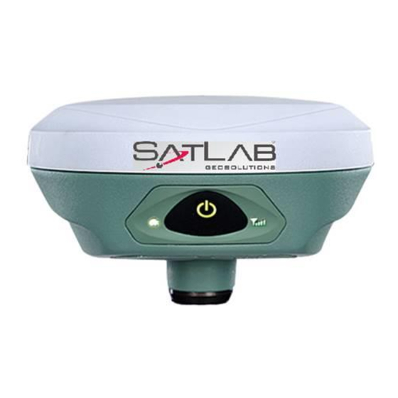
Receiver appearance SL800 consists of three parts: the antenna cover, the lower housing and the control panel. Figure 2-1 Receiver appearance The Control panel contains a power button and three LED lights, respectively; satellite indicator LED, power LED (red and green), communication status LED (red and green). - Page 9 The bottom of the receiver has a 5 pin lemo interface, USB interface and protective plugs. The 5 pin lemo interface is used for the connection of the receiver with an external data link and/or an external power supply. The USB interface is for external equipment connection, firmware upgrade, static data download, and for charging the receiver battery.
-
Page 10: Power Key Function
Power key function Power key function: power on/off, work mode switch, power query, automatic setting of the base station, and resetting of the motherboard. Function Action Boot Press power button for 1 second, all lights come on and receiver boots. Shut Down Long press power button for 3 seconds, all lights flash twice, release the button to turn... -
Page 11: Led Indicator Function
LED indicator function Receiver has three LED lights, respectively; satellite light, power lights (red and green), signal lights (red and greens). LED Indicator Description Power light (Green) Solid Battery fully charged Power light (Yellow) Solid Battery good Solid Battery > 6% charge Flash Battery <5% charge Flash... -
Page 12: Battery Installation
Battery Installation Figure 2-4 Battery compartment (1) Press cover catch up to open battery compartment. (2) Align the battery electrode with the electrode of the battery compartment and gently push it until it is flush with the battery compartment. (3) Reinstall the battery cover to complete the battery installation. Working mode setting Double-click the power button to enter the work mode switch. -
Page 13: Static Measurement
Static measurement (1) Set up the receiver over the station to be measured with the ‘measure plate’ fixed to bottom of the receiver. (2) Measure the instrument height from the ground point to the upper surface of the measure plate. (3) Record the station name, instrument number, instrument high, date and start observation time. -
Page 14: Static Data Download
When the receiver storage space is less than 10MB, the signal red light flash, and will stop recording data; the existing data files will not be overwritten. Static data download Receiver file management uses U disk storage, plug and play, direct drag and drop download. To ensure data security using U disk memory, only static data download is possible and file deletion of the data is not possible. -
Page 15: Chapter 3
Chapter 3 Operation of SL800 using SurvCE This section describes: ■ Running SurvCE ■ GPS Rover configuration ■ Monitor/Skyplot page... -
Page 16: Quick Start Guide For Survce
Quick Start Guide for SurvCE This section provides a Quick Start guide for operation of the SL800 with SurvCE. The intention is to instruct the user regards connecting to the SL800 and to establish a Network connection to provide correction data. For a detailed description of the use of SurvCE please refer to the Carlson SurvCE User Manual. - Page 17 The program will open with option to continue the ‘Last Job’ or ‘Select New/Existing’ job. You then have the option to connect to the ‘last device’ or continue without connection. If this latter option is selected the program will move to the main Menu page.
-
Page 18: Gps Rover Configuration Menu
Figure 3-3 SurvCE ‘GPS Rover’ Menu page GPS Rover Configuration Menu Select ‘GPS Rover’ to allow configuration of the receiver. In this menu there are four tabs as shown below. Current tab enables selection of Manufacturer and Model of the receiver. -
Page 19: Comms Tab
Figure 3-4 Receiver selection tab Comms tab enables Bluetooth connection to the receiver. Click on ‘Find Device’ then select the corresponding serial number. Next, select ‘Device PIN’ and type 1234. Click on the Bluetooth icon to connect to the receiver. Figure 3-5 Bluetooth connection configuration... - Page 20 Figure 3-6 Bluetooth connection Figure 3-7 Bluetooth connection...
-
Page 21: Receiver Tab
Receiver tab is used to set the antenna height and will automatically add the offset from ARP (Antenna Reference Point) to the Antenna phase centre. Figure 3-8 Antenna Height setting page The Advanced button enables the configuration of NMEA output via the serial port and also configure satellite constellations. -
Page 22: Rtk Tab
RTK tab enables configuration to connect to a Network to stream correction data. The only ‘Device’ option for the SL800 is ‘Data Collector Internet’ as the data link is provided via the controller GSM modem or WiFi link. Network connection options are NTRIP and intRTK. Configuration of the Network login parameters is performed by clicking on the hammer and spanner icon. - Page 23 Figure 3-10 Example NTRIP connection settings...
-
Page 24: Monitor/Skyplot Tab
Monitor/Skyplot tab provides status information regards the receiver position and satellite tracking This tab information. Figure 3-11 SurvCE Monitor/Skyplot Menu page... - Page 25 Figure 3-12 Monitor Quality page Figure 3-13 Monitor Skyplot page...
-
Page 26: Chapter 4
Chapter 4 Technical Specification This section describes: ■ GNSS configuration ■ System configuration ■ Built-in communication ■ Control panel ■ External interface ■ Electrical characteristics ■ Physical characteristics ■ Environment... -
Page 27: Gnss Specification
GNSS Specification Channel Count 555 Channels Signal Tracking GPS L1 C/A, L1C, L2C, L2P, L5 GLONASS L1 C/A, L2 C/A, L2P, L3, L5 BeiDou B1, B2, B3 Galileo E1, E5 AltBOC, E5a, E5b, E6 NavIC (IRNSS) L5 SBAS L1, L5 QZSS L1 C/A, L1C, L2C, L5, L6 L-Band up to 5 channels Horizontal Position Accuracy (RMS) - Page 28 Time to First Fix Cold start < 40 s (typical) Hot start < 19 s (typical) Signal Reacquisition < 0.5 s (typical) < 1.0 s (typical) System Configuration ◇ Operating system: intelligent real-time system ◇ Start time: 1 second ◇ Data storage: built-in 8GB memory Built-in communication ◇...
- Page 29 Electrical characteristics ◇ Battery: high-capacity lithium battery 6300mAh / 3.7V, removable, continuous working hours more than 8 hours ◇ Voltage: USB interface: DC 4.2-5.5V / 2A; small five-core interface: DC 6-28V / 2A ◇ Power consumption: 3.2W Physical characteristics ◇ Size: 127.5mm × 57mm ◇...
-
Page 30: Chapter 5
Chapter 5 Interface and main accessories This section describes: ■ Small five-core lemo interface ■ Lithium battery ■ Adapter ■ USB data cable ■ Measure reference parts... -
Page 31: Small Five-Core Lemo Interface
Small five-core lemo interface The five-core lemo connector is used for the connection of the receiver with an external data link and/or an external power supply. Figure 5-1 small five-core lemo interface Lemo 5 pin interface Description: facing the bottom of the receiver counter clockwise 1 to GND 2 to GND 3 power into Vin... -
Page 32: Receiver Lithium Battery
3 hair". Receiver lithium battery SL800 has as standard a lithium battery (6300mAh / 3.7V), model BLP-6300S. Technical process and performance is better than nickel-cadmium or nickel-metal hydride batteries as it has no memory effect and when not in use has slow self-discharge function. -
Page 33: Power Adapter
Power Adapter Use the standard power adapter (PSAI10R-050Q) for charging. Although the receiver has over- temperature protection, in order to ensure safety, charging should be performed in the 0 ℃ ~ 40 ℃ ambient temperature range. Figure 5-4 Adapter USB data cable Use the USB data cable to connect the computer for the host firmware upgrade and static data download. -
Page 34: Height Measuring Plate
Figure 5-5 USB data cable Height measuring plate The height measuring plate is used to measure the height of the instrument. Measurement is taken from the ground point to the top surface of the measure plate. Figure 5-6 Nominal phase centre... -
Page 35: Schedule 1 - Factory Default Parameters
Figure 5-7 Height measure plate Schedule 1 - Factory default parameters Default System parameters for Mobile station Working mode RTK Message Format RTCM (3.2) Satellite elevation cut-off angle 10 GPS satellite enabled BDS satellite enabled GLONASS enabled Static sampling interval 5 seconds Static elevation cut-off angle of 10 degrees Schedule 2 Key Parts Information Motherboard Novatel OEM729 555 channel...
Need help?
Do you have a question about the SL800 and is the answer not in the manual?
Questions and answers