
Related Manuals for SatLab SL900 GNSS RTK


Summary of Contents for SatLab SL900 GNSS RTK
- Page 1 SL900 GNSS RTK System Getting Started SL900 GNSS RTK SystemGetting Started Satlab GeosolutionsAll Rights Reserved...
- Page 2 Preface Manual Revision Revision Date Revision Level Description Aug., 2018 SL900 GNSS RTK System User Guide...
-
Page 3: Preface
SL900 GNSS RTK System Getting Started Preface Introduction Welcome to the SATLAB SL900 receiver. This introduction describes how touse this product. Experience Requirement In order to help you use SATLAB series products better, SATLAB suggests you carefully read instructions. unfamiliar with products,... - Page 4 The pictures in the operating instructions arefor reference only. In case of non-conformity with products, the products shall prevail. Technology and Service If you have any technical issues, please call SATLAB technology department for help, we will answer your question. Relevant Information You can obtain this introduction by: 1.
-
Page 5: Table Of Contents
SL900 GNSS RTK System Getting Started Contents Preface ........................III Overview ........................1 1.1 Foreword ....................... 2 1.2 Features ......................3 1.3 Use and precautions ..................4 Product Introduction ....................5 2.1 Overall appearance ..................6 2.1.1 Control panel ..................6 2.1.2 Upper cover................... - Page 6 Contents 3.2 Static survey ....................15 3.2.1 Steps of static survey ................16 3.2.2 Static data storage ................17 3.2.3 Static data download ................18 3.3 Dynamic RTK survey ...................19 3.4 Firmware upgrade ..................22 3.5 Tilt survey ....................22 3.5.1 Tilt calibration ..................23 3.5.2 Calibration verification ................30 3.5.3 Tilt survey procedure ................30 3.6 Radio channel settings ................30 Technical Prameters ....................32...
- Page 7 SL900 GNSS RTK System Getting Started 5.2 Mini USB ......................41 5.2.1 Mini USB interface ................41 5.2.2 Mini USB data cable ................42 5.3 Antenna interface ..................42 5.3.1 Antenna interface .................42 5.3.2 Antenna ....................43 5.4 Benchmark ....................43 5.5 Battery & charger ..................44 5.5.1 Battery installation and unload ..............44...
-
Page 9: Overview
SL900 GNSS RTK System Getting Started CHAPTER Overview This chapter contains: Foreword Features Use and precautions... -
Page 10: Foreword
Overview 1.1 Foreword A new generation of miniaturized SL900 GNSS RTK system, condensing our ultimate professional pursuit, with enthusiast performance configuration, using magnesium alloy structure, supporting tilt measurement, using Wi-Fi wireless connection, control distance up to 100 meters; built-in transceiver integrated radio, working distance farther. In addition,... -
Page 11: Features
SL900 GNSS RTK System Getting Started 1.2 Features 1. New design, magnesium alloy structure, smaller size, lighter weight and higher quality; 2. Linux operating system, more powerful and more reliable; 3.The transceiver UHF radio enables switchable working modes between base and rover;... -
Page 12: Use And Precautions
Overview 1.3Use and precautions The SL900 receiver is designed with chemical and impact resistance, but precision instruments require careful use and maintenance. Notice: The receiver must be within the specified temperature range when used and stored. Detailed requirements, please refer to Chapter 4: Technical →... -
Page 13: Product Introduction
SL900 GNSS RTK System Getting Started CHAPTER Product Introduction This chapter contains: Overall appearance... -
Page 14: Overall Appearance
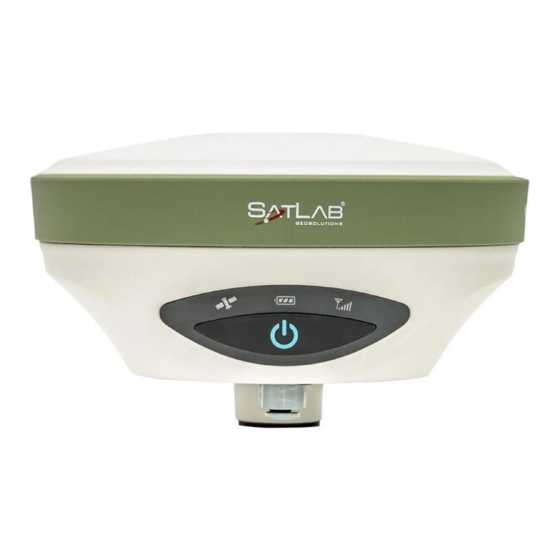
Product Introduction 2.1 Overall appearance The product appearance is divided into three parts, including the upper cover, bottom cover and control panel. Upper cover Control panel Bottom cover Figure 2-1-1Front 2.1.1Control panel In the middle of the mainframe is the control panel which contains a power button and three indicator lamps. -
Page 15: Upper Cover
SL900 GNSS RTK System Getting Started Figure 2-1-2 Control Panel Satellite Lamp (single green lamp) Power Lamp (bi-color lamp of red and green) Status Lamp (bi-color lamp of red and green) Power key functions: power on,power off, mode switching, mode switching confirmation, status inquiry, automatic base station setting, forced shutdown, reset motherboard, etc. -
Page 16: Bottom Cover
Product Introduction Anti-wear Buffer Figure 2-1-3Upper cove 2.1.3Bottom cover... - Page 17 SL900 GNSS RTK System Getting Started Figure 2-1-4 Bottom Cover 1.Battery compartment cover 2. Connection screw 3. Five-pin socket 4.Antenna 5.USBsocket 6. Speaker 7.SD cardslot 8. Nano SIM card slot 9. Spring contacts - Connection screw: It is used to fasten the instrument to base or centering rod.
- Page 18 Product Introduction - GPRS / UHF built-in radio antenna interface: GPRS antenna when using the network, UHF built-in radio antenna when using the radio. - Five-pin socket: for external data linking and external power supply. - Connection screw: for fixing the instrumentto the base or a pole. Notice: 1.
-
Page 19: Basic Operation
SL900 GNSS RTK System Getting Started CHAPTER Basic Operation This chapter contains: Button & LED Static survey Dynamic RTK survey Firmware upgrade Tilt survey Radio channel settings... -
Page 20: Button & Led
Basic Operation 3.1 Button & LED SL900 adopts optimized and simplified design,button operation with control panel is more convenient and concise Figure 3-1-1 Button & LED 1-Power key 2-Satellite lamp 3-Power lamp 4-Differential signal lamp 3.1.1 Button function Table 3-1-1ButtonFunction Description Function Description Power-on... -
Page 21: Host Status Query
SL900 GNSS RTK System Getting Started click will switch to another work mode Work mode Single click to confirm the current work mode State query See attached In power on status, long press power button for more than 6s when Reset main board voice prompts the second dingdong, then release it . -
Page 22: Led Indicator Lamp
Basic Operation 3.1.3 LED indicator lamp Indicators are displayed in different settings; See Appendix 3: Control Panel Indicators. Table 3-1-3LEDfunction description Item Status Description In normal voltage Power light Long-term lighting Battery>7.6V (yellow) External power supply>12.6V In normal voltage: 7.1V<battery<7.6V Always on 11V<external power supply<12.6V Power lamp... -
Page 23: Static Survey
SL900 GNSS RTK System Getting Started (green) Slow flash Lose satellites and try re-track 1. mother board error resulting in no data output while resetting receiver 2. mother board error resulting in no data output while in static mode Reset main board or static collecting... -
Page 24: Steps Of Staticsurvey
Basic Operation 3.2.1 Steps of staticsurvey 1. Set up receiver on a control point, centering and leveling strictly. 2. Measure the height of receiver for three times, on condition that the difference of each measuring is less than 3mm and the final height of the receiver should be the average height. Instrument height should be measured from control point to the upper of measurement bench marker. The radius of the SL900 receiver benchmarkis 0.130m, and the phase center is 0.1018m high. -
Page 25: Static Data Storage
SL900 GNSS RTK System Getting Started 6. Download and process data. Notice: Don’t move the tri-brach or change the collecting set while the receiver is collecting data. 3.2.2Static datastorage The collected GNSS static data is stored in the static drive letter in the 16GB storage of the SL900 receiver. -
Page 26: Static Data Download
Basic Operation 3.2.3Static data download SL900 receiver file management using U disk storage, plug-and-play, direct drag-and-drop download, do not need to download the program. SL900 receiver can only download static data by using U disk mode, can not write to the SL900 receiver. SL900 receiver can download data by U-disk, use Mini USB cable when downloading. -
Page 27: Dynamicrtk Survey
SL900 GNSS RTK System Getting Started Notice: Static files in removable disks can not be deleted directly, we can use controller software to conduct. 3.3DynamicRTK survey The dynamic RTK measurement can be based on the propagation mode of the differential signal for the radio mode (internal radio, external radio, external station) and network mode. - Page 28 Basic Operation Figure 3-3-1 Bluetooth Connect Figure 3-3-2 Device Connect 3. Parameter sittings of base The base station parameters include setting the target height, base station coordinates, working mode and corresponding parameters, message format, elevation angle, and so on. After completing the relevant parameter editing, click the Settings button in the upper right corner, and the software prompts Setup Successful! Figure 3-3-3 Receiver SettingsFigure 3-3-4 Choice of Radio...
- Page 29 SL900 GNSS RTK System Getting Started Figure 3-3-5 Other Settings 4. Rover settings The mobile station receiver is fixed on the telescopic centering pole, and the handbook is fixed on the handbook carrier. The mobile station settings are basically the same as the base station, mainly including the working mode setting, the altitude angle, and the like.
-
Page 30: Firmware Upgrade
Basic Operation 3.4 Firmware upgrade You can Upgrade firmware by USB cable manually. Steps to upgrading the firmwareby USB cable: 1. Turn on the receiver, connect the receiver and computer with the cable attached. It will show the update driveafter clicking thecomputer; 2.Copy the firmware(download from our official website or get it from the technical team) to the update drive.Disconnect the computer and receiver, and restart the receiver;... -
Page 31: Tilt Calibration
SL900 GNSS RTK System Getting Started 3.5.1Tilt calibration The whole tilt calibration has three steps: - Orientation sensor calibration; - Electronic bubble calibration; - Magnetic calibration. The order of 1 and 2 steps can be reversed, but must be performed before step 3 Notice: 1. - Page 32 Basic Operation Figure 3-5-1 Start Calibration Click Start to begin calibration, the calibration of the orientation sensor needs to be calibrated according to the demo. Figure 3-5-2WarningFigure 3-5-3 Rotate The Device - Rotate at an average speed, approximately 7 seconds for a cycle. - Clockwise rotate about 45 degrees, repeat step a, you need a total of 8 cycles at least.
- Page 33 SL900 GNSS RTK System Getting Started Success from the device, that means calibration is finished. Conversely, prompting failure - do calibration again. Figure 3-5-4 Calibrated Successfully 2. Electronic bubble calibration - Connect to the receiver with tilt survey function. In Additional Settings, click Electronic Bubble Calibration to enter the program.
- Page 34 Basic Operation - When the device had been perfectly levelled up, click Start for calibration, then click OK. Figure 3-5-6 Warning - When success is prompted, the electronic bubble and horizontal bubble of base will be centered at the same time. Figure 3-5-7 Calibration Success...
- Page 35 SL900 GNSS RTK System Getting Started - Calibration is finished. Notice: It is recommended to calibrate the device every 30 days, but the calibration cycle can be adjusted. - Auto collection. When the auto mode is set as Bubble Is centered the software will collect the points automatically when the electronic bubble is centered.
- Page 36 Basic Operation Figure 3-5-10 Tilt Survey And Bubble Precision 3. Magnetic calibration This step can be done only after the calibration of electronic bubble and orientation. Additional Settings→ click Magnetic calibration to enter calibration interface. Figure 3-5-11Start Calibration...
- Page 37 SL900 GNSS RTK System Getting Started Click Start to start calibration, magnetic calibration needs calibration in horizontal position. Figure 3-5-12 Warning Figure 3-5-13 Calibrating Interface Keep the device on horizontal and rotate it clockwise a week, slowly and evenly around the vertical axis.
-
Page 38: Calibration Verification
Basic Operation 3.5.2Calibration verification In order to make sure accuracy is not strongly interfered with by the environment and procedure, verification is necessary before starting the tilt survey. Put the device at 30 degree tilt approximately, on the pole, and rotate it slowly clockwise for a week. - Page 39 SL900 GNSS RTK System Getting Started 450MHz-470MHz and provides 116 communication channels for users to choose. User uses the handbook software for channel setting Notice: Once the base station's transmitting station channel is modified, the mobile station also needs to modify to the corresponding channel, otherwise the differential signal cannot be received.
-
Page 40: Technical Prameters
Technical Prameters CHAPTER Technical Prameters This chapter contains: Technical parameters... -
Page 41: Technical Parameters
SL900 GNSS RTK System Getting Started 4.1 Technical parameters Table 4-1-1 Technical Parameters Configuration Detailed indicators System: multi-star system core (OEM729) Channels:555 BeiDou: B1, B2, B3 GPS: L1C/A, L1C,L2C, L2P, L5 GLONASS : L1C/A, L2C, L2PL3,L5 Satellite signals tracked GALILEO... - Page 42 Technical Prameters Starting Time Horizontal: 8mm+1ppmRMS Single baseline Vertical: 15mm +1ppm RMS Horizontal: 8mm+ 0.5ppmRMS Network RTK Vertical: 15mm + 0.5ppm RMS Horizontal: 2.5mm +0.1ppm RMS High-precisionstatic Vertical: 3.5mm + 0.4ppm RMS Horizontal: 2.5mm +0.5ppm RMS Accuracy and Static and fast static Reliability Vertical: 5mm + 0.5ppm RMS Horizontal: 25cm RMS...
- Page 43 SL900 GNSS RTK System Getting Started Frequency: 403MHz-473MHz(4FSK,GMSK) Transmission rate:19.2kbps/9.6kbps adjustable Button Singlebutton User Interface LEDLamp Satellite lamp, signal lamp,power light Voice broadcast Report the working status of the receiver Intelligent voice Function self-test Voice broadcast receiver self-test results 2×5000mAh lithium-ion rechargeable and...
- Page 44 Technical Prameters Storagetemperature -40℃ ~ 85℃ Note: [1] Hardware ready for L3 and L5 [2] E1bc and E6bc support only [3] Hardware ready for L5 [4]Measurement accuracy and reliability are affected by many factors, including satellite geometry, satellite number, observation time, satellite ephemeris, ionospheric conditions, and multipath.
-
Page 45: Accessories And Interfaces
SL900 GNSS RTK System Getting Started CHAPTER Accessories and Interfaces This chapter contains: 5-pin socket Mini USB Antennainterface Benchmark Battery& charger... -
Page 46: Five-Pin Socket
Accessories and Interfaces This chapter describes the appearance and use of the main interfaces and accessories of the SL900. The following devices do not mean that all users who have purchased the SL900 have these devices. The configuration will vary according to user requirements. The specific configuration is based on the outbound order at the time of purchase. - Page 47 SL900 GNSS RTK System Getting Started 1.Five-pin data cable: It is also known as COM which used to connect the host and external radio to transmit differential data. Table 5-1-1 Description of Five-pin Signal Five-pin Signal Ground GND Ground GND...
-
Page 48: Five-Pin Data Cable
Accessories and Interfaces 5.1.2 Five-pin data cable Figure 5-1-3Five-pin Data Cable 1.Five-pin data cable: to connect the host and external radio to transmit differential data. 2. Five-pin plug: A five-pin interface for connecting the receiver to an external radio. Figure 5-1-4Five-pin Plug Notice: 1. -
Page 49: Mini Usb
SL900 GNSS RTK System Getting Started the plug with effort. It shall not rotate the plug. 3. After using the cable, it shall place the cable in the place difficult for extrusion, in order to prevent damaging the plug. When installing the... -
Page 50: Mini Usb Data Cable
Accessories and Interfaces 5.2.2 Mini USB data cable Standard USB interface Mini USB interface Figure 5-2-2Mini USB data cable The Mini USB cable has a standard USB interface on one end and a Mini USB interface on the other end; it is used for connection between the host and external devices for data transmission. 5.3 Antenna interface 5.3.1 Antenna interface Figure 5-3-1Antenna Interface... -
Page 51: Antenna
SL900 GNSS RTK System Getting Started 5.3.2 Antenna There isone standard radio antenna and one 4G antenna, you can select the appropriate antenna according to theoperation mode. The UHF radio antenna is used in the internal UHF mode, and the external 4G antenna is used in the internal GSM mode. -
Page 52: Battery & Charger
Accessories and Interfaces Figure 5-4-1Benchmark 5.5Battery & charger 5.5.1 Battery installation and unload 1. Installation Lightly press the battery cover and press down, and the battery cover can be lifted up. Figure 5-5-1Battery Cover Put the on the bottom of the battery marked with Open to the battery compartment, and into the battery rack. - Page 53 SL900 GNSS RTK System Getting Started Figure 5-5-2Battery Bay Install the battery by gently pressing and pushing it toward the end marked Close. Figure 5-5-3 Installed Battery 2. Unload Gently press and push in the direction marked Open, pour out the battery and complete the...
-
Page 54: Battery And Charger Model
Accessories and Interfaces 5.5.2 Battery and charger model Table 5-5-1Battery and charger model Name Model Lithium-ion battery BL-5000 Battery charger CL-8410 5.5.3 Power supply mode Table 5-5-2Power Supply Mode Lithium battery Power supply mode Power 5-pin socket external power supply Supply Power supply range 6V min and 28V max... -
Page 55: Cautions For Charging
SL900 GNSS RTK System Getting Started as 2W internal transceiver transmitting station. 2. In order to extend the life of the battery, please charge the battery as soon as possible within 24 hours after the battery is exhausted, otherwise the battery life will be shortened. -
Page 56: Operation Of Charging
Accessories and Interfaces 5.5.5 Operation of charging 1. Put the on the bottom of the battery marked with Open to the battery compartment, and into the battery rack. 2. Install the battery by gently pressing and pushing it toward the end marked Close. 3.
Need help?
Do you have a question about the SL900 GNSS RTK and is the answer not in the manual?
Questions and answers