
Related Manuals for SatLab SL600


Summary of Contents for SatLab SL600
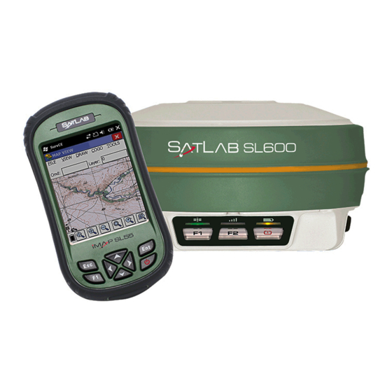
- Page 1 SL600 GNSS Receiver User’s Manual Satlab SL600 User’s Guide, Rev. 1.5, December 2014. www.satlabgps.com ©2014 Satlab Geosolution AB. All rights reserved.
- Page 2 ©2014 Satlab Geosolution AB. All rights reserved. All product and brand names mentioned in this publication are trademarks of their respective holders. Satlab SL600 User’s Guide, Rev. 1.5, December 2014. Limited Warranty Supplier hereby warrants solely to the end user customer of the Products, subject to the exclusions and procedures set forth...
- Page 3 www.satlabgps.com...
- Page 4 Equipped with two high capacity hot-swappable Li-Ion battery packs, that together provide up to 24 hours of uninterrupted operation. In addition to its 1GB of internal memory, SL600 is equipped with a Micro SD card slot for storing large files like long static observations in high precision applications.
-
Page 6: Table Of Contents
2.4.1. Communication Ports 2.4.1.1. COM1 2.4.1.2. COM2 2.4.1.3. Bluetooth 3. Operation 3.1. Introduction 3.2. Software Tools 3.2.1. Satlab GNSS Management Software 3.2.2. Satlab UHF Radio Management Software 3.3. Field Operations 3.3.1. Network Rover 3.3.2. UHF Base/Rover 3.3.3. Static Data Collection www.satlabgps.com... - Page 7 Table of Contents 4. Satlab SurvCE Guide 4.1. Creating A Job 4.2. Network Rover Settings 4.3. UHF Base Settings 4.4. UHF Rover Settings 4.5. Recording Points 4.6. Offset 4.7. Auto Recording 4.8. Stake Out 4.9. Download/Upload Points 4.10. DXF-DWG Export/Import 4.11.
-
Page 8: Introduction
2. Receiver Physical Appearance 2.1. Introduction In the default configuration, Satlab SL600 is available as a complete kit including Satlab SL600 receiver, its transport case and corresponding accessories which are given in the following section Note: Items in the standard configuration may differ depending on the application or geographical conditions. -
Page 9: Items Of Transport Case
2. Receiver Physical Appearance 2.2.1. Items of Transport Case Satlab SL600 standard kit consists of following items inside the transport case Item Description Picture Quantity SL600 GNSS Receiver 1 pc SL55 Field Controller 1 pc 1 pc Pole Holder 1 pc... -
Page 10: Housing
2. Receiver Physical Appearance 2.3. Housing Satlab SL600 housing is made of General Electric Xenoy 5220U polymer resin to withstand severe and harsh environment conditions. Housing consists of two main parts, namely top part, covering the GNSS antenna and bottom part, accomodating electronics, ports and compartments. -
Page 11: Bottom Housing
PLASTIC PROTECTIVE PLUGS ON TO PROTECT CONNECTORS FROM BEING DAMAGED. COMMUNICATION MODULE According to different requirements, SL600 receiver can be equipped with UHF radio options with different parameters. Consult your local dealer to define the correct UHF Radio Modem Options. -
Page 12: Battery
2. Receiver Physical Appearance 2.3.1.1. Battery Satlab SL600 uses two hot swappable Li-Ion batteries 7.4V, 5000 mAh. When the receiver is powered on, it activates one of the batteries. It activates to second one in case of any power loss in the first battery without interrupting the operation. - Page 13 Unlock symbol to Lock symbol. Figure 2.6 Battery cover Batteries are partially charged before being shipped. Depending on the storage period, they can be fully discharged. Therefore, batteries need to be fully charged before being used in Satlab SL600. Figure 2.7 Battery Charger. www.satlabgps.com...
-
Page 14: Sim Card
Green: Charging has been completed. 2.3.1.2. SIM Card SatLab SL600 is equipped with a 3.5G multi band cellular modem providing mobile data connection to perform internet based RTK. In order to operate the internal modem, a SIM card with internet access is necessary. - Page 15 2. Receiver Physical Appearance To insert/remove SIM card: 1. Turn off the device. 2. Remove battery cover by pushing the slide button towards the “open lock” symbol. The cover will partially eject. 3. Remove the battery by pushing it towards the “open” direction if there is any. 4.
-
Page 16: Memory Card
2. Receiver Physical Appearance 2.3.1.3. Memory Card In addition to its 1GB internal storage SL600 is equipped with a microSD card slot. SatLab SL600 supports all microSD cards with up to 64 GB capacity which provides months of data storage for static observations. -
Page 17: Control Panel
Power LED. The three function buttons allows setting up different SL600 receiver modes and functions. Figure 2.11 Satlab SL600 front panel. SL600 has three function, test and control keys in the GNSS receiver. These are often used to reset the measure without using any GNSS control unit. ON/OFF Power Key:... - Page 18 Operation Mode: Satlab SL600 receiver can be set to Static mode to record raw data, RTK base station to stream corrections to a UHF Radio or an internet RTK Server, or RTK Rover station by UHF or Internet.
-
Page 19: Communication
Table 2.3 LED Indicators 2.4. Communication 2.4.1. Communication Ports Satlab SL600 is equipped with Bluetooth and two sealed ports called COM1 and COM2 for external power supply and communications with external computer terminals. Figure 2.x Communication ports www.satlabgps.com... -
Page 20: Com1
2. Receiver Physical Appearance 2.4.1.1. COM1 COM1 or communication port number 1 is an industry level sealed push-pull 8 pin connector providing RS232 serial, USB communications as well as power supply. COM1 1 RXD Data input 2 USB D- 3 USB D+ 4 USB V+ 5 Vin Power input 6 Cable Detection... -
Page 21: Com2
2. Receiver Physical Appearance Figure 2.x Inserting COM1 Y cable to receiver. 2.4.1.2. COM2 COM2 or communication port number 2 is an industry level sealed push-pull 5 pin connector providing RS232 serial and power supply. COM2 1 GND earth 2 GND earth 3 Vin Power Input 4 RXD Data input 5 TXD Data output... -
Page 22: Bluetooth
2. Receiver Physical Appearance 2.4.1.3. Bluetooth The main communication medium in SL600 is Bluetooth which is being used to communicate with handheld computer in the daily usage. Bluetooth connection uses RS232 communication port in COM1. In other words, RS232 communication port in COM1 is assigned to be communicated by Bluetooth once it is bonded. - Page 23 2. Receiver Physical Appearance 3- If necessary, set COM ports to paired connection under Bluetooth Settings: 4- Then Satlab SL600 can be communicated as if it was connected through serial cable. www.satlabgps.com...
-
Page 24: Operation
Second section explains the field work considerations and also operational steps. 3.2. Software Tools Satlab SL600 can be accessed and set up by three different software tools in addition to field software called Satlab SurvCE. For Satlab SurvCE operations, please refer to chapter 4. - Page 25 NTRIP can be entered here. For the parameters please refer to your local NTRIP and GSM provider. Figure 3.2 Net tab Radio: Radio tab in the tool is for advanced diagnostics. For changing radio parameters, please refer to Satlab UHF Radio Management Software explained in the next section. www.satlabgps.com...
- Page 26 3. Operation Static: In the static tab, raw data collection parameters can be set. Moreover, raw data files can also be listed. Downloading raw data files can be done by connecting to PC via USB and copying from the unit in file explorer.
- Page 27 3. Operation Figure 3.4 Basic Tab Advanced: In this section, Voice can be enabled or disabled, GSM band can be set, GSM signal can be diagnosed and NMEA data can be output. Figure 3.5 Advanced Tab www.satlabgps.com...
-
Page 28: Satlab Uhf Radio Management Software
Communication with Satlab SL600 can be done by using RS232 Y cable with serial connection to a PC. Software requires a simple RS232 connection without any flow control. Any Windows operating system from Windows XP should work as long as there is a RS232 serial driver. - Page 29 3. Operation Satlab SL600 consists of - System Board/Computer, controlling the whole operation by setting traffic rules among communication ports, GNSS Receiver and Telemetry Medium. - GNSS Receiver, tracking satellites, outputting raw observation data and running RTK algorithm - Telemetry Medium, UHF Radio or 3G modem, transferring corrections from/to GNSS Receiver Telemetry Medium is set to either UHF Radio or 3G modem by Telemetry Mode.
-
Page 30: Field Operations
2.5G (EDGE) to 4G should be fine to meet the bandwidth requirements. However it requires a continuous connection to provide corrections at 1Hz. It is advisable to use both internal modem in SL600 and modem in SL55 controller with different GSM operators in case of any coverage problems. -
Page 31: Satlab Survce Guide
4. Satlab SurvCE Guide 4.1. Creating A Job Double click on the SATLAB SurvCE icon on the controller unit and execute the program. The program helps you by opening the business manager. There are two options: • Continue Last Job •... - Page 32 4. Satlab SurvCE Guide After giving a name to the job, the software will automatically be redirected to the Job Settings menu. Choose the coordinate system from the System tab in the Job Settings menu, which is composed of Format, Options, Stake, New Job and System tabs.
- Page 33 4. Satlab SurvCE Guide Time Stamp Each Point option should be selected in the Options tab. As long as this option is not selected, the date-time information that belongs to measurements will not be stored. After the selection click on Okay and job settings will be loaded.
-
Page 34: Network Rover Settings
4. Satlab SurvCE Guide 4.2. Network Rover Settings GPS Rover is selected in the Equip menu. Under the GPS Rover menu you will find these tabs: Current, Comms, Receiver and RTK. In the Current tab select: Manufacturer: SATLAB Model: SL600... - Page 35 PIN, enter 1234 as PIN code and click on After setting up the Bluetooth connection, go to the Receiver tab. The settings that are under this tab; Select SLGSL600_ V1antenna (with pre-defined offset for Satlab) Antenna Height: measure your antenna height and enter Elevation Mask: 10...
- Page 36 4. Satlab SurvCE Guide Finally, move to the tab RTK. This section is extremely important for initializing a survey. For a receiver that will be utilized as Mobile Rover CORS; Device: Select Internal GSM Modem and click Settings. Select a profile to connect the SIM card in the device to the Internet.
- Page 37 4. Satlab SurvCE Guide After a while, a pop-up window lists available bases for CORS solution. Example shows SWEPOS network with selected base station Goteborg. This table shows which format and type of message is used by this base station as well as the geographic co-ordinates of the base station.
-
Page 38: Uhf Base Settings
4. Satlab SurvCE Guide 4.3. UHF Base Settings GNSS Receiver UHF Antenna Extension Pole Tribrach and Adapter Tripod www.satlabgps.com... - Page 39 4. Satlab SurvCE Guide GPS Base is selected in the Equip menu. There are 4 tabs under GPS Base menu. All settings are done through these tabs. In the Current tab select; Manufacturer: SATLAB Model: SL600 In the Comms tab;...
- Page 40 4. Satlab SurvCE Guide After setting up the Bluetooth connection, go to the Receiver tab. The settings that are under this tab Select SLGSL600_V1 antenna (with pre-defined offset for SATLAB) Antenna Height: measure your antenna height and enter Elevation Mask: 10 Position Rate: 5 Hz In addition, select the type of antenna height: Vertical or Slant.
- Page 41 4. Satlab SurvCE Guide Coordinate may be inserted manually directly or read from a file. Also if the point is registered in the control unit, it can be selected from the list via the Point List button or selected from map screen.
-
Page 42: Uhf Rover Settings
4. Satlab SurvCE Guide 4.4. UHF Rover Settings GNSS Receiver UHF Antenna Controller Controller Bracket Telescopic Pole www.satlabgps.com... - Page 43 4. Satlab SurvCE Guide GPS Rover is selected in the Equip menu. There are 4 tabs under GPS Rover menu. All settings are done through these tabs. In the Current tab select; Manufacturer: SATLAB Model: SL600 In the Comms tab; Bluetooth is selected and when no...
- Page 44 4. Satlab SurvCE Guide After setting up the Bluetooth connection, go to the Receiver tab. The settings that are under this tab Select SLGSL600_ V1antenna (with pre-defined offset for SATLAB) Antenna Height: measure your antenna height and enter Elevation mask: 10...
-
Page 45: Recording Points
4. Satlab SurvCE Guide 4.5. Recording Points In the Survey menu, Store Points is selected. Survey with Avarage Offset Store Points Settings-Reading Solution Status Configuration Satellite Observation Scale Bar Number of Satellites Coordinates Horizontal-Vertical Accuracy Screen Settings Find Zoom In... - Page 46 4. Satlab SurvCE Guide Before initiating the survey with storing points, enter a point name in the Pt: line. HT: connotes the height of the antenna which you enter according to your antenna height. The functions of the buttons you see on the screen are as follows: Measures once and saves automatically.
- Page 47 4. Satlab SurvCE Guide 4.6. Offset Offset button in STORE PTS screen. Click on the In the Method tab, select Intersect or 2 Point method. 2 Point method is described as an example. Come to a stop on the point number 1 and read via Point 1 Read.
-
Page 48: Auto Recording
4. Satlab SurvCE Guide 4.7. Auto Recording Select the Auto by Interval in the Survey menu. Select necessary settings depending on the required point storing intervals. Write the Starting Pt ID, where the automatic point storing will be started and click on Okay. -
Page 49: Stake Out
4. Satlab SurvCE Guide 4.8. Stake Out Select Stake Points button in the Survey menu. A window opens where you define points to be staked out: A point that should be staked out can be selected in three ways; 1. Manual entry of coordinates 2. - Page 50 4. Satlab SurvCE Guide Using graphic screen you can select points for staking out directly from the map. In either way, after selecting a point, the software shows the selected point number and coordinates on the screen for checking. Click on Okay to start the stake out procedure.
- Page 51 4. Satlab SurvCE Guide As you approach, the scale of the screen automatically changes and gets more sensitive. Tolerance circles appear around the point. According to the required precision of stake out, the point is found. Satellite Information Solution Type...
- Page 52 4. Satlab SurvCE Guide There is also an alternative screen view for stake out. In this view, base map does not appear. Only the point to be staked out and the current receiver position is shown. In order to move to text view screen, click the...
-
Page 53: Download/Upload Points
4. Satlab SurvCE Guide 4.9. Download/Upload Points In order to import points for staking out or export surveyed points, first of all the connection between the controller and the computer must be established. The users with Windows XP as operating system shall install Microsoft ActiveSync, while the users who have Windows Vista and Windows 7 as operating system shall install the Microsoft Mobile Device Center. - Page 54 4. Satlab SurvCE Guide Select the desired type and format of points to be imported. Select a file which is shown in a directory under the NandFlash folder and click Okay. In the example on the left, Coordinates.txt file from Storage Card directory has been selected.
- Page 55 4. Satlab SurvCE Guide Select destination file: the job into which the points will be Okay. You obtain then information loaded and click about number of imported points and the import is completed successfully. If you want to check if the points are loaded correct or not, click on the Points button under File menu.
-
Page 56: Dxf-Dwg Export/Import
4. Satlab SurvCE Guide 4.10. DXF-DWG Export/Import Click on the Import/Export button in the File menu. In the pop- up window, select Export Ascii File. Select File Type: User Defined and make your choice about the coordinate order, delimiters, range of points etc. -
Page 57: Specifications
• 3 LED Indicator Panel Communications • Internal 3.5G UMTS/HSDPA GSM Modem • Internal Dijital UHF Modem Options - ADLF1 : 2 Watts, SATLAB Protocol - XDL : 2 Watts, Trimtalk, Satel, TrimMark, Transparent Protocol Power • DC 6-28 V Input •... -
Page 58: Ngs Antenna Parameters
5. Specifications 5.2. NGS Antenna Parameters SLGSL600 _V1+NONE 99,44MM MMI TO NORTH Azimuthal Orientation 55,00MM Display Panel Reference surface for NGS vertical offset measurements Ø 182,00MM Ø 184,00MM www.satlabgps.com... -
Page 59: Trouble Shooting
Firmware Failure terminal tool. Firmware Failure Upgrade firmware or consult to Local Dealer In order to connect to SL600 by Bluetooth, a Pin Code Bluetooth Connection fails pin code of 1234 is required. Without pin code, bonding Bluetooth is not possible. - Page 60 6. Trouble Shooting Symptom Possible Reason Solution Make sure that both base and rover stations are High error in position calculation Coordinate system setup set by the same coordinate reference and the same settings. Make sure that SIM pin is disabled and internet SIM Card Ntrip connection fails service is available.
Need help?
Do you have a question about the SL600 and is the answer not in the manual?
Questions and answers