
Related Manuals for SatLab SL700 GNSS RTK


Summary of Contents for SatLab SL700 GNSS RTK
- Page 1 SL700 GNSS RTK System Getting Started SL700 GNSS RTK SystemGetting Started Satlab GeosolutionsAll Rights Reserved...
- Page 2 Preface Manual Revision Revision Date Revision Level Description Aug., 2018 SL700 GNSS RTK System User Guide...
-
Page 3: Preface
SL700 GNSS RTK System Getting Started Preface Introduction Welcome to the SATLAB SL700 receiver. This introduction describes how touse this product. Experience Requirement In order to help you use SATLAB series products better, SATLAB suggests you carefully read instructions. unfamiliar with products,... - Page 4 The pictures in the operating instructions arefor reference only. In case of non-conformity with products, the products shall prevail. Technology and Service If you have any technical issues, please call SATLAB technology department for help, we will answer your question. Relevant Information You can obtain this introduction by: 1.
-
Page 5: Table Of Contents
SL700 GNSS RTK System Getting Started Contents Preface ........................III Overview ........................1 1.1 Foreword ....................... 2 1.2 Features ......................3 1.3 Use and precautions ..................3 Product Introduction ....................5 2.1 Overall appearance ..................6 2.1.1 Upper cover................... 6 2.1.2 Bottom cover .................. - Page 6 Contents 2.4 Dynamic RTK survey ...................15 2.5 Firmware upgrade ..................17 Technical Parameters ....................19 3.1 Technical parameters ..................20 Accessories and Interfaces ..................24 4.1 SIM card installation..................25 4.2 Data cable ....................26 4.3 Antenna ......................28 4.4 Benchmark ....................28 4.5 Battery & charger ..................29 4.5.1 Battery installation and unload ..............29 4.5.2 Battery and charger model ..............31 4.5.3 Power supply mode ................31...
-
Page 7: Overview
SL700 GNSS RTK System Getting Started CHAPTER Overview This chapter contains: Foreword Features Use and precautions... -
Page 8: Foreword
Overview 1.1 Foreword A new generation of miniaturized SL700 GNSS RTK system, condensing our ultimate professional pursuit, with enthusiast performance configuration, using magnesium alloy structure, supporting tilt measurement, using Wi-Fi wireless connection, control distance up to 100 meters; built-in transceiver integrated radio, working distance farther. In addition,... -
Page 9: Features
SL700 GNSS RTK System Getting Started 1.2 Features 1. New design, magnesium alloy structure, smaller size, lighter weight and higher quality; 2. Linux operating system, more powerful and more reliable; 3.The transceiver UHF radio enables switchable working modes between base and rover;... - Page 10 Overview Notice: The receiver must be within the specified temperature range when used and stored. Detailed requirements, please refer to Chapter 3: Technical Parameters. In order to ensure the continuous tracking observation of the satellite and the quality of the satellite signal, it is required that the space above the station should be as wide as possible, and there should be no obstacles above the 15°...
-
Page 11: Product Introduction
SL700 GNSS RTK System Getting Started CHAPTER Product Introduction This chapter contains: Overall appearance Button & indicator lamp Static survey Dynamic RTK survey Firmware upgrade... -
Page 12: Overall Appearance
Product Introduction 2.1 Overall appearance The product appearance is divided into three parts, including the upper cover, bottom cover and control panel. Upper cover Control panel Bottom cover Figure 2-1-1Front 2.1.1 Upper cover Anti-wear Buffer Figure 2-1-2Upper Cover Anti-wear Buffer: Wear prevention points can enable the host to avoid scratching. -
Page 13: Bottom Cover
SL700 GNSS RTK System Getting Started 2.1.2Bottom cover Figure 2-1-3 Bottom Cover 1.Five-pin socket&Protective plug2. Host label3. Connection screw 4. Speaker5. Battery compartment and cover6. USBsocketand protective plug 7. Network/radio antenna interface and protective plug - Connection screw: For fixing the instrumentto the base or a pole - Protective plug: Used for dustproof and waterproof sockets. -
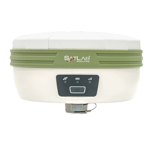
Page 14: Button &Indicator Lamp
Product Introduction data. It can also be used as the USB to serial port,in special working modes (you need to install the driver). - Speaker: Timely operate the instrument and broadcast the status with voice - Battery compartment: Used to place the battery. - Battery cover: Cover the battery cover to protect it from dust and water. - Page 15 SL700 GNSS RTK System Getting Started every double click will switch to another work mode. Work mode Single click to confirm the current work mode. State query See appendix. In power on status, long press power button for more than 6s when Reset main board voice prompts the second dingdong, then release it.
-
Page 16: Indicator Lamp
Product Introduction 2.2.2Indicator lamp Table 2-2-3Description of Indicator LampFunction Item Status Description In normal voltage Power light Long-term lighting (yellow) Battery remaining≥60% Always on Battery remaining :10%~60% Power lamp (red) Slow flash Low voltage: batteryremaining<10% No GSM connection Signal lamp Always on GSM module connect to server successfully (green)... -
Page 17: Static Survey
SL700 GNSS RTK System Getting Started lamp In temporary static mode, flash according to the Flash (red) sampling interval. Reset main board or static collecting Anomaly flashof 3 lamps error(Insufficient storage space ) 2.3Static survey SL700 receiver can be used for static measurement. It is set by double-clicking the power key to enter the mode switching, every double-clicking, switching one mode of operation. -
Page 18: Static Data Storage
Product Introduction 0.1018m high. 95.45mm (phase center) Benchmark 130mm Figure 2-3-1 Benchmark Sketch 3. Record point name, receiver S/N, receiver height, beginning time. 4. Press power button to power on and double click power button to set static collecting mode; then single click power button to confirm it. -
Page 19: Static Data Download
SL700 GNSS RTK System Getting Started rinex. The log folder stores log information. The data format stored in the gnss folder is *.gns; The data format stored in the rinex folder is a standard RINEX format data file. You can connect to your computer using a randomly configured USB cable and use the USB disk to copy static data to your computer. - Page 20 Product Introduction Connect the receiver with computer by the Mini USB data cable. After the connection, a static code appears in the computer, then copy the collected static files out byopening the disk. Figure 2-3-3 Static Drive After downloading, steps of editing the point name and antenna height are: 1.
-
Page 21: Dynamicrtk Survey
SL700 GNSS RTK System Getting Started 2.4DynamicRTK survey The dynamic RTK measurement can be based on the propagation mode of the differential signal for the radio mode (internal radio, external radio, external station) and network mode. 1. Erection of instrument The receiver is mounted on a stable known point or unknown point. - Page 22 Product Introduction 3. Parameter sittings of base station The base station parameters include setting the target height, base station coordinates, working mode and corresponding parameters, message format, elevation angle, and so on. After completing the relevant parameter editing, click the Settings button in the upper right corner, and the software prompts Setup Successful! Figure 2-4-3 Receiver Settings Figure 2-4-4 Choice of Radio...
-
Page 23: Firmware Upgrade
SL700 GNSS RTK System Getting Started 4. Rover settings The mobile station receiver is fixed on the telescopic centering pole, and the handbook is fixed on the handbook carrier. The mobile station settings are basically the same as the base station, mainly including the working mode setting, the altitude angle, and the like. - Page 24 Product Introduction 2.Copy the firmware(download from our official website or get it from the technical team) to the update drive.Disconnect the computer and receiver, and restart the receiver; Figure 2-5-1Update drive...
-
Page 25: Technical Parameters
SL700 GNSS RTK System Getting Started CHAPTER Technical Parameters This chapter contains: Technical parameters... -
Page 26: Technical Parameters
Technical Parameters 3.1 Technical parameters Table 3-1-1 Technical Parameters Configuration Detailed indicators System: multi-star system core (OEM729) Channels: 555 BDS: B1, B2, B3 GPS: L1C/A, L1C,L2C, L2P, L5 GLONASS : L1C/A, L2C, L2P,L3,L5 Satellite signals tracked GALILEO : E1,E5AltBOC,E5a,E5b,E6 simultaneously SBAS: L1, L5 GNSS QZASS: L1 C/A, L1C, L2C, L5, L6... - Page 27 SL700 GNSS RTK System Getting Started Horizontal: 8mm+1ppmRMS Single baseline Vertical: 15mm +1ppm RMS Horizontal: 8mm+ 0.5ppmRMS Network RTK Vertical: 15mm + 0.5ppm RMS Horizontal: 2.5mm +0.1ppm RMS High-precisionstatic Vertical: 3.5mm + 0.4ppm RMS Horizontal: 2.5mm +0.5ppm RMS Accuracy and...
- Page 28 Technical Parameters Transmission rate:19.2kbps/9.6kbps adjustable Button Singlebutton User Interface IndicatorLamp Satellite lamp, signal lamp,power light Voice broadcast Report the working status of the receiver Intelligent voice Function self-test Voice broadcast receiver self-test results 2×5000mAh lithium-ion rechargeable and Internal battery removable battery RTK rover(Cellular) ≥10 hours 6-28VDCexternalpowerinputwith Externalpower...
- Page 29 SL700 GNSS RTK System Getting Started Note: [1] Hardware ready for L3 and L5 [2] E1bc and E6bc support only [3] Hardware ready for L5 [4]Measurement accuracy and reliability are affected by many factors, including satellite geometry, satellite number, observation time, satellite ephemeris, ionospheric conditions, and multipath.
-
Page 30: Accessories And Interfaces
Accessories and Interfaces CHAPTER Accessories and Interfaces This chapter contains: SIM card installation Data cable Antenna Benchmark Battery& charger... -
Page 31: Sim Card Installation
SL700 GNSS RTK System Getting Started 4.1SIM card installation SL700 receiver supports the SIM card. Table 4-1-1 SIM Card Description GPRS(ZHD/VRS) SIM card To implement an RTK work using the SL700 receiver, you need to prepare a SIM card and open the data communication service. -
Page 32: Data Cable
Accessories and Interfaces Figure 4-1-2 Installation 4. The entire SIM card is placed in the card slot. The installation is completed. Notice: The receiver must be powered off before installing the card! If the SIM card is installed in the power on state, the receiver will not be able to detect the SIM card, and the setting of working mode is invalid! 4.2Data cable... - Page 33 SL700 GNSS RTK System Getting Started 2.Five-pin data cable (DG-3): to connect the host and external radio to transmit differential data. Figure 4-2-2Five-pin Data Cable Figure 4-2-3Five-pin Plug Notice: 1. When connecting various plugs of receiver, it shall align the red point in line joint at the red point in receiver socket, or it will damage the receiver socket and plugs of various lines.
-
Page 34: Antenna
Accessories and Interfaces 3. After using the cable, it should be arranged in a place that is not easy to be squeezed to prevent damage to the plug. When installing the differential antenna, make sure that the hand is rotating the fixed nut at the bottom of the differential antenna. -
Page 35: Battery & Charger
SL700 GNSS RTK System Getting Started 95.45mm (phase center) Benchmark 130mm Figure 4-4-1Benchmark 4.5Battery & charger 4.5.1 Battery installation and unload 1. Installation Press the battery cover button gently and press down. The battery cover can be lifted upwards. The battery cover and battery are removed as shown in the figure. To the right is unlocked and... - Page 36 Accessories and Interfaces Figure 4-5-1Unload Put the on the bottom of the battery marked with Open to the battery compartment, and into the battery rack. Figure 4-5-2 Installed Battery 2. Unload Gently press and push in the direction marked Open, pour out the battery and complete the battery unloading.
-
Page 37: Battery And Charger Model
SL700 GNSS RTK System Getting Started 4.5.2 Battery and charger model Table 4-5-1Battery and Charger Model Name Model Lithium-ion battery BL-5000 Battery charger CL-8410 4.5.3 Power supply mode Table 4-5-2Power Supply Mode Lithium battery; Power supply mode Power 5-pin socket external power supply... -
Page 38: Cautions For Charging
Accessories and Interfaces 2. In order to extend the life of the battery, please charge the battery as soon as possible within 24 hours after the battery is exhausted, otherwise the battery life will be shortened. 3. If the battery is not used for a long time, in order to prolong its service time, please charge the battery once per month. -
Page 39: Operation Of Charging
SL700 GNSS RTK System Getting Started 4.5.5 Operation of charging Close Charging signal lamp Power lamp Figure 5-5-5 Method of Charging 1. Put the on the bottom of the battery marked with Open to the battery compartment, and into the battery rack.
Need help?
Do you have a question about the SL700 GNSS RTK and is the answer not in the manual?
Questions and answers