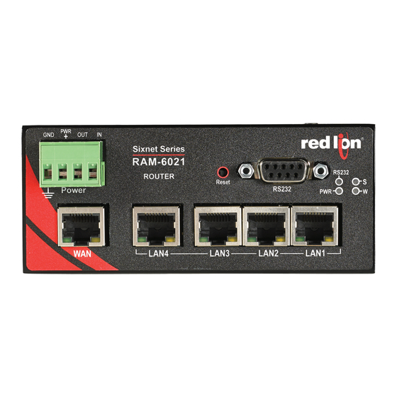
red lion RAM-6021 Software User's Manual
Secure industrial wired router
Hide thumbs
Also See for RAM-6021:
- Hardware manual (36 pages) ,
- Hardware and installation manual (15 pages) ,
- Quick start manual (2 pages)

Related Manuals for red lion RAM-6021


Summary of Contents for red lion RAM-6021
- Page 1 RAM-6021 Wired Router Software User Guide Version 1.0 Software Version 4.15 November 2013 www.redlion.net...
-
Page 2: Table Of Contents
Connect PC to Red Lion Router........ - Page 3 Chapter 3 Red Lion Support ........111 Chapter 4 Software Licensing Terms and Conditions.
-
Page 4: Chapter 1 Accessing The Web User Interface
Connect PC to Red Lion Router Chapter 1 Accessing the Web User Interface Connect PC to Red Lion Router Connect a CAT‐5 or CAT‐6 Ethernet cable between the local PC and the Red Lion router’s Ethernet Port(s). Note: If the Ethernet port’s green LED is lit, this indicates that the connection is running at 100Mb speed. If the Ethernet port’s green LED is not lit, this indicates that the connection is running at 10Mb speed. The yellow LED indicates the “link” status of the connection. Yellow steady= Link established. Yellow flashing = Data packets are being transferred. RAM-6021 Wired Router... -
Page 5: Setup Pc Ip Address
Setup PC IP Address Setup PC IP Address 1.2.1 Open the Control Panel • Click on Start and browse the “Control Panel” menu item. The Control Panel should look similar to the following: RAM-6021 Wired Router... -
Page 6: Access Network And Settings
Setup PC IP Address 1.2.2 Access Network and Settings • Click on the link to access network and Internet settings • XP ‐ “Network and Internet Connections” • Vista/Windows 7 “Network and Internet” • The displays should be similar to the following: 1.2.3 Access Network Connection Settings • Click on the link to access network connection settings. • XP ‐ “Network Connections” • Vista/Windows 7 ‐ “Network and Sharing Center” • The display should look similar to the following: RAM-6021 Wired Router... -
Page 7: Access Local Area Connection
Setup PC IP Address 1.2.4 Access Local Area Connection • Click on the link to access the local area connection. • XP ‐ “Local Area Connection” icon • Vista/Windows 7 ‐ “View Status” next to Local Area Connection • The display should look similar to the following: 1.2.5 Open Properties • Click on “Properties” button (Vista/Windows 7 will display a popup window asking to confirm the operation). • Click on the “Continue” button. The display should look similar to the following: RAM-6021 Wired Router... -
Page 8: Access Internet Protocol Properties
Setup PC IP Address 1.2.6 Access Internet Protocol Properties • Click on the Internet Protocol to highlight. • XP ‐ “Internet Protocol (TCP/IP)” • Vista/Windows7 ‐ “Internet Protocol Version 4 (TCP/IPv4)” • Click on the “Properties” button. The display should look similar to the following: METHOD 1: PC to Ethernet on RAM‐6021 • Select “Use the following IP address” and fill in the blank fields with the information below: •IP address:192.168.0.2 •Subnet mask:255.255.255.0 •Default gateway:192.168.0.1 •Preferred DNS:192.168.0.1 • Click “OK”. • The previous screen will appear. • Click “OK”. RAM-6021 Wired Router... - Page 9 Setup PC IP Address METHOD 2: PC to LAN (ETH1) (RAM‐6021) • Select “Use the following IP address” and fill in the blank fields with the information below: •IP address:192.168.1.2 •Subnet mask:255.255.255.0 •Default gateway:192.168.1.1 •Preferred DNS:192.168.1.1 • Click “OK”. • The previous screen will appear. • Click “OK”. Verify that you are connected to the RAM‐6021 router. • Open a Command Prompt window on your laptop. • XP Start Run, type in cmd and press the ENTER key. RAM-6021 Wired Router...
- Page 10 Setup PC IP Address • Vista/Windows 7 Start Search window just above the Start icon, type in cmd, wait for Vista/Windows 7 to locate the program, click on the cmd program if finds. Verify connectivity to the router by running a “ping” to the IP Address of the Ethernet port you are connected to. METHOD 1: PC to Ethernet on RAM‐6021 Type in ping 192.168.0.1 and then press the ENTER key The display should look similar to the following: METHOD 2: PC to ETH1 (LAN) Type in ping 192.168.1.1 and the press the ENTER key The display should look similar to the following: This shows the connection is up and functioning. RAM-6021 Wired Router...
-
Page 11: Access Red Lion Web Server
Access Red Lion Web Server Access Red Lion Web Server • Open a web browser and enter the following in the address bar: METHOD 1 (WAN/ETH0): http://192.168.0.1:10000/ METHOD 2 (LAN/ETH1): http://192.168.1.1:10000/ • You will receive a login pop‐up screen. 1.3.1 Red Lion Router Login Instructions • For the User Name, enter: admin (all lowercase) • For Password, enter the last six digits of the serial number, located on the product label (all lowercase) Upon successfully logging in, the following screen will appear: Note: The following information can be used for all series of router, even if screen shots indicate other models. Some models may have reduced options. At this point, you are connected to the Red Lion router and can configure it to meet your needs. RAM-6021 Wired Router... -
Page 12: Chapter 2 Web User Interface
Chapter 2 Web User Interface Web User Interface Introduction 2.1.1 Organization The Red Lion Web UI is comprised of six major sections. (Click on a link to get an in‐depth description of each topic) • Status: The Status tab presents information on the router. This tab is organized into five (5) sections: Summary, Network, Diagnostics, Syslog and Gather Stats. • Admin: The Admin Tab is used to configure how the Red Lion router is accessed, update the firmware, reset the system defaults, set the system time and reboot the router remotely. This tab is organized into six (6) sections: Access Settings, System Time, Firmware Update, Configuration Manager, Package Installation and Factory Defaults. • Network: The Network Tab is used to configure settings that connect the router to external interfaces. The Net‐ work tab is organized into six (6) major categories: Interfaces, Firewall, Tunnelling, DNS Settings, Static Routes, TCP Global Settings. • Services: The Services tab is used to configure the various features of the Red Lion router. These services include DHCP Server, DHCP Relay, SNProxy Settings, SixView Manager, SSH/TELNET Server, SNMP Agent, Ping Alive and Serial IP. • Automation: Selecting this tab directs you to the ‘Classic View’ presentation to view and set automation parame‐ ters. Note: This section has not yet been updated to the new interface and selecting Classic view will direct you to the previous version of the Admin Utility. Any defaults you define will be respected. • Advanced: The Advanced Tab is used to configure the advanced features of the Red Lion router, which include Out‐ of‐Band Management, VRRP, Expert Mode, Classic View and About. All tabs are described further in the manual as well as functionality of each dialog window. RAM-6021 Wired Router... -
Page 13: Status Tab
Status Tab Status Tab The Status Tab allows you to review the state of the router functions, such as network connections, interfaces, system pro‐ cesses, services running, and system information. It also allows review of the syslog, update history, and under diagnostic tools, permits testing connectivity through the use of ‘ping’ and ‘traceroute’. 2.2.1 Summary This option will return the user to the System Summary (home) page. On this page, the system information and physical interface status are easily viewed. RAM-6021 Wired Router... - Page 14 Status Tab 2.2.1.1 EZ Config Wizard The EZ Config Wizard is used to setup your Ethernet IP without having to navigate through multiple dialog windows. The EZ Config Wizard is situated on the Summary page and accessed by clicking on the Blue EZ Config Wizard button. • Click on the EZ Config Wizard button. The Eth0 Settings dialog window will open: Enable eth0 Interface: Select Yes to enable the interface or No to disable it. If you select No, the fields below the “Enable eth0 Interface” will disappear. Obtain Network Addresses via DHCP: Select Yes to allow the interface to obtain address information via a DHCP server. The device will obtain its IP address, netmask and remote gateway as the default route. It can also, optionally, obtain DNS server address via DHCP. Select No to prevent the interface from obtaining address information via a DHCP servers. You will be required to enter the IP address, netmask and remote gateway addresses. DNS information can be pro‐ vided by navigating to the Network>DNS Settings menu. Enter IP Address (Required): Enter the desired interface IP address. This field is only available when the “Obtain Net‐ work Addresses via DHCP” is set to No. The IP address identifies a device on a TCP/IP network. Every device on a network must have a unique address. The range of valid addresses for a given network is determined by the value of the Netmask. Some addresses are reserved for special uses such as network and broadcast. For example, if a netmask is 255.255.255.0 and the IP address RAM-6021 Wired Router...
- Page 15 Status Tab assigned to the device is 192.168.1.1 through 192.168.1.254 as 192.168.1.0 is the value reserved for the broadcast address. Recommended Setting: This address should have been provided by your Network Administrator. It must be an address valid for the network described by the value contained in the Enter Subnet Mask field and must not conflict with any other device on the target network. Enter Subnet Mask (Required): Enter the desired Netmask for the interface. This field is only available when “Obtain Network Addresses via DHCP” has been set to No. Recommended Setting: Your network administrator should be able to provide an appropriate value. This value determines the valid range of IP addresses allowed in the “Enter IP Address” field. Enter Remote Gateway: Enter the IP Address for the gateway device. This field is required if “Use Remote Gateway as Default Route” is set to Yes. A gateway is a device (typically a router) used to gain access to another network. For example, if a device is attached to a LAN whose network address is 192.168.1.0 with a netmask of 255.255.255.0, then it can communicate directly with any other device on that network with a range of addresses of 192.168.1.1 through 192.168.1.254 (with 192.168.1.255 reserved for broadcast). An address outside of that range is on a different network which would need to be accessed indirectly through a router. That router would be the gateway to the network on which the remote target device resides. In order to communicate with it, it would mean sending and receiving via the gateway device. This also requires either defining a static route (defined through the Network>Static Routes menu) via that gateway or making it the default route by setting “Use Remote Gateway as Default Route” to Yes. Recommended Setting: Your network administrator should be able to provide an appropriate value. The address must be one within the valid range for the network. • Once the desired settings have been entered in the Eth0 Settings dialog window, click on the Next button and the following dialog window will appear: • Enter the required settings for your Eth1. (See documentation for Eth0 Settings). Once the desired settings have been entered, click on the Finish button and a recommendation dialog window will appear. RAM-6021 Wired Router...
-
Page 16: Network
Status Tab • Click on Revert, Save or Apply ( ). see explanation of each setting in dialog window above 2.2.2 Network The Network menu contains the following sub‐menus: Arp Cache, Firewall Rules, Interfaces, Routing Tables and Socket Statuses. 2.2.2.1 ARP Cache The “ARP Cache” is a table which stores mappings between Data Link Layer (OSI Layer 2) addresses and Network Layer (OSI Layer 3) addresses. This important information shows what connections are established to the router. When you click on the ARP Cache menu item, the following dialog window will appear. RAM-6021 Wired Router... - Page 17 Status Tab 2.2.2.2 Firewall Rules The “Firewall Rules” menu item displays a complete listing of the rules used within the firewall for the Red Lion router. If you are familiar with Linux and IPTables, then this will be of great use. Scroll through the list of rules to review the entire IPTABLES listing. This information is used to track traffic being allowed and traffic being denied access to and through the Red Lion router. 2.2.2.3 Interfaces The “Interfaces” menu item has three sections. Summary, Details and Multicast. RAM-6021 Wired Router...
- Page 18 Status Tab The “Summary” table displays a brief description of the interfaces of the Red Lion router. The “Details” table displays a system specific description of the interfaces on the Red Lion router. The “Multicast” table displays the current multicast settings for various interfaces. 2.2.2.4 Routing Tables The “Routing Tables” dialog window contains both the Standard System Routing Table and the Policy Routing Table. The “Standard System Routing Table” displays the current routes for the Red Lion router and the static routes that have been configured for the router. The “Policy Routing Table” displays information on the policy rules, the route tables for each individual interface and the general routes for the Red Lion router. 2.2.2.5 Socket Statuses Sockets are end‐points to communication over the Internet. Much like PBX phone systems, where the IP address is the phone number and the port is the extension. Every paired (connected) socket has a source IP/port and a destination IP/ port. There are three tables in the Socket Statuses dialog window: “TCP Only”, “Conn Track” and “Socket Statuses All” The “TCP Only” table displays the sockets that are connection‐oriented (Also known as “stream sockets”). “Conn Track” is a connection tracker that displays more thorough information about the current socket connections. Con‐ nection tracking allows the kernel to keep track of all logical network connections or sessions, and thereby relate all of the packets which may make up that connection. NAT relies on this information to translate all related packets in the same way, and IPTABLES can use this information to act as a stateful firewall. RAM-6021 Wired Router...
-
Page 19: Diagnostics
Status Tab The “Socket Statuses All” table displays the sockets that are considered connection‐oriented and connectionless (also known as “datagram sockets”). 2.2.3 Diagnostics The Diagnostics menu is sub‐sectioned into Ping, Socket Test and Traceroute submenus. These are useful in troubleshoot‐ ing connectivity of the Red Lion router to the Internet or the Network the router is connected to. 2.2.3.1 Ping The Ping menu item allows you to input an address either as an IP Address or a URL for testing the destination availability. RAM-6021 Wired Router... - Page 20 Status Tab Host/IP Address field: Type in the IP Address or URL you wish to Ping. It is recommended you start with a locally accessible IP address to confirm communication to an interface’s local subnet. Then proceed to addresses on distant networks. Your local default gateway is a good test, and this IP can be found in the your routing table. Also, a com‐ monly available internet server available to test against is 4.2.2.2 Source Interface: The Source Interface offers the option of using different interfaces to send the Ping through. This is useful if you have a VPN Tunnel in place. Testing the connection through the VPN Tunnel is required to verify connec‐ tivity through the tunnel. Choose the interface that the VPN Tunnel has listed for the Local Subnet end‐point, i.e. if the Left Subnet is 10.100.100.0/24 and eth1 has 10.100.100.1 as its IP Address, then choose Source Interface eth1. Specify a Host/IP Address at the head‐end to Ping through the tunnel. • Click on the Ping button to see the result. 2.2.3.2 Socket Test The Socket Test menu item will allow you the “Telnet” to desired destination IP and Port addresses to verify the socket availability. RAM-6021 Wired Router...
- Page 21 Status Tab Host/IP Address field: Type in the IP Address or URL you wish to Telnet. Destination Port field: Enter the Destination IP Address of the server to which you would like to connect. • Click on the Test button at the bottom of the dialog window to proceed with the TCP socket test to verify socket availability. 2.2.3.3 Traceroute The Traceroute menu item will allow you to watch the route taken through the Internet to the specified IP Address or URL. Host/IP Address field: Type in the IP Address or URL you wish to trace. It is recommended to start with a locally acces‐ sible IP address to confirm communications to an interface’s local subnet. Then proceed to addresses on distant net‐ works. You local default gateway is a good test, and this IP can be found in your routing table. A commonly available internet server available to test against is 4.2.2.2. Source Interface field: Select the source interface. Choosing “Unspecified” will let the system choose the first inter‐ face found with a route to the destination. The Source Interface offers the option of using different interfaces to send the trace through. This is useful should you have a VPN Tunnel in place and testing the connection through the VPN Tunnel is required to verify connectivity through the tunnel. Choose the interface that the VPN Tunnel has listed for the Local Subnet end‐point, i.e. if the Left Subnet is 10.100.100.0/24 and eth1 has 10.100.100.1 as its IP Address, then choose Source Interface eth1. Specify a host IP Address at the head‐end to ping through the tunnel. • Click on the Trace button at the bottom of the dialog window and a table describing the Trace Route results will appear in the dialog window. RAM-6021 Wired Router...
-
Page 22: Syslog
Status Tab 2.2.4 Syslog The Syslog window will display the current log into the syslog of the Red Lion router. Customize your search by configuring the following fields: Filter String (optional): Enter a filter string in the space provided. Only lines containing the filter value(s) will be dis‐ played via a GREP (Global Regular Expression Parser) style filter mechanism. Auto Update: Select YES to enable automatic updating of the log file display. The update interval can be selected using the Select Update Interval option provided in the field below the Auto Update one. Manual updating is disabled while auto update is in effect. The current filter and maximum lines to be displayed will be used. Number of lines to display: Select the number of lines to be displayed from one of the choices in the drop‐down list provided. Update Interval: Select how often you wish the update interval to be used when auto update is enabled. • Click on the download button and the following window will appear prompting whether to save or open the file: RAM-6021 Wired Router... -
Page 23: Gather Stats
Status Tab 2.2.5 Gather Stats Include IPSEC (Barf) Output: Select YES to include all IPSEC (Internet Protocol Security) Include GWLNX Log Files: Select YES to include all GWLNX related logs. Choose YES if you are running GWLNX for pro‐ tocol conversion. This will increase the size of the resulting .zip file. Include All Configuration Files: Select YES to include ALL GWLNX protocol conversion related files. This included GWLNX application as well and will considerably increase the size of your resulting zip file. Note: Only choose YES for this option if directed by the Technical Support Staff. Include GWLNX Files: Select YES to include all GWLNX configuration files. The recommended setting for this option is YES. Include All Network Files: Select YES to include all networking related configuration files. If using “gaterconfigs” to clone a unit, note that this option will cause the network interfaces (Including static IP addresses) to be cloned as well. Note: If performing a gatherconfigs for review by technical support staff, please choose YES for this option. • To create the download files for the Stats and/or Configs, click on the Download Stats and Download Configs but‐ tons. The following pop‐up will show up asking whether you want to open or save the file. RAM-6021 Wired Router... -
Page 24: Admin Tab
Admin Tab Admin Tab The Admin Tab is where you configure web access methods, set passwords, update firmware, manage configurations and set factory defaults. 2.3.1 Access Settings The “Access Settings” menu item allows you to change how the unit’s Web UI is accessed, either by HTTP or HTTPS. You can also change the passwords used to access the Web User Interface. For security purposes, it is recommended that the admin password be changed according to your internal policies. • Click on the “Access Settings” menu item and the following window will appear. RAM-6021 Wired Router... -
Page 25: System Time
Admin Tab To change the access method: Click on the pull down menu next to “Web Access Method” and select the method you would like to use to access the Web UI. You do not need to enter the password in order to change the access method. Note: The HTTP method can result in better performance and faster page load time; however, it is less secure than the HTTPS method, which uses data encryption to provide a secure connection. If you are not changing the password, click on the “APPLY” button for changes to take effect. To change the password: Enter the new password in the “New Password” field. Note: For a secure password, choose one that is at least six char‐ acters long, which is not a common word and comprised of a mixture of upper and lower case characters and num‐ bers. Re‐enter the new password in the “Confirm New Password” field. In the “Confirm Admin Password”, which appears at the bottom of the dialog window once you enter a new password, enter the current password. • Click on the “Save” button for changes to be saved without activating the interface, the “Apply” button will save your settings and apply them immediately. To revert to the previous settings, click on the “Revert” button. 2.3.2 System Time The System Time menu item is used to configure the time zone on the Red Lion router to correspond to your location. • Click on the System Time menu time and the following window will appear. RAM-6021 Wired Router... -
Page 26: Firmware Update
Admin Tab Time Zone: Select the time zone corresponding to your geographical location by choosing one of the values available on the drop down list provided. To configure the date and time for your Red Lion router there are three options: Option 1: Sync to NTP Server: Select Yes to enable synchronizing the system clock to an NTP server. Option 2 ‐ Manual Configuration: Current Date (MM/DD/YYYY) (Required): Set the Sync to NTP Server field to No and enter the Current Date using the shown format. Current Time (HH:MM:SS) (Required): Set the Sync to NTP Server field to No and enter the Current Time using the shown format. Note: The Hour field in on the 24‐hour time clock, range 00‐24. This page verifies that the month, day, year, hour, min‐ ute and seconds conform to expected inputs. For example, month range from 01‐12, days range from 01‐31 (checks for limit according to month, i.e. January has 31 days, February has 28 or 29 depending on year, etc.) Option 3: Use Local System Time: Set the Sync to NTP Server field to No and click on the Use Local System Time button. The local time as referenced from your browser is used to populate the settings. • Click on the Apply button to save your settings and apply them immediately. To revert to the previously saved defaults, click on the “Revert” button. 2.3.3 Firmware Update The Firmware Update menu item is used to upgrade the firmware of the Red Lion router. RAM-6021 Wired Router... - Page 27 Admin Tab • Click on the Firmware Update menu item and the following window will appear: To upgrade the firmware of the Red Lion router: Boot Image File: Select the file that will perform the Kernel update. Root Image File: Select the file that will perform the system update. Preserve current configuration: Select YES to cause the device to save its current configuration and restore it after the firmware image is installed. Note: Select the “Boot File System” type and “Browse” to open “boot” file image first and click on the “Upload” button for uploading the boot file. Then once this step is completed, select “Root File System” type and “Browse” to open “root” file image and click on “Upload” button for uploading the root file. • Click on the “Install” button. Note: This procedure could take anywhere from 6‐10 minutes to complete. WARNING: It is important that the power to the unit is not interrupted as this could cause the unit to become corrupt and require shipment back to the factory to correct. 2.3.3.1 Configuration Manager The Configuration Manager menu item saves a copy of the current system configuration, i.e., Export. This is useful when a confirmed good configuration is operational. A backup can be exported for use should the configuration become corrupt or re‐configured in error. RAM-6021 Wired Router...
- Page 28 Admin Tab • Click on the Configuration Manager menu item and the following window will appear: Export Web UI Master Configuration File: To save a copy of the Red Lion router configuration, click on the “Export” but‐ ton. The pop‐up window below asking you to save or open the file will appear. Select the desired option. Note: Please note the directory where the file was saved in order to retrieve it when needed to put the file back onto the Red Lion router. Import Web UI Master Configuration File: Set your importing defaults for the configuration file. Import File Handling: Select Replace to completely replace the device configuration file with your import. Select merge if you are importing a snippet of the main configuration. Save Import file without applying changes: If you want to save the new configuration without immediately applying it, simply select YES. To apply the settings, you will need to visit the configuration page for each supported sub‐system and click its Apply button. This is unusual, but useful for when you are importing a configuration from one unit to another and need to make additional settings before applying them. RAM-6021 Wired Router...
- Page 29 Admin Tab Import Configuration File: Click on the Select File button, and the dialog window below will appear. • Browse to the directory where the config.xml.txt file is located. • Select the config.xml.txt file and click on the Open button to populate the Browse window. If needed, you can change the file or remove it from the field by clicking the appropriate button • Click on the Import button. When import is complete, a table will appear at the bottom of the dialog window list‐ ing the modified files. 2.3.3.2 Package Installation The Package Installation feature allows you to upload and install patches from Red Lion. RAM-6021 Wired Router...
- Page 30 Admin Tab • Click on the Package Installation menu item and the following dialog window will appear: • In the Package File field, click the Select File button, and the following dialog window appear: • Browse to the directory where the patch is located. • Select the filename to select the file. Note: Be sure to use only genuine Red Lion provided packages in the form of filename.zip. • Click on the Open button to populate the Package File field and click on the Install button. When install is com‐ plete, a table will appear at the bottom of the dialog window listing the modified files. RAM-6021 Wired Router...
- Page 31 Admin Tab 2.3.3.3 Factory Defaults The Factory Defaults menu item allows you to restore the configuration back to factory default settings. • Click on the Factory Defaults menu item and the following window will appear: Restore Factory Default: Click on the Restore button to restore the factory default settings. A warning will appear, read through the information and click OK. The restore may take 2‐5 minutes. Reboot System: Click on the Reboot button to reboot the device. A warning will appear, read through the information and click OK. The reboot may take 2‐5 minutes. RAM-6021 Wired Router...
-
Page 32: Network Tab
Network Tab Network Tab The Network Tab configures aspects of the Red Lion router affecting the networking functionality of the unit. From here you can configure the Ethernet Interfaces, Static Routes, TCP Keep‐Alives and VPN Tunnel configuration. 2.4.1 Interfaces The Interfaces menu allows the administrator to configure the Ethernet ports of Red Lion routers to meet their needs. Interfaces available may include eth0 (WAN), eth1 (LAN), and USB. These will only be present if your hardware supports these interfaces. These ports are ‘auto‐sensing’, allowing for greater flexibility. 2.4.1.1 eth0 and eth1 (Internet Interfaces) The configuration of the Ethernet ports is the same for eth0 and eth1, therefore this section will only reference the config‐ uration of “WAN”/’eth0’. Please refer to this section when configuring “LAN”/’eth1’. RAM-6021 Wired Router... - Page 33 Network Tab • Click on the “eth0” menu item and the following window will appear: Enable eth0 Interface: This field determines if the specified Ethernet port is enabled, allowing the administrator to disable the port if necessary. Interface Speed/Duplex: This configuration parameter controls the speed and duplex behavior of the Ethernet port. Valid selections are: • Auto Detect: The Ethernet port will attempt to automatically determine both the speed and the duplex settings of the device to which it is connected. Some devices to which Red Lion routers are connected do not always perform at proper speed and duplex negotiation. In the event that throughput and performance difficulties are encountered, it is recom‐ mended that speed and duplex of both the Red Lion router, and the device to which it is connected, have the speed and duplex configuration explicitly specified. • 10Mbps/Half: If selected, the interface will communicate at 10 Mbps and half duplex. • 100Mbps/Half: If selected, the interface will communicate at 100 Mbps and half duplex. • 100Mbps/Full: If selected, the interface will communicate at 100 Mbps and full duplex. Obtain Network Addresses via DHCP: This field determines how an IP address will be assigned to the specified Ether‐ net interface. If “NO” is selected, the interface will have a ‘Static’ IP Address and the IP address will be manually spec‐ ified. The IP Address, Subnet Mask and Remote Gateway fields will be visible so that the Administrator may enter the appropriate information. If “YES” is selected, the interface will have a ‘Dynamic’ IP Address, the router will employ its onboard DHCP client to issue a request for an IP address to the network in order to obtain and IP address, netmask and remote gateway and, optionally, use the remote gateway as the default route. In this configuration, the IP Address, Subnet Mask and Default Gateway fields will disappear and be unavailable to the Administrator. RAM-6021 Wired Router...
- Page 34 Network Tab Enter IP Address: This field appears when NO is selected for “Obtain Network Addresses via DHCP”. Specify the IP Address to be assigned to the Ethernet port when a ‘Static’ IP Address configuration is selected. This field will not be visible or accessible when a ‘Dynamic’ IP address configuration is selected, as the DHCP server will provide the Red Lion router with the IP address that it should use. This is a required field. The IP address identifies a device on a TCP/IP network. Every device on a network must have a unique address. The range of valid addresses for a given network is determined by the value of the Netmask. Some addresses are reserved for special uses such as network and broadcast. For example, if a netmask is 255.255.255.0 and the IP address assigned to the device is 192.168.1.3, then the range of valid addresses is 192.168.1.1 through 192.168.1.254 as 192.168.1.0 is the value reserved for the network and 192.168.1.255 is the value reserved for the broadcast address. Enter Subnet Mask: This field specified the subnet mask to be assigned to the Ethernet port when a ‘Static’ IP address config‐ uration is selected. This field is only available when Obtain Network Addresses via DHCP has been set to NO. This is a required field. Enter Remote Gateway: This field specifies the IP address of the default gateway to be assigned to the Ethernet port when a ‘Static’ IP address configuration is selected. This field will not be visible or accessible when a ‘Dynamic’ IP address configura‐ tion is selected, as the DHCP server will provide the Red Lion router with the default gateway that it should use. If specified, the Remote Gateway will tell the Red Lion router the IP address of a router to which the Red Lion router should forward all traffic for which it does not already know a specific route. Take care to configure only one interface as the default route. Use Remote Gateway as Default Route: If YES is selected for this option, the Red Lion router will forward any packets for which it does not have a route out through this interface. This parameter should not be specified if the Red Lion router will have another interface with a default route. Use Peer DNS: Select YES to allow the interface to obtain DNS Server settings via DHCP. This field is only available when Obtain Network Addresses via DHCP has been set to YES. Select NO to allow the interface to use the DNS set‐ tings from the Networking ‐> DNS Settings screen. The recommended setting for this field is YES. Enter Maximum Transmission Unit (MTU): In computer networking, the Maximum Transmission Unit (MTU) of a com‐ munications protocol of a layer is the size (in bytes) of the largest protocol data unit that the layer can pass onwards. MTU parameters usually appear in association with a communications interface (NIC, serial port, etc). Standards (Ethernet, for example) can fix the size of an MTU; or systems (such as point‐to‐point serial links) may decide MTU at connect time. A larger MTU brings greater efficiency because each packet carries more user data while protocol over‐ heads, such as headers or underlying per‐packet delays, remain fixed; the resulting higher efficiency means a slight improvements in bulk protocol throughput. A larger MTU also means processing of fewer packets for the same amount of data. In some systems, per‐packet‐processing can be a critical performance limitation. However, this gain is not without some downside. Large packets can occupy a slow link for some time, causing greater delays to following packets and layer (and hence over most of the Internet), ties up a 14.4k modem for about one second. The recom‐ mended setting is 1500. RAM-6021 Wired Router...
- Page 35 Network Tab Interface Aliases: Sub‐interfacing is essentially the segmenting of a single wire, or port, into multiple IP networks. Instead of subnetting and routing, you can create a sub‐interface and then set it up as you would a standard Ethernet interface. To configure a sub‐interface: • Click on the Add button and the following pop‐up window will appear: Enter Sub interface number (Required): This field is where you enter the Sub interface number. The valid range is 0‐ 99, and each aliased interface must be uniquely numbered. The final sub interface name will then be in the form ethx:y where x is the root interface number and y is the sub interface number. Enter IP Address (Required): This field specifies the IP Address of the sub interface. Enter Netmask (Required): This field specified the netmask to be assigned to the sub interface. • Click on the Finish button and you will be directed to the Ethernet Interface dialog window and the Interface Aliases table will be populated with the entered data. RAM-6021 Wired Router...
- Page 36 Network Tab Reboot: Will restart the system and apply all the settings upon reboot. Revert: Will revert the settings in the dialog window back to the previous saved settings. Save: The interface will not be activated or deactivated until the device is rebooted. This allows for other configuration changes to be made to the device which can be committed at a later time. Apply: The current settings will be saved and the interface will either be activated or deactivated immediately. If the interface was already active, then it will be deactivate and reactivated using the configured settings just saved. If you were connected to the Web UI via this interface, an attempt will be made to re‐connect to it using the new settings, when possible. Applying new settings to the interface may result in disconnection, requiring reconnection using alternate methods. Incomplete or incorrect network settings could render the device incommunicable and may require being able to connect either to the device directly or via the network to which it is attached. Note: To work with the eth1 Interface, follow the steps documented for eth0. 2.4.1.2 The USB interfaces menu item allows the administrator to configure the USB port of the Red Lion routers to meet their needs. The default address is set for 192.168.111.1 with the subnet mask of 255.255.255.0 • Click on the USB menu item and the following dialog window will appear: • Select YES to enable the USB interface. • Enter the desired IP Address and Subnet Mask into their designated field. These are required fields. RAM-6021 Wired Router...
- Page 37 Network Tab The IP address identifies a device on a TCP/IP network. Every device on a network must have a unique address. The range of valid addresses for a given network is determined by the value of the Netmask. Some addresses are reserved for special uses such as network and broadcast. For example, if a netmask is 255.255.255.0 and the IP address assigned to the device is 192.168.1.3, then range of valid addresses is 192.168.1.1 through 192.168.1.254 as 192.168.1.0 is the value reserved for the network and 192.168.1.255 is the value reserved for the broadcast address. • Click on the “Save” button for changes to be saved without activating the interface, the “Apply” button will save your settings and apply them immediately. To revert to the previous defaults, click on the “Revert” button. 2.4.1.3 Switch Control The purpose of the Switch Control function is to create a WAN/LAN separation This gives the user the ability to create a divided network with additional capabilities. Switch Control Settings Enable Split Lan: This will alter the switch port allocations. When disabled, all switch ports 1‐5 will be treated as a sin‐ gle LAN. This will be configurable as eth0 and will default to being a firewall trusted/internal interface. When enabled, port 5 will be divided out as a WAN port, eth0 (firewalled as external/untrusted). Ports 1‐4 will be an inter‐ nally trusted LAN. Warning: When switching modes, your firewall interface tables will be rebuilt and may need any custom changes reapplied. In addition, a USER INITIATED reboot is required to complete the mode switch. RAM-6021 Wired Router...
-
Page 38: Firewall
Network Tab Warning: When enabling switch mode, current ethernet settings (eth0) will apply only to the single WAN port. On the front of the unit, this may be shown as <Port 5> under the power connector. The remaining four ports will be configured as a LAN (eth1). Please check your Ethernet connections to make sure that the new settings will not conflict with previous network config‐ urations. You may need to revisit your Untrusted/Trusted interface lists in the Firewall ‐> General Settings, as these will revert to new defaults (eth0 will be firewalled as Untrusted!). After Apply is clicked and you check firewall/ethernet config‐ urations, a reboot is required to complete this process. • Click on the “Save” button for changes to be saved without activating the interface, the “Apply” button will save your settings and apply them immediately. To revert to the previous defaults, click on the “Revert” button. 2.4.2 Firewall The Firewall menu item allows you to configure every aspect of the firewall on the Red Lion router. The Firewall menu is organized in four (4) sub‐sections: General Settings, ACL Rules, Masquerade/NAT Rules/DMZ Rules, Port Allow/Forwarding Rules. 2.4.2.1 General Settings (Firewall) The General Settings menu is used to configure common access services to the Red Lion router and configure how the interfaces are interpreted. • Click on the General Settings menu item and the following dialog window will appear: RAM-6021 Wired Router... - Page 39 To restrict access via a configured Whitelist, select a whitelist name for the list of names available in the drop‐down menu. Note: This setting will not override any firewall rules defined on other pages, such as service access or redirect rules. Ping Whitelist Name: Select the desired whitelist from the drop‐down menu. Whitelists are created in the Net‐ work>Firewall>ACL Rules>Subnet>Whitelist Rules screen. Allow SSH: To allow external devices to connect to the SSH Server, via port 22, through untrusted interfaces on this unit, select Yes; otherwise select No. The recommended setting for this field is Yes. To restrict access via a configured Whitelist, click the checkbox marked Use Whitelist and then select a Whitelist name from the list of names available in the drop‐down list box provided. Whitelists may be viewed/defined via the Net‐ work>Firewall>ACL Rules>Subnet Whitelist Rules screen. Note: Setting this option to Yes does not enable the SSH server, it just allows it to be accessible via the firewall when it is enabled. The SSH Server may be enabled via the Services>SSH/TELNET Server screen. If the SSH Server is configured to use a port other than 22, a rule specifically for the alternate port will need to be added via the Network>Firewall>Port Allow/Forwarding Rules>Service Access Rules screen. Note: This setting will not override any firewall rules defined on other pages, such as service access or redirect rules. SSH Whitelist Name: Select the desired whitelist for the drop‐down menu. Whitelists are created in the Net‐ work>Firewall>ACL Rules> Subnet Whitelist Rules screen. Allow Telnet: To allow external devices to connect to the TELNET Server, via port 23, through untrusted interfaces on this unit, select Yes; otherwise select No. The recommended setting for this field is No. To restrict access via a configured Whitelist, click the checkbox marked Use Whitelist and then select a whitelist name from the list of names available in the drop‐down list box provided. Whitelists may be viewed/defined via the Net‐ work>Firewall>ACL Rules>Subnet Whitelist Rules screen. Note: Setting this option to Yes does not enable the Telnet Server, it just allows it to be accessible via the firewall when it is enabled. The Telnet Server may be enabled via the Services>SSH/Telnet Server Screen. Note: This setting will not override any firewall rules defined on other pages, such as service access or redirect rules. Telnet Whitelist Name: Select the desired whitelist for the drop‐down menu. Whitelists are created in the Net‐ work>Firewall>ACL Rules> Subnet Whitelist Rules screen. Allow Modbus: To allow external devices to connect to the MODBUS Server, via port 502, through untrusted inter‐ faces on this unit, select Yes; otherwise select No. The recommended setting for this field is No. To restrict access via a configured whitelist, click the checkbox marked Use Whitelist and then select a whitelist name for the list of names available in the drop‐down list box provided. Whitelist may be viewed/defined via the Net‐ work>Firewall>ACL Rules>Subnet Whitelist Rules screen. Note: Setting this option to Yes does not enable the MODBUS server, it just allows it to be accessible via the firewall when it is enabled. The MODBUS Server may be enabled via the Automation>ModBus>Forwarding screen. Modbus Whitelist Name: Select the desired whitelist for the drop‐down menu. Whitelists are created in the Net‐ work>Firewall>ACL Rules> Subnet Whitelist Rules screen. RAM-6021 Wired Router...
- Page 40 Network Tab Allow DNP3: To allow external devices to connect to the DNP3 Server, via port 20,000, through untrusted interfaces on this unit, select Yes; otherwise select No. The recommended setting for this field is No. To restrict access via a configured whitelist, click the checkbox marked Use Whitelist and then select a whitelist name for the list of names available in the drop‐down list box provided. Whitelists may be viewed/defined via the Net‐ work>Firewall>ACL Rules>Subnet Whitelist Rules screen. Note: Setting this option to Yes does not enable the DNP3 Server, it just allows it to be accessible via the firewall when it is enabled. Then DNP3 Server may be enabled via the Automation>DNP3>Physical Link Layer screen. DNP3 Whitelist Name: Select the desired whitelist for the drop‐down menu. Whitelists are created in the Net‐ work>Firewall>ACL Rules> Subnet Whitelist Rules screen. Allow Web Interface Access: To allow external devices to connect to the Web Interface, through untrusted interfaces on this unit, select Yes; otherwise select No. The recommended setting for this feature is Yes. To restrict access via a configured whitelist, click the checkbox marked Use Whitelist and then select a whitelist name from the list of names available in the drop‐down list box provided. Whitelists may be viewed/defined via the Net‐ work>Firewall>ACL Rules>Subnet Whitelist Rules screen. Note: This setting will not override any firewall rules defined on other pages, such as service access or redirect rules. Web UI Whitelist Name: Select the desired whitelist for the drop‐down menu. Whitelists are created in the Net‐ work>Firewall>ACL Rules> Subnet Whitelist Rules screen. Allow SNMP Agent Access: To allow external devices to connect to the SNMP Agent, via port 161, through untrusted interfaces on this unit, select Yes; otherwise select No. The recommended setting for this feature is Yes. To restrict access via a configured whitelist, click the checkbox marked Use Whitelist and then select a whitelist name from the list of names available in the drop‐down list box provided. Whitelists may be viewed/defined via the Net‐ work>Firewall>ACL Rules>Subnet Whitelist Rules screen. Note: Setting this option to Yes does not enable the SNMP Agent, it just allows it to be accessible via the firewall when it is enabled. The SNMP Agent may be enabled via the Services>SNMP Agent screen. Note: This setting will not override any firewall rules defined on other pages, such as service access or redirect rules. SNMP Whitelist Name: Select the desired whitelist for the drop‐down menu. Whitelists are created in the Net‐ work>Firewall>ACL Rules> Subnet Whitelist Rules screen. Allow IPSEC (Required): Specify whether to allow ESP data, as well as UDP port 500 to communicate with external devices through untrusted interfaces. The recommended setting for this field is Yes. Note: This is necessary if you are planning to configure any IPSEC tunnels originating from this device. Allow NAT‐Traversal (Required): Specify whether to allow data on UDP port 4500 on untrusted interface. The recom‐ mended setting for this field is Yes. Note: This is necessary if you are planning to run any IPSEC tunnels through our device. This would support a unit behind a trusted interface to make an IPSEC connection to a host beyond an untrusted interface. RAM-6021 Wired Router...
- Page 41 Network Tab Trusted Interfaces: Identifies the trusted (internal) interface. Traffic from this interface will be permitted outbound. Default is “WAN/eth0”. • Click on the Add button for Trusted Interfaces and the following dialog window will appear: Interface: Choose an interface from the drop‐down list provided. You may add as many interfaces as exist on the device. Each selection must be unique. Trusted interfaces will not block traffic to/from devices connected to that inter‐ face. Filter Rules are the only rules that will control traffic on these interfaces. Choose an interface from the drop‐ down list provided. You may add any number of interfaces, up to as many exist on the device. Each selection must be unique. • Click on the Finish button to populate the Trusted Interface screen. Untrusted Interfaces: Identifies the Primary Untrusted (external) Interface and the following pop‐up window will appear: RAM-6021 Wired Router...
- Page 42 Network Tab • Click on the Add button for Untrusted Interface and the following pop‐up dialog window will appear: Interface: Choose an interface from the drop‐down list provided. You may add any number of interfaces, up to as many exist on the device. Each selection must be unique. Untrusted interfaces will block all incoming traffic from devices connected to this interface. • Click on the Finish button to populate the Untrusted Interface screen. • Click on the “Save” button for changes to be saved without activating the interface until you reboot the unit, the “Apply” button will save your settings and apply them immediately. To revert to the previous defaults, click on the “Revert” button. 2.4.2.2 ACL Rules ‐ Firewall Access Control List Rules From the ACL Rules dialog window, Whitelist and Blacklist rules are defined. Whitelist Rules are used to define a single IP Address or an entire network that would be allowed to access the network behind the Red Lion router. Blacklist Rules are used to define a single IP Address or an entire network that are NOT allowed to access the network behind the router. RAM-6021 Wired Router...
- Page 43 Network Tab Outbound Restrictions: This setting controls whether or not the whitelist rules apply to packets originating from this device. There are two (2) choices: Only to Whitelist IPs: Packets destined for subnets outside those allowed by the selected whitelist will be suppressed by the firewall. No Restrictions: The device may send a packet to any subnet and the whitelist rules apply only to packets received. Current Whitelist Groups: This field is populated by the information entered in the Subnet Whitelist Rules Section. Subnet Whitelist Rules: The Subnet Whitelist Rules are used to define a single IP Address or an entire network that you want to allow access into the network behind the Red Lion router. • Click on the Add button and the following dialog window will appear: Enter Whitelist Name (Required): Enter a name for the whitelist in the space provided. If the name of an existing whitelist is entered, then another member is added to the list of subnets defined by that whitelist group. After the Finish button is clicked, the entry will be added to the group in the (sorted) display area under the Current Whitelist Groups heading. The whitelist names entered here will become available for selection in the other Firewall Rules sections where a whitelist can be selected. Note: The first whitelist entry, the “default” entry, may not be deleted nor have its name changed, but its subnet value may be changed. Additional entries may be added, edited and deleted as needed. Enter Subnet (Required): Enter the network allowed to make connections to the above port(s), using IP/CIDR nota‐ tion. To allow data from any source, enter 0.0.0.0/0. To specify a single host, use x.x.x.x/32, where x.x.x.x is the host’s IP address. • Click on the Finish button. You will be returned to the Firewall Access Control List (ACL) Rules dialog window and the Subnet Whitelist Rules table will now be populated with the recently entered data. • To delete an existing rule, select it in the table and click on the Delete button. To edit an existing rule, select it in the table and click on the Edit button. Subnet Blacklist Rules: These rules are used to define a single IP Address or an entire network that are NOT allowed to access the network behind the Red Lion router. RAM-6021 Wired Router...
- Page 44 Network Tab • Click on the Add button and the following window will appear: Enter Subnet Blacklist (Required): Enter the network to be banned from making any incoming or outgoing connec‐ tions, using IP/CIDR notation. To allow data from/to any source, enter 0.0.0.0/0. To specify a single host, use x.x.x.x/32, where x.x.x.x is the host’s IP address. This will override any other sections rules (Allow/Redirect/DMZ/NAT/etc). • Click on the Finish button. You will be returned to the Firewall Access Control List (ACL) Rules dialog window and the Subnet Blacklist Rules table will now be populated with the recently entered data. • To delete an existing rule, select it in the table and click on the Delete button. To edit an existing rule, select it in the table and click on the Edit button. Filter Rules: Filter Rules are used to configure routes from a small range of IP Addresses or all IP Addresses through one or more interfaces to a designated IP Address located behind the Red Lion router. • Click on the Add button and the following dialog window will appear: Inbound Interface: Select an interface associated with the Source Address/Subnet from the drop‐down menu. Source Subnets via Whitelist: Select a whitelist name for the list of names available in the drop‐down menu. Outbound Interface: Select the interface associated with the Destination Address/Subnet. Destination Address/Subnet (Required): Enter the network to which the firewall will allow access from the Outbound Interface. RAM-6021 Wired Router...
- Page 45 Network Tab • Click on the Finish button. You will be returned to the Firewall Access Control List (ACL) Rules dialog window and the Filter Rules table will now be populated with the recently entered data. • To delete an existing rule, select it in the table and click on the Delete button. To edit an existing rule, select it in the table and click on the Edit butt • Click on the “Save” button for changes to be saved without activating the interface until you reboot the unit, the “Apply” button will save your settings and apply them immediately. To revert to the previous defaults, click on the “Revert” button. 2.4.2.3 Masquerade/NAT/DMZ Rules DMZ rules are used to configure rules to route through a Demilitarized Zone (DMZ), Masquerade rules are used to config‐ ure an interface to give all IP Addresses on a local network access to the internet, while NAT(Network Address Translation) rules provide access to the Internet through a single machine that translates the IP addresses. Masquerade Rules: The MASQ rules enable acces to the Internet through a single unit/interface that translates the IP addresses. The unit itself has one or more IP addresses, but all the IP’s behind the MASQ have ‘private’ Internet addresses. • Click on the Add button and the following dialog window will appear: RAM-6021 Wired Router...
- Page 46 Network Tab Original Source Subnet (Required): Enter the subnet, using IP/CIDR notation that will be masqueraded out of a spe‐ cific interface. All traffic that is sourced from this subnet and that is destined to go out the specified interface will be masqueraded with the source IP address of the interface specified. Interface: Select the desired interface through which you wish to masquerade source addresses from the drop‐down menu. • Click on the Finish button. You will be returned to the Masquerade/NAT/DMZ Rules dialog window and the Mas‐ querade Rules table will now be populated with the recently entered data. • To delete an existing rule, select it in the table and click on the Delete button. To edit an existing rule, select it in the table and click on the Edit button. NAT (Network Address Translation) Rules: The NAT Rules enables access to the Internet through a single machine that translates the IP addresses. The NAT itself has one or more IP addresses, but all the machines behind the NAT have ‘private’ Internet addresses. One‐to‐One NAT will perform a complete forwarding of app ports on the Original Destination IP to a new IP address entered in New Destination. Because th Original Destination need not be configured on this router, an interface is not required to setup. One‐to‐One NAT Range will perform the same operation as a single One‐to‐One rule, but over a range of matched IP Addresses. The pool defined by the Original IP Start ‐> End (the first Original IP will always translate to the first New IP, the second to the second, etc). The number of entries in each pool must match. RAM-6021 Wired Router...
- Page 47 Network Tab To add a new NAT (One‐to‐One) rule: • Click on the Add button and the following pop‐up window will appear: Original Destination Address (Required): One‐to‐One NAT will perform a complete forwarding of all ports on the Orig‐ inal Destination IP to a new IP address entered in New Destination. Both fields can be any valid IP. Neither needs to already be present/configured/owned on a local interface of this device. New Destination Address (Required): One‐to‐One NAT will perform a complete forwarding of all ports on the Original Destination IP to a new IP address entered in New Destination. Both fields can be any valid IP. Neither needs to already be present/configured/owned on a local interface of this device. Select Protocol: Choose the protocol type for this port’s data. Options are TCP, UDP, All. Source network via Whitelist: Select a whitelist name from the list of names available in the drop‐down list box pro‐ vided. Whitelists may be viewed/defined via the Network/Firewall/ACL Rules screen. • Click on the Finish button. You will be returned to the Masquerade/NAT/DMZ Rules dialog window and the NAT Rules table will now be populated with the recently entered data. • To delete an existing rule, select it in the table and click on the Delete button. To edit an existing rule, select it in the table and click on the Edit button. RAM-6021 Wired Router...
- Page 48 Network Tab To add a new NAT Range rule: • Click on the Add button and the following pop‐up window will appear: Original Destination Address Start (Required): This field is used to hold the starting address of the range being trans‐ formed by NAT, the IP’s seen by a remote host. This address may be owned by an interface on this device, or an un‐ owned/fake range with a corresponding route (static or default). Original Destination Address End (Required): This field is used to hold the ending address range being transformed by NAT, the IP’s seen by a remote host. This address may be owned by an interface on this device, or an un‐owned/fake range with a corresponding route (static or default). New Destination Address Start (Required): This field is used to hold the starting range of real LAN IP of the destina‐ tion device behind this router. New Destination Address End (Required): This field is used to hold the ending range of real LAN IP of the destination device behind this router. Select Protocol: Choose the protocol type for this port’s data. Options are TCP, UDP, All. Source Network via Whitelist: Select a whitelist name for the list of names available in the drop‐down list. Whitelists may be viewed/defined via the Network/Firewall/ACL Rules screen. • Click on the Finish button. You will be returned to the Masquerade/NAT/DMZ Rules dialog window and the NAT Rules table will now be populated with the recently entered data. • To delete an existing rule, select it in the table and click on the Delete button. To edit an existing rule, select it in the table and click on the Edit button. RAM-6021 Wired Router...
- Page 49 Network Tab DMZ Rules: DMZ rules are used to configure routes through a Demilitarized Zone (DMZ). To add a DMZ host rule: • Click on the Add button and the following dialog window will appear: Select Interface: Click on the pull down‐down menu to choose an interface that will be forwarded to a DMZ Host. All incoming packets (TCP/UDP/ICMP/etc) will be forwarded to the DMZ Host specified. DMZ Host Address (Required): Enter the IP address of the DMZ Host. This IP address will receive all packets destined for the interface specified. Note: Host Redirect and Service Access rules will apply first, and may prevent certain ports from reaching the DMZ Host. Source subnets via Whitelist: Select a whitelist name from the list of names available in the drop‐down list box pro‐ vided. Whitelists may be viewed/defined via the Network/Firewall/ACL Rules screen. • Click on the Finish button. You will be returned to the Masquerade/NAT/DMZ Rules dialog window and the NAT Rules table will now be populated with the recently entered data. • To delete an existing rule, select it in the table and click on the Delete button. To edit an existing rule, select it in the table and click on the Edit button. • Click on the “Save” button for changes to be saved without activating the interface until you reboot the unit, the “Apply” button will save your settings and apply them immediately. To revert to the previous defaults, click on the “Revert” button. RAM-6021 Wired Router...
- Page 50 Network Tab 2.4.2.4 Port Allow/Forwarding Rules The Firewall Port Forwarding is used to configure routes from a small range of IP Addresses or all IP Addresses through one or more interfaces to a designated IP Address located behind the Red Lion router. Service Access (Allow) Rules: The Service Access Rules option is used to define what ports, either as a single port or a range of ports, are authorized access through the firewall on the Red Lion router. To add a new Service Access Rule: • Click on the Add button and the following dialog window: Starting Port (Required): Enter the starting TCP or UDP port number for this rule. Note: If adding only one port, enter it here. Ending Port (Required): Enter the ending TCP or UDP port number for this rule. Note: If adding only one port, please omit this entry. RAM-6021 Wired Router...
- Page 51 Network Tab Interface: Select the interface on which this port will be opened. Incoming connections to this interface will be allowed into the device. Note: For connections destined to a device beyond this unit, use Host Redirect, NAT or DMZ rules instead. Select Protocol: Choose the protocol for the type of data you want to allow. Source Network via Whitelist: Select a whitelist name from the list of names available in the drop‐down list. Whitelists may be viewed/defined in the via the Network/Firewall/ACL Rules screen. • Click on the Finish button. You will be returned to the Firewall Port Forwarding dialog window and the Service Access (Allow) Rules table will now be populated with the recently entered data. • To delete an existing rule, select it in the table and click on the Delete button. To edit an existing rule, select it in the table and click on the Edit button. • Click on the “Save” button for changes to be saved without activating the interface until you reboot the unit, the “Apply” button will save your settings and apply them immediately. To revert to the previous defaults, click on the “Revert” button. Host Redirect (Port Forwarding) Rules: The Host Redirect Rules option is used to configure port forwarding rules that permit ports on external, untrusted interfaces to be passed to ports on internal hosts on the same or different ports. • Click on the Add button on the following dialog window will appear: Original Destination Port (Required): Enter the port that an external device will try to connect to. This is the port that will be open on the specified interface. Select Interface: Select the interface on which to open the specified port. Incoming connections will be allowed. New Destination IP Address (Required): Enter the IP Address that the incoming connection will be redirected to. This can be an IP Address within or beyond this device. New Destination Port (Required): Enter the port that the incoming connection will be redirected to. This may be the same number as the Original Destination Port. RAM-6021 Wired Router...
-
Page 52: Tunneling
Network Tab Select Protocol: Choose the protocol type for this port’s data. Options are TCP and UDP. Source Subnets via Whitelist: Select a whitelist name from the list of names available in the drop‐down list box pro‐ vided. Whitelists may be viewed/defined in the via the Network/Firewall/ACL Rules screen. • Click on the Finish button. You will be returned to the Firewall Port Forwarding dialog window and the Host Redi‐ rect (Port Forwarding) Rules table will now be populated with the recently entered data. • To delete an existing rule, select it in the table and click on the Delete button. To edit an existing rule, select it in the table and click on the Edit button. • Click on the “Save” button for changes to be saved without activating the interface until you reboot the unit, the “Apply” button will save your settings and apply them immediately. To revert to the previous defaults, click on the “Revert” button. 2.4.3 Tunneling The Tunneling menu is divided into two (2) sub‐sections: GRE Tunnels and IPSEC. 2.4.3.1 GRE Tunnels (Generic Routing Encapsulation) The GRE Tunnels menu item is used to configure a GRE Tunnel. GRE is a tunneling protocol that was originally developed by Cisco. It can do a few more things than IP‐in‐IP tunnelling. For example, you can also transport multicast traffic and IPv6 through a GRE tunnel. • Click on the GRE Tunnels menu item and the following dialog window will appear: To add a GRE Tunnel: RAM-6021 Wired Router... - Page 53 Network Tab • Click on the Add button and the following window will appear: Tunnel Name: Select the name of the GRE name by choosing one of the options available in the provided drop‐down list. Enabled: Select Yes to enable the tunnel. Local bind‐to IP: Set the local bind IP address for tunneled packets. This field is optional. Note: If supplied, the Local IP Address must be an address on another interface of this host. If not supplied, tunneled packets can be received from any interface. Local Endpoint IP/Mask (Required): Set the local GRE IP Endpoint IP/mask. Remote Public IP (Required): Set the Remote Public IP for this GRE connection. Remote Endpoint IP/Mask (Required): Set the Remote GRE IP Endpoint IP/mask. Inbound Key: Specify a key for use with keyed GRE. Key is either a number or an IP address. The Inbound Key is used for input only. This is an optional field. Outbound Key: Specify a key for use with keyed GRE. Key is either a number or an IP address. The Outbound Key is used for output only. This is an optional field. Time‐to‐Live (Required): Set a fixed Time‐to‐Live for tunneled packets. The recommended setting for this field is 64. Values over 64 may cause connection failures. Use Multicast: Select Yes to enable Multicast for the tunnel. Use ARP: Select Yes to enable ARP for the tunnel. Start Tunnel at Boot: Select Yes to allow the interface to become active at system start. • Click on the Finish button. You will be returned to the GRE Tunnels dialog window and the Configuration Table will now be populated with the recently entered data. RAM-6021 Wired Router...
- Page 54 Network Tab • To delete an existing rule, select it in the table and click on the Delete button. To edit an existing rule, select it in the table and click on the Edit button. • Click on the “Save” button for changes to be saved without activating the interface until you reboot the unit, the “Apply” button will save your settings and apply them immediately. To revert to the previous defaults, click on the “Revert” button. 2.4.3.2 IPSEC The IPSEC dialog window is split into two sections. The top section pertains to the IPSEC configuration and the bottom por‐ tion is where IPSEC tunnels are created and edited. IPSEC Configuration Enable IPSEC: Specify whether you want to enable the IPSEC service. If you select No, all tunnels will be disabled. Enable NAT Traversal: Specify whether all tunnels will use NAT Traversal. Coordinate with PPPoE: You may select specific actions to be performed either upon PPP connect, PPP disconnect or both. The available actions include: Do Nothing: Perform no action Restart: IPSEC is restarted Stop: IPSEC is stopped With these combinations, the connection management may be fine tuned so that the tunnel(s) may be able to restart faster rather than having to rely on Dead Peer detection or other timeout mechanisms alone. Coordinate with Dial‐up PPP: You may select specific actions to be performed either upon PPP connect, PPP discon‐ nect or both. Do Nothing: Perform no action RAM-6021 Wired Router...
- Page 55 Network Tab Restart: IPSEC is restarted Stop: IPSEC is stopped With these combinations, the connection management may be fine tuned so that the tunnel(s) may be able to restart faster rather than having to rely on Dead Peer detection or other timeout mechanisms alone. IPSEC Tunnels • Click on the Add button and the following General Settings dialog window will appear: Tunnel Name (Required): Enter some descriptive text in this field as an aid identifying it. The value must not contain spaces. Enable Tunnel: Specify whether this tunnel should connect to its remote peer now and after any reboot. Tunnel Type: Controls the initial mode of the tunnel at startup. The options given to IPsec will be: Client: auto=start Server: auto=add Dynamic: auto=route For more information, please consult an IPsec user guide on aspects of these specific modes. RAM-6021 Wired Router...
- Page 56 Network Tab Negotiation Mode: To use Aggressive ISAKMP Negotiations, select Yes from the list provided or No to prevent it’s use. Dead Peer Detection Action: This feature can help detect when a remote end‐point is no longer communicating prop‐ erly. Once an error is detected, the “hold” state will only renegotiate the tunnel after new traffic destined for the tun‐ nel is detected. The “restart” state will attempt to immediately re‐establish the connection to the concentrator. For this reason, “restart” may use more bandwidth and may not be the ideal choice for a limited data plan. However, if a host at the central site needs to initiate connections down to a local device through the tunnel, “restart” may be nec‐ essary so that the tunnel is always up and waiting for new data from the concentrator. Use Perfect Forward Secrecy: Specifies whether or not the tunnel will use Perfect Forward Secrecy when negotiation cryptography parameters with the remote device. Note: This parameter must be set the same on the devices on both sides of the tunnel in order for a Security Association (SA) to be established. This is one of the first things that should be checked when tunnel negotiation difficulties are encountered. • Click on the NEXT button and the following Encryption Settings dialog window will appear: Phase 1 Encryption: Select the type of encryption needed for phase 1 (IKE). Phase 1 Authentication: Select the type of authentication needed for phase 1 (IKE). Phase 1 DH Group: Select the DH Group needed for phase 1 (IKE) by choosing one of the values from the drop‐down list provided. This option selects the encryption level of the Diffie‐Hellman keys and these are Group 1 (768 bits), Group 2 (1024 bits), Group 5 (1536 bits) or Group 14 (2048 bits). Longer keys imply better security but at a cost of lon‐ ger negotiation/set‐up time during the initial connection establishment. These settings must match on both ends of the connection. A value of None means that no DH Group will be selected for this end of the tunnel and it will adopt the settings of its peer during connection initiation. Phase 1 ISAKMP Time (minutes): Select how long, in minutes, the keying channel of a connection (ISAKMP SA) should last before being renegotiated. Pre‐Shared Key (Required): Specify the key to be exchanged for encryption negotiation during phase (IKE). Key must not contain a double‐quote character. Note: The Pre‐Shared Key must match on both ends of the tunnel in order to work. RAM-6021 Wired Router...
- Page 57 Network Tab Local Peer ID: Specify how the left participant should be identified for authentication. Can be an IP address of a fully qualified domain name preceded by @ (which is used as a literal string and not resolved). Remote Peer ID: Specify how the right participant should be identified for authentication. Can be an IP address of a fully qualified domain name preceded by @ (which is used as a literal string and not resolved). Phase 2 Auth Type: Defines whether authentication should be done as part of ESP encryption, or separately using the AH protocol. Phase 2 Encryption: Select the ESP encryption algorithm to be used for the connection. Phase 2 Authentication: Select the ESP authentication algorithm to be used for the connection. Phase 2 ISAKMP Time (minutes): Select how long, in minutes, a particular instance of a connection (a set of encryp‐ tion/authentication keys for user packets) should last, from successful negotiation to expiration. • Click on the NEXT button and the following Termination Settings dialog window will appear: Local Public IP Address: Specify the IP Address of the left participant’s public network interface. Note: If this value is omitted, it will be filled in automatically with the local address of the default route interface (as determined at IPSEC startup time). Local Source IP: Specify the Local IP Address to source when transmitting. The IP Address for this host to use when transmitting a packet to the other side of this link. Relevant only locally, the other end need not agree. This option is used to make the gateway itself use its internal IP, which is part of the left subnet or right. Otherwise, it will use its nearest IP Address, which is its public IP Address. This option is primarily used when defining subnet‐subnet connections, so that the gateways can talk to each other and the subnet at the other, without the need to build additional host‐subnet, subnet‐host and host‐host tunnels. Local Gateway IP Address: Specify the next‐hop gateway, IP address for the left participant’s connection to the public network. Note: If no value is provided, the tunnel will use the right participant as its next hop. RAM-6021 Wired Router...
-
Page 58: Dns Settings
Network Tab Local Private Subnet(s): Specify the private subnet(s) behind the left participant, expressed in CIDR format (xxx.xxx.xxx.xxx/nn) as network/netmask. More than one subnet can be specified by using a semi‐colon to separate each entry. Remote Public IP Address: Specify the IP address of Host name of the right participant’s public‐network interface. This field is required if Client is selected as Tunnel Type. If “Server” or “Dynamic” is selected as Tunnel Type, and this field is blank, then the value of %any will be used in the configuration file. Remote Gateway IP Address: Specify the next hop gateway IP Address for the right participant’s connection to the public network. Note: If no value is provided., the tunnel will use the left participant as it’s next hop. Remote Private Subnet(s): Specify the private subnet(s) behind the right participant, expressed in CIDR format (xx.xxx.xxx.xxx/nn) as network/netmask. More than one subnet can be specified by using a semi‐colon to separate each entry. • Click on the Finish button. You will be returned to the Firewall Port Forwarding dialog window and the IPSEC Tun‐ nels table will now be populated with the recently entered data. • To delete an existing rule, select it in the table and click on the Delete button. To edit an existing rule, select it in the table and click on the Edit button. • Click on the “Save” button for changes to be saved without activating the interface until you reboot the unit, the “Apply” button will save your settings and apply them immediately. To revert to the previous defaults, click on the “Revert” button. 2.4.4 DNS Settings The Domain Name Server (DNS) Settings dialog window is split into two sections. The top section pertains to the DNS set‐ tings and the bottom section is where static hosts are added and edited. RAM-6021 Wired Router... - Page 59 Network Tab Enter Search Domain: Enter the local domain name(s) to be searched, separated by spaces. These domains are used as the default local domains when performing DNS queries. Example: local.net domain.com Enter Primary DNS Server (Required): This field is already filled in; it is showing the current server in use by the Red Lion server. Enter the IP Address of the Primary DNS Server you want to use. Note: This setting may be overridden if a network interface is set to obtain its configuration information from its peer (either via PPP or DHCP). Enter Alternate DNS Server #1: This field is already filled in; it is showing the current server in use by the Red Lion server. Enter the IP Address of a Backup DNS Server you want to use, if the Primary DNS Server is unable to perform a DNS lookup. Note: This setting may be overridden if a network interface is set to obtain its configuration information from its peer (either via PPP or DHCP). Enter Alternate DNS Server #2: This field is already filled in; it is showing the current server in use by the Red Lion server. Enter the IP Address of a Backup DNS Server you want to use, if the Primary DNS Server is unable to perform a DNS lookup. Note: This setting may be overridden if a network interface is set to obtain its configuration information from its peer (either via PPP or DHCP). Static Hosts Static Host entries may be added for local hosts, allowing the Red Lion router to resolve local host names to IP addresses. • Click on the Add button on the following dialog window will appear: Enter Host Name (Required): Enter the desired Host Name. Enter Domain Name: Enter the desired Domain Name. Enter IP Address (Required): Enter the host IP Address. • Click on the Finish button. You will return to the DNS Settings dialog window and the Static Hosts table will now be populated with the recently entered data. • To delete an existing host, select it in the table and click on the Delete button. To edit an existing rule, select it in the table and click on the Edit button. RAM-6021 Wired Router...
-
Page 60: Static Routes
Network Tab • Click on the “Save” button for changes to be saved without activating the interface until you reboot the unit, the “Apply” button will save your settings and apply them immediately. To revert to the previous defaults, click on the “Revert” button. 2.4.5 Static Routes The Static Routes menu allows you to configure a route to a network through an interface manually. • Click on the Static Routes menu item and the following dialog window will appear: To add a Static Route on the Red Lion router: • Click on the Add button and the dialog window below will appear: Interface: Select the interface to which the route should be applied by select‐ ing one of the available options from the drop‐down list. The available inter‐ faces varies depending on the particular model of device, as well as the current configuration, and may include those created as aliases, VPN tunnels. Use as “Any” route?: Select whether or not this route should be used as an “any” route by selecting Yes or No from the provided drop‐down list. When set to Yes, the route will take effect when a network change event (up/ down) occurs on any interface. For example, if the configured interface is set to eth0, and the ppp0 interface becomes active, then the route will be reap‐ plied to eth0. RAM-6021 Wired Router... -
Page 61: Tcp Global Settings
Network Tab When set to No, the route will take effect only when a network change occurs on the configured interface. For exam‐ ple, if the configured interface is eth1, then the route will be assigned only when eth1 has a network change to an active state. Select Route Type: Select the type of route to be created by choosing one of the available options from the provided drop‐down list. The choices are Host or Network. Select Host to create a route to a specific device. This will require setting the Target IP Address and Gateway parame‐ ters. Select Network to create a route to a remote network. This will require setting the Network IP Address, Netmask and Gateway parameters. Enter Target IP Address (Required): Enter the IP Address of the destination host to which the route should be created. Enter Gateway (Required): Enter the IP ADdress of the gateway for the specified host or network. A gateway is a device (typically a router) used to gain access to another network. For example, if a device is attached to a LAN whose a network address is 192.168.1.0 with a netmask of 255.255.255.0, than it can communicate directly with any other device on that network with a range of addresses of 192.168.1.1 through 192.168.1.254 (with 192.168.1.255 reserved for a broadcast). An address outside of that range is on a differ‐ ent network which would need to be accessed indirectly through a router and that router would be the gateway to the network on which the remote target device resides. In order to communicate with it, it would mean sending and receiving via the gateway device. The address must be one within the valid range for the network on which the desig‐ nated interface resides. Enter Metric: Enter a value for the route metric in this field. Recommended value is 0. • Click on the Finish button. You will return to the Static Routes dialog window and the Static Routes table will now be populated with the recently entered data. • To delete a static route, select it in the table and click on the Delete button. To edit an existing rule, select it in the table and click on the Edit button. • Click on the “Save” button for changes to be saved without activating the interface until you reboot the unit, the “Apply” button will save your settings and apply them immediately. To revert to the previous defaults, click on the “Revert” button. 2.4.6 TCP Global Settings RAM-6021 Wired Router... - Page 62 Network Tab • Click on the TCP Global Settings menu item the following dialog window will appear: [SYN] Tx Timeout (Required): Specifies the timeout value, in seconds, for SYN packets for connection tracking. 65 is generally recommended default, which differs from the system default of 120. The recommended default for IP ATMs is 30‐120. Enter Timeout (Required): Specifies the amount of time, in seconds, that a TCP connection can remain in an idle state before sending Keep‐Alive Probes to verify that the remote end of the socket is still available. The recommended set‐ ting for this field is 10‐30 for Ethernet connections where data usage is not an issue. Enter Maximum Probe Attempts (Required): Specifies the acceptable number of failed probes that will be sent to the remote end of a TCP socket before determining the connection to be failed and disconnecting. The recommended val‐ ues are 3‐6. Enable Path MTU Discovery: Enable/Disable Path MTU Discovery. The recommended value for this field is No (off). • Click on the Apply button to save the newly entered values. RAM-6021 Wired Router...
-
Page 63: Services Tab
Services Tab Services Tab The Services Tab is where you can configure the various service offerings of the Red Lion router. These services include DHCP Server, DHCP Relay, Proxy Settings, SixView Manager, SSH/TELNET Server, SNMP Agent, System Logging, Ping Alive and Serial IP. 2.5.1 DHCP Server Used to configure one of the internal Ethernet interfaces to be a DHCP server and hand out IP Addresses to systems con‐ nected to the Red Lion router. • Click on the DHCP Server menu item and the following dialog window will appear: RAM-6021 Wired Router... - Page 64 • Choosing “No” will allow you to issue custom DNS servers to connected DHCP Clients. This will not affect any DNS Servers used by this unit for local domain resolution. Default Lease Time (seconds): Specify the amount of time, in seconds, that the DHCP Server will allow clients to main‐ tain their leases. Default value is “14400” (4 hours). Maximum Lease Time (seconds): Specify the amount of time, in seconds, that the DHCP Server will allow clients to maintain their leases. Default “86400”(24 hours). Minimum Lease Time (seconds): Specify the amount of time, in seconds, that the DHCP Server will allow clients to maintain their leases. Default “3600”(1 hour). eth0: Enable DHCP: Specify whether you want to enable a DHCP Server for the interface. Note: If the interface is not enabled, or has been set to obtain its addressing parameters via DHCP, this option will be forced to “No”, and disabled until the interface is both enabled and set to use a static IP address. Enable Default Gateway: Provide Default Gateway IP Address to DHCP Client. Select No if you wish to only gain access to this device’s web interface and have another connection from your PC out to the internet. Select Yes if you wish to gain access to the internet through this device. Starting Address (Required): Enter the Starting IP Address of a range you want the DHCP Serer to provide for clients. Recommended Setting: An address valid for the subnet for which the interface is configured. Care should be used to endure that there is no conflict with any pre‐existing devices on that subnet which may have been already configured to use statically assigned IP addresses. Ending Address (Required): Enter the Ending IP Address of a range you want the DHCP Server to provide for clients. Recommended Setting: An address valid for the subnet for which the interface is configured, beyond that chosen for the starting value of the range. Care should be used to ensure that there is no conflict with any pre‐existing devices on that sub‐ net which may have been already configured to use statically assigned IP addresses. eth1: Enable DHCP: Specify whether you want to enable a DCHP Server for the interface. Note: If the interface is not enabled, or has been set to obtain its addressing parameters via DHCP, this option will be forced to “No”, and disabled until the interface is both enabled and set to use a static IP address. Enable Default Gateway: Provide Default Gateway IP Address to DHCP Client. Select No if you wish to only gain access to this device’s web interface and have another connection from your PC out to the internet. Select Yes if you wish to gain access to the internet through this device. Starting Address (Required): Enter the Starting IP Address mof a range you want the DHCP Server to provide for cli‐ ents. Recommended Setting: An address valid for the subnet for which the interface is configured. Care should be used to ensure that there is no conflict with any pre‐existing devices on that subnet which may have been already configured to use statically assigned IP addresses. Ending Address (Required): Enter the Ending Address of a range you want the DHCP Server to provide for clients. RAM-6021 Wired Router...
- Page 65 Services Tab Recommended Setting: An address valid for the subnet for which the interface is conifgured, beyond that chosen for the starting value of the range. Care should be used to ensure that ther is no conflict with any pre‐existing devices on that subnet which may have been already configured to use statically assigned IP addresses. usb0: Enable DHCP: Specify whether you want to enable a DHCP Server for the interface. Note: If the interface is not enabled, or has been set to obtain its addressing parameters via DHCP, this option will be forced to “NO”, and disabled until the interface is both enabled and set to use a static IP Address. Enable Default Gateway: Provide Default Gateway IP Address to DHCP Client. Select NO if you wish to only gain access to this device’s web interface and have another connection from your PC out to the internet. Select YES if you wish to gain access to the internet through this device. Starting Address (Required Field): Enter the Starting IP Address of a range you want the DHCP Server to provide for clients. Recommended Setting:An address valid for the subnet for which the interface is configured. Care should be used to ensure that there is no conflict with any pre‐existing devices on that subnet which may have been already configured to use statically assigned IP addresses. Ending Address(Required Field): Enter the Ending IP Address of a range you want the DHCP Server to provide for cli‐ ents. Recommended Setting: An address valid for the subnet for which the interface is configured, beyond that chosen for the starting value of the range. Care should be used to ensure that there is no conflict with any pre‐existing devices on that sub‐ net which may have been already configured to use statically assigned IP addresses. Show DHCP Leases: Click on the Show DHCP button to display the current DHCP leases logged on to the unit. Distribute DHCP Leases Based on MAC Address: • Click on the Add button to assign an IP Address to a device based on a MAC address, so that device obtains the same IP each time it requests a new IP from the DHCP server. The following window will appear: RAM-6021 Wired Router...
-
Page 66: Dhcp Relay
Services Tab Enter Client MAC Address (Required): This is the field where you enter the Client’s computer or device MAC (Media Access Control) address. The MAC address is a unique number assigned by the manufacturer to any Ethernet networking device, such as a net‐ work adapter, that allows the network to identify it at the hardware level. For all practical purposes, this number is usually permanent. Unlike IP addresses, which can change every time a computer logs onto the network, the MAC address of a device stays the same, making it a valuable hardware identifier for the network. When entering the MAC address information, type the 12‐digit MAC address in the following format: xx:xx:xx:xx:xx:xx including the colons. Enter Client IP Address (Required): Enter the IP address for which you wish to assign to a client’s computer or device MAC address. An address valid for the subnet for which the interface is configured. Care should be used to ensure that there is no conflict with any pre‐existing devices on that subnet which may have been already configured to sue statically assigned IP addresses. This address should have been provided by your Network Administrator. • Click on the Finish button. You will return to the DHCP Server Settings dialog window and the entered data will be visible on the table at the bottom of the window. • To delete an address, select it in the table and click on the Delete button. To edit an existing rule, select it in the table and click on the Edit button. • Click on the “Save” button for changes to be saved without activating the interface until you reboot the unit, the “Apply” button will save your settings and apply them immediately. To revert to the previous defaults, click on the “Revert” button. 2.5.2 DHCP Relay This feature will enable a DHCP Relay service, which will connect a local interface with a remote DHCP Server. DHCP Relay should not be enabled for any interface(s) which have been configured to act as a DHCP server. RAM-6021 Wired Router... - Page 67 Services Tab • Click on DHCP Relay the following dialog window will appear: Enable DHCP Relay: Select YES to enable the DHCP Relay, or NO to disable it. The service will start once the Apply but‐ ton is clicked. If the Save button is clicked, the service will not be started until the device is rebooted and then only if the Start at boot time option has also been set to YES. Start at boot time: Select YES to enable the DHCP Relay at boot time, or NO for manual control. If the DHCP Relay ser‐ vice is required to be operational at all times, then set to YES. If another process, such as VRRP, is going to dynamically enable/disable DHCP Relay service as needed, then set to NO. Interface Table: • Click on the ADD button and the following dialog window will appear: Select Interface: Select the interface to receive its IP from the remote DHCP server from the drop down menu. RAM-6021 Wired Router...
- Page 68 Services Tab • Click on the Finish button. You will be returned to the DHCP Relay dialog window and the Interface Table will be populated with the entered data. • To delete an existing rule, select it in the table and click on the Delete button. To edit an existing rule, select it in the table and click on the Edit button. Remote Servers: • Click on the ADD button and the following dialog window will appear: Remote Server: Enter the IP Address or fully qualified domain name of all remote DHCP Servers available. It is the responsibility of the remote DHCP Server to coordinate the issuing DHCP addresses. • Click on the Finish button. You will be returned to the DHCP Relay dialog window and the Remote Servers table will be populated with the entered data. • To delete an existing rule, select it in the table and click on the Delete button. To edit an existing rule, select it in the table and click on the Edit button. • Click on the “Save” button for changes to be saved without activating the interface until you reboot the unit, the “Apply” button will save your settings and apply them immediately. To revert to the previous defaults, click on the “Revert” button. RAM-6021 Wired Router...
-
Page 69: Sn Proxy Settings
Services Tab 2.5.3 SN Proxy Settings SN Proxy is a web relay proxy service used to gain access to devices that are behind our Red Lion router providing addi‐ tional security and access control to devices that may not offer such functionality. A proxy based service provides a more robust connection than just using a port forward rule, including the ability to add an additional user login for authentica‐ tion, encryption via SSL as well as isolation via Access Control Lists. • To begin using SN Proxy: Click on Services → SN Proxy Se ngs and the following window will appear: Enable SN Proxy Settings: Enables or disables the SN Proxy feature. If NO is selected, all other fields in the dialog win‐ dow will disappear. Use HTTPS/SSL Encryption: Specify whether you want to enable the SSL engine for a more secure connection. Use HTTP login: Specify whether you want to enable HTTP login. Note: If you enable the HTTP login, you will be required to enter the username and password. Listen Port (Required): Enter the port number the SN Proxy listens for requests on. Host IP (Required): Enter the proxy server host IP address that will be accepting this connection request. Host Port (Required): Enter the proxy server host port number. • Click SAVE to store the settings for the next reboot, or click APPLY for the settings to take effect immediately. Selecting Revert, will reset all fields to factory defaults. RAM-6021 Wired Router... -
Page 70: Sixview Manager
Services Tab 2.5.4 SixView Manager The SixView Manager menu item allows you to configure various aspects of the SixView Manager Client to communicate with a SixView Manager hosted at Red Lion or at your location. • Click on the “SixView Manager” menu item and the following window will appear: Enable SixView Manager Access: Select YES to enable the SixView Manager Client, which will enable the device to communicate with the SixView Manager Server identified by the Host Address entered in the field below. To disable the SixView Manager Client, select NO in the “Enable SixView Manager Access” pull down menu. All fields in the dialog window will disappear. • Click on the APPLY button. Note: A device managed by the SixView Manager Server may have its configuration altered at any time, without warn‐ ing, so it is important to be aware of the actions the selected SixView Manager Server is configured to perform upon receiving a check‐in from a new device before enabling this option. The recommended setting for this field is YES. SixView Manager Server Primary Address (Required): Enter the IP Address or host name of your SixView Manager primary server. RAM-6021 Wired Router... - Page 71 Select Primary/Alternate Connection Mode: Select the desired Connection Mode from the drop‐down menu. • Primary Only: The SixView Manager client only connects to the Primary Server. • Secondary Only: The SixView Manager client only connects to the Secondary Server. • Both: The SixView Manager client connects to the Primary and Secondary Servers. • Secondary when Primary unavailable: The SixView Manager client preferentially connects to the Primary, using the Sec‐ ondary as a backup. Note: “Secondary when Primary unavailable” or “Both” are the preferred methods in configurations supporting redundant SixView Manager servers. Enter Access Interval (minutes) (Required): Enter the number of minutes the SixView Manager Client process should wait before connecting to the SixView Manager server. Note: While lower values can result in more timely status reports with the SixView Manager Server, it comes at an expense of increased data traffic. Enter Error Interval (minutes)(Required): Enter the number of minutes the SixView Manager client should wait before re‐attempting a previously failed check‐in attempt. Select Access Method: Select the desired Access Method from the provided drop‐down. Unencrypted (http): Faster, but less secure. Encrypted (https): Slower, but more secure. Note: The encrypted method adds significant overhead. For example, if an ipsec_restart is an option, then when selected, will be run whenever the fallback logic selects and activates this interface. Enter SixView Manager Server Port # (Required): If the SixView Manager Server has been configured to accept con‐ nections on a port other than its standard default, that custom port number should be entered in this field. The administrator of the SixView Manager Server will be able to provide you with the necessary information to properly set this parameter. Default 18080 for http, 18081 for https. Select Interface: Select the name of the interface to which the SixView Manager Client will bind for communications with the SixView Manager Server. Note: This option will only be necessary if the SixView Manager Client is required to communicate through a config‐ ured IPSEC, GRE or IPIP tunnel. Enter Rapid Check‐in Interval (Required): Enables the device to send information at very short intervals. This feature is only supported by SixView Manager Servers running 1.22 or later version server software. Note: Each Rapid RF check‐in will produce about 1300 bytes of data. Setting this value to 15 seconds will generate about 7.4MB of data a day (224.6MB every 30 days). This amount is in addition to any other data the unit might be transmitting/receiving. Enter 0 if you are not using this feature on a SixView Manager Server. RAM-6021 Wired Router...
-
Page 72: Ssh/Telnet Server
Services Tab 2.5.5 SSH/TELNET Server The SSH/TELNET Server menu allows you to configure whether the Red Lion router will communicate with the network via Secure Shell (SSH) and to enable or disable TELNET on the Red Lion router. When you click on the SSH/TELNET Server menu item, the following window will appear: SSH Server Enable SSH Server: Select YES to enable the SSH server. Note: Enabling the SSH Server does not, by default, allow SSH data through the firewall. If you have connection problems, please check your firewall settings. Configure Advanced Parameters: Select YES to configure advanced options for the SSH Server (Optional). The recommended setting for this field is NO. Telnet Server Enable Telnet Server: Select YES to enable the Telnet Server. Note: Enabling the Telnet Server does not, by default, allow Telnet data through the firewall. If you have connection problems, please check your firewall settings. The recommended setting for this field is NO. • Click SAVE to store the settings for the next reboot, or click APPLY for the settings to take effect immediately. Selecting Revert, will reset all fields to previously saved defaults. RAM-6021 Wired Router... -
Page 73: Snmp Agent
Services Tab 2.5.6 SNMP Agent SNMP (Simple Network Management Protocol) is an industry standard way of querying networking devices to obtain sta‐ tuses, updates, alerts and behaviors. To retrieve SNMP data from the Red Lion device you must have an SNMP manager or Server at the head end. The Red Lion router will only act as an SNMP client, providing data it is polled for. It will not act as a manager to poll other devices. The SNMP Agent allows you to query the unit for information via SNMP using what is called a MIB (Management Informa‐ tion Base). Standard MIB‐II queries are supported, as well as a custom RED_LION‐RAM.MIB. A great deal of useful informa‐ tion about the unit interface status and more can be queried. When configuring firewalls to allow SNMP traffic, be sure to allow access to port 161 so that the device may return its results. This is the industry standard port number for SNMP traf‐ fic. You may obtain the RED_LION‐RAM.MIB by contacting Red Lion support. A complete listing of the OIDs found in the RED_LION‐RAM.MIB can be found in the Appendix at the end of this manual. * The community string is “public” (do not enter the quotes). Click on the “SNMP Agent” menu item and the following dialog window will appear: Enable SNMP Agent: Select YES to enable the SNMP Agent. Note: Enabling the SNMP Agent does not, by default, allow SNMP data through the firewall. If you have connection problems, please check your firewall settings. RAM-6021 Wired Router... -
Page 74: Ping Alive
Services Tab Community String for SNMP Agent Access (Required): Specify the community string to use for authentication between the SNMP Agent and Manager. Alpha‐numeric strings are supported. Note: The community string must match on both ends of the connection in order to work. Our default community string for the RED_LION‐RAM.MIB is “public”. Allow Serial Number OID: Select YES to allow users and management systems to retrieve the unit serial number from the SNMP Agent. If NO is selected, a query of the serial number OID will return “UNKNOWN”. • Click SAVE to store the settings for the next reboot, or click APPLY for the settings to take effect immediately. 2.5.7 Ping Alive Ping is a diagnostic tool used for verifying connectivity between two hosts on a network. It sends ICMP (Internet Control Message Protocol) echo request packets to a remote IP address and watches for ICMP responses. • Select the Ping Alive tab menu and the following dialog window will appear: Enable Ping Alive: Select YES to enable the Ping Alive Service. The recommended setting for this option is NO. RAM-6021 Wired Router... -
Page 75: Serial Ip
Services Tab Test Interval (in minutes)(Required): Enter the time interval (in minutes) to which the ping packets would be sent. The recommended setting for this option is 50. Test Packets to Send (Required): Specify the number the time packets to send out to test connectivity. The minimum is 1 and the maximum is 10. Allowable Packet Loss (Required): Specify the number of lost packets that are acceptable before the link is considered unavailable. Note: The value must be less that the number of test packets set via Test Packets to Send. Host Address (Required): Enter the IP Address of the destination host to which the ping packet would be sent. Default setting is “1.0.0.1”. Host Address #2: Enter the IP Address of the second destination host to which the ping packet would be sent. This sec‐ ond host is tested only when the first one fails. There is no default setting for this option. Host Fail Type: Choose “Any Host” to run the action when the first and last host fail the test. Choose “Last Host” to run the action when the first and lost host fail the test. Source Interface: Select the name of the interface to which the service will bind for communications tests. The recom‐ mended setting for this option is None. Source IP Address: Enter the IP address to use as a source for communications tests. Note: This will be the source IP address of the PING packets, but does not necessarily reflect the interface from which packet will traverse the unit. Failure Command Script: Choose the name of the command script to be executed when the PING test fails. for exam‐ ple, if “Reboot” is an option, then when selected, the wired router will be restarted. Note: Recommended setting is “None” for standard operation with no special behaviors. Reboot will restart the device. • Click on the APPLY button for the changes to take effect. 2.5.8 Serial IP The Serial IP menu item is used to configure serial communication such as POS device, serial data logging or serial trans‐ mitter via serial cable on the Red Lion router and third party UDP or TCP/IP Client/Server application. RAM-6021 Wired Router... - Page 76 Services Tab • Select the Serial IP menu item and the following dialog window will appear: Enable Serial IP: Select Yes to enable the Serial IP interface. Configuration Description: Enter a description to describe the intent of this communication. Character limit is 128. Line Speed: Select the desired interface speed to be used via the provided drop‐down. Independent Activation: This option determines if the Serial Port of the device will accept data before the remote side is active. At least one of the two sides in the configuration must be set for Independent Activation. If neither side is set, then the device will not accept date. This funtion provides integrity for the device by preventing data from bee‐ ing accepted until it can be delivered successfully. Select Yes for standard usage. Select No for serial to TCP Server configuration to insure there is a TCP Server socket available before marking the serial port active. Select Negotiate only if directed by Red Lion Technical Support. Word Length: Select the word length (bits per character) to be used via the provided drop‐down. Consult the configu‐ ration of the remote device being attached, this setting must be compatible. Parity: Select the parity to be used via the provided drop‐down. Consult the configuration of the remote device being attached, this setting must be compatible. Stop Bit: Select the number of stop bits to be used via the provided drop‐down. Consult the configuration of the remote device being attached, this setting must be compatible. Connect Mode: If this option is set to No, the device will expect to receive AT Commands in order to go to active state. Some DTE (Data Terminal Equipment) devices required to go active if they provide DTR (Data Terminal Ready) signal. Ignore DTR: This option needs to be set to Yes, if the serial port is connected to a DTE device that only provides 3 wires (Transmit, Receive and Ground) for communication or the DTE device could drop DTR signal while sending AT com‐ mands. The recommended setting for this field is YES if 3 wires connection is expected. Connection Type: Select the connection type you desire from the drop‐down list. The recommended setting for this field is Modem Emulator for direct connection. RAM-6021 Wired Router...
- Page 77 Inter Character Timeout (ms): When the timer expires on the serial port, the device will forward the message received to the remote device. This option is used when there is no consistent character to signal the end of a received mes‐ sage. This timer will be reset to the configured value on each received character. The recommended value for this field is 5 milliseconds at 9600 baud. Maximum Buffer Size: Set the maximum buffer size to be used for receiving serial data before forwarding to the remote device. A value of 0 will allocate 8192 bytes of buffer by default and the data could be sent to the remote application based on TCP stack window size. The recommended setting for this fiels is 292 for DNP3 type connections and 0 for all other connections. Enable Hardware Flow Control: Select Yes to set hardware flow control using RTS and CTS signals. The recommended settings for this field are: No if dealing with 3 wires port (Transmit, Receive and Ground pins), Yes if dealing with the port that have all their signal pins present. Number of Missed Polls Allowed: Set the maximum number of missed RTU polls before renitializing all the internal memory and buffer conditions. If a packet is transmitted out the serial port and no response packet is received, this is counted as a missed poll and data content is not evaluated. The recommended setting for this field is 0, to disable this action. Any other value is upon your environment requirements. Socket Type: Select the Socket Type you desire to have for Serial IP communication from the drop‐down list. UDP: If this option is selected, the device will act as a UDP (Connectionless) and listening on the configured Listening IP Port for connection for the client. TCP Client: If this option is selected, the device will act as a TCP Client and connects to the host processor once the serial port becomes active. TCP Server: If this option is selected, the device will act as TCP Server and listen on the configured Listening IP Port for con‐ nection from the client. TCP Client/Server 2 Way: If this option is selected, the device will listen on configured Listening IP Port for client connection to communicate with serial device and once the client is disconnected, and the serial device connected to the ttyS1 port needs to report it’s status, the device will connect to the host destination to report the device’s status. UDP BroadCaster: If this option is selected, the device will support 5 UDP broadcast addresses. TCP Client Broadcaster: If this option is selected, the device will support 10 TCP Client broadcast socket using IP Destination configuration for connectivity. TCP Client Broadcaster Traffic Activator: If this option is selected, the device will support 10 TCP Client broadcast socket using IP Destination configuration for connectivity and would connect only if the serial data is available to broadcast. Peer IP Address (Required): Enter the peer IP Address into this field. This is required for UDP communication. This specifies the Peer IP address and if set to 0.0.0.0 any remote IP can send UDP packets to our peer port, and return packets will be sent back to the IP of the last host that sent a message. Packets cannot be sent until one is received first (to learn the remote peer’s IP). If set to a specific IP, then packets will be sent to this IP only. The recommended setting for this field is <0.0.0.0> to allow any IP to send packets to the peer import number. Peer IP Port (Required): Enter the peer Port number into the field. This is required for UDP communication. Consult your network administrator for UDP applicaton destination port number. RAM-6021 Wired Router...
- Page 78 Services Tab Client IP Port (Required): Enter the client IP port number into this field. This is required if the peer IP Address is set to a specific IP, then packets will be sent to specific IP at this client IP port number only. Consult your network administra‐ tor for UDP application destination port number. Set to 0 if the Peer IP is set to <0.0.0.0>. • Click SAVE to store the settings for the next reboot, or click APPLY for the settings to take effect immediately. Selecting Revert, will reset all fields to previously saved defaults. RAM-6021 Wired Router...
-
Page 79: Automation Tab
Automation Tab Automation Tab Note: This section has not yet been updated to the new interface and selecting the Automation menu will direct you to the Classic View. The Automation menu contains all aspects of managing your Modbus and DNP3 based I/O. The IndustrialPro RAM firmware MODBUS application allows it to act as a MODBUS Master acting as an I/O concentrator for MODBUS/DNP3 devices. I/O for these devices can be read or written using MODBUS /DNP3 I/O transfers with the RAM‐6021 acting as a MODBUS/DNP3 master. I/O data is stored in a local I/O database. The RAM‐6021 will support: • I/O transfers using MODBUS/DNP3 • Slave Station Status • Forwarding of MODBUS/DNP3 messages • Developing of third party applications using our SDK based on ELDK4.2 and the Red LionIODB API. Additionally, the IndustrialPro will act as a MODBUS slave. This allows MODBUS masters to request or update I/O points in the IndustrialPro’s I/O database. RAM-6021 Wired Router... - Page 80 Automation Tab Click on the here button in the Automation dialog window and you will be redirected to the Classic View where you can set your defaults. User interfaces are provided to configure I/O transfers, the MODBUS forwarding table and serial intefaces. MODBUS con‐ figuration data will be stored in an XML based file names modbus.xml. This file contains the following section: • serials: xml section to define the parameters used for serial ports for both MODBUS and DNP3 • localStation: xml section to define the local station number and name for both MODBUS and DNP3 • remoteStations: defines remote stations and the I/O transfers associated with them • regAllocation: defines the number of registers for each I/O type • forwards: defines the list of remote stations to forward MODBUS requests There are two (2) methods to configure these sections: • CLI: The command line interface for the Wired Router provides a Cisco‐style telnet command line interface. It writes and XML configuration file, which is used to drive the backend daemons. • Web Interface: This method is a WEB based interface which is the focus of this documentation. The user interfaces will have the ability to: • Configure/Display local station information such as station name and station number. • Configure/Display serial ports • Configure/Display remote stations • Configure/Display I/O transfers • Configure/Display MODBUS forward stations • Configure/Display MODBUS registers allocation RAM-6021 Wired Router...
-
Page 81: Local Station
Automation Tab 2.6.1 Local Station • Click on the Local Station sub menu item and the following menu will appear: Note: If prompted for an Unlock Key, contact Red Lion Support at support@redlion.net or 1‐877‐432‐9908 Station Name (Required): Enter the name of the local station. The station name must be less than or equal to 32 char‐ acters. Sation Number (Required): Enter the local station number. The station number must be in a range of 1 ‐ 247. Modbus Local Port (Required): Enter the local port number. The port must be within the range of 1 ‐ 65535 and the recommended default port is set to 502. • Click SAVE to store the settings for the next reboot, or click APPLY for the settings to take effect immediately. 2.6.2 Serial Port This section is used to configure the RS‐232 port that is facing the front of the Red Lion device to integrate into your Mod‐ bus/DNP3 schema. • Click on the “Serial Port” menu item and the following window will appear: RAM-6021 Wired Router... - Page 82 Automation Tab • Click on the Add button and the following pop‐up window will appear: Device Name: Name of the serial device. Baud Rate: Baud rate for the serial device. Supported baud rates are: 300, 600, 1200, 2400, 9600 and 38400. Data Bits: Number of data bits. Supported data bits are 7 and 8. Parity: Parity for serial device. Supported parities are: none, even, odd, mark and space. Flow Control: Flow control for serial device. Supported flow controls are: none, hardware, xon/xoff, half duplex, full duplex. Stop Bits: Stop bits for serial device. Supported stop bits are 1 and 2. Protocol: Protocol being used on serial device. Supported protocols are: DNP3, Modbus Master ASCII, Modbus Mas‐ ter RTU, Modbus Slave ASCII, Modbus Slave RTU, Modbus Master RTU Fwd and Modbus ASCII Fwd. Float Word Order: Controls the swapping of words within floats. Ignored if using Daniel mode. This is needed for con‐ figuring the serial slave application. Supported orders are LSW and MSW. Long Word Order: Controls the swapping of words within longs. Ignored if using Daniel mode. This is needed for con‐ figuring the serial slave application. Supported orders are LSW and MSW. Enable Daniel Mode: Use Daniel mode extensions when dealing with longs and floats. This is needed for configuring the serial slave application. • Click on the OK button to populate the Serial Table screen. • Click on the Save button to save the Serial configuration in the modbus.xml file. RAM-6021 Wired Router...
-
Page 83: Modbus
Automation Tab 2.6.3 Modbus 2.6.3.1 Remote Station: • Click on the Remote Station menu item and the following dialog window will appear: • Click on the Add button to configure the remote station parameters and the following pop‐up window will appear: RAM-6021 Wired Router... - Page 84 Station Name (Required): Enter the name of the remote station. The remote station name must be less than or equal to 32 characters. All the defined remote station names will be populated in the I/O Transfer screens as a selection for assigning I/O transfer for selected remote station name. Station Number (Required): Enter the remote station number. The station number must be in range of 1‐247. Remote IP Address (Required): Enter the remote station IP address in a valid IPv4 unicast address format, or it may be blank if I/O transfers to this remote station only use the serial port. Remote IP Port (Required): Enter a valid IP port number (1‐65535) that the remote station listens on for MODBUS requests. Message Timeout (ms) (Required): Enter the Timeout period, in milliseconds, to wait for an I/O transfer to complete. The valid range is 10ms‐60000ms. Message Retries (Required): Enter the number of times to retry an I/O transfer before giving up. If a station status bit is provided, it would be marked off line when this occurs. The recommended value is 3. Station Online Address: Discrete input addrses is used as a station status indicator. If provided, it is set to True when any I/O transfers to a remote station complete successfully, and false otherwise. Enter the Address of a local discrete input or blank if not used. • Click on the OK button to populate the Remote Station Table screen. If more stations are needed, click on the Add button and enter the required field for each station. • To edit a Remote Station, select the station in the table and click on the edit button. To delete an existing station, select the station in the table and click on the Delete button. • Click on the Save button to save the Remote Station configuration in the modbus.xml file. 2.6.3.2 I/O Transfer • Click on the I/O Transfer menu item and the following window will appear: Register Allocation: This page is displaying the default values for Analog In, Analog Out, Discrete In, Discrete Out, Float In, Float Out, Long In and Long Out. The range of Modbus slave addresses are displayed based on default register allocation. You can change the registers allocation values to your required register values and the range of Modbus slave addresses will be changed based on the new values. By default, we support 8192 DI registers, 8192 DO registers, 10000 AI registers, 10000 AO registers, 3000 LI registers, 3000 LO registers, 3000 FI registers and 3000 FO registers. RAM-6021 Wired Router...
- Page 85 Automation Tab • Click on the Add button to configure the I/O Transfer for the remote station and the following pop‐up window will appear: Station Name: Name of the remote station for this I/O transfer. This option lists the name of all the remote stations that you have already defined and configured in remote station table entry. Select the remote station name that you want for this I/O transfer. Protocol: Modbus is currently the only supported protocol used for I/O transfers. Send Mode: Mode used to send an I/O transfer. Wait for Reply: The MODBUS master must wait for an I/O request that it has sent to complete before sending another request to the remote station. Rapid Fire: The MODBUS master may send many I/O requests to a remote station before waiting for responses from the remote station. Valid Values: Wait for Reply or Rapid Fire Port: The port that the I/O request is being sent across. The supported ports are UDP/IP, TCP/IP and RS‐232. If UDP/IP or TCP/IP port is used, the remote station selected for this I/O transfer should have its IP address defined. Command Type: The commands used for I/O transfers are: READ: Used for reading MODBUS registers from the remote station. WRITE: Write MODBUS output registers to the remote stations. WRITE_SINGLE: Write a single MODBUS discrete or analog output register to the remote station. Note: Only an option when writing a singe discrete output or single analog output. Local Type: I/O type on the local station. See Table2 ‐ I/O Types and Limits. Local Relative Address (Required): First adress of the local I/O used for the I/O transfer. Valid values are 0 through number of registers configured for specified I/O type. Remote Type: I/O type on the remote station. See Table 2, 3, 4, 5 ‐ I/O Types and Limits. Remote Address: First register address for the remote I/O used for the I/O transfer. Valid values are 1 ‐ 65536. RAM-6021 Wired Router...
- Page 86 • Click on the Save button to save the I/O transfer configuration in the modbus.xml file. Table 1 ‐ I/O Types and Limits for read commands I/O Type Number of regs supported in I/O transfer Discrete Input 2000 Discrete Output 2000 Analog Input Analog Output Float Input Float Output Long Input Long Output Table 2 ‐ I/O Types and Limits for write commands I/O Type Number of regs supported in I/O transfer Discrete Input 1968 Discrete Output 1968 Analog Input Analog Output Float Input Float Output Long Input Long Output Table 3 ‐ Valid Type Combinations for READ I/O Xfers Local Type Valid Remote Type DI | DO DI | DO AI | AO AI | AO FI | FO RAM-6021 Wired Router...
- Page 87 Automation Tab Table 3 ‐ Valid Type Combinations for READ I/O Xfers Local Type Valid Remote Type FI | FO LI | LO LI | LO Table 4 ‐ Valid Type Combinations for WRITE I/O Xfers Local Type Valid Remote Type 2.6.3.3 Forwarding • Click on the Forwarding menu item and the following dialog window will appear: RAM-6021 Wired Router...
- Page 88 Automation Tab • Click on the Add button to configure the Forwarding and the following pop‐up window will appear: Station Number (Required): Station number to be forwarded. Valid values are 1 ‐ 247. Forward Station Number: If supplied, replaces the station number in the request with this value. Valid values are 1 ‐ 247. Type: Select the forwarding method. Valid options are TCP/IP, UDP/IP and RS‐232. Address: Valid IP address, if the selected type is TCP/IP or UDP/IP or the serial device name if the selected type is RS‐ 232. Port: IP port number to forward the request to the remote station. The default port is 502. • Click on the OK button to populate the Forwarding Table screen. If more than one forward is needed, click and repeat the Add button. • Click on the Save button to save the Forwarding configuration in the modbus.xml file. 2.6.3.4 Display Config File • Click on the Display Config File menu item and the following window will appear: RAM-6021 Wired Router...
-
Page 89: Dnp3
Automation Tab Import Modbus Configuration File: This option will allow you to import a configuration file to replace your existing Modbus configuration file. Simply click on Browse button to select your Modbus.xml configuration file on your PC, then click on the Upload button and once the upload is successful, click on the Import button to replace your existing Modbus.xml configuration file. Configure Modbus Configuration File: This option will load the Modbus configuration file into the text box for editing. The following controls (buttons) are available: Save ‐ Save the contents of the text box in to the Modbus configuration file. Stop ‐ Stop the Modbus service, if it is currently running. Start ‐ Stop the Modbus service, if it is currently running and start them back up. Refresh ‐ Reload the Modbus configuration file into the text box. Download ‐ Download the current Modbus configuration file to your PC as "modbus.xml.txt". 2.6.4 DNP3 DNP3 (Distributed Network Protocol) is a set of communications protocols used between components in process automa‐ tion systems. Its main use is in utilities such as electric and water companies. Usage in other industries is not common. It was developed for communications between various types of data acquisition and control equipment. RAM-6021 Wired Router... - Page 90 Automation Tab 2.6.4.1 General Configuration: • Cick on the DNP3>General menu option and the following screen will appear: Compatibility Mode: The DNP v3.00 Slave driver can work under two(2) modes: Level 2 or Level 2+. On new event whe Event Queue is full: Select whether to discard the oldest or newest message when log is full. Enable Unsolicited Responses: Select if the DNP Slave should send unsolicited messages to the DNP Master. If this selection is checked, then the user should also configure the following: DNP Address to Send Unsolicited Messages to: The address of the station to which DNP Slave will send unsolicited messages in the DNP Address to Send Unsolicited Messages field. Event Report Queue Timeout (ms): The amount of time in milliseconds any event will be allowed to remain in the event queue before being reported in the Event Report Queue Timeout field. Minimum value: 1,000 ms (1 second), maximum value: 3,600,000 ms (1 hour). Event Report Queue Threshold (events): The minimum number of events in the event queue required to trigger the generation of an unsolicited even report message in the Event Report Queue Threshold field. RAM-6021 Wired Router...
- Page 91 Automation Tab Max. number of events to send in an unsolicited response: The maximum number of events to send in every unsolic‐ ited message. Note: When planning on using unsolicited responses, there must be at least one DNP object configured to generate events on any of the three DNP event classes, or else, no events will be generated and thus no unsolicited responses at all will be generated by the station. Event Detection Rate: Check this box to automatically set the detection rate. Max. time events in queue after disconnect (TCP Server only): Click to enable. Enable Real Time Data Trace: The DNP V3.00 Slave Driver can be configured to generate real time traces of every Mas‐ ter‐Slave DNP V3.00 transaction for diagnosis and debugging purposes. The real time communication data traces can be enabled/disabled at any time from the DNP configuration Add‐On and its ASCII output can be redirected either to a text file within the file system for later upload, to a dumb terminal attached to an unassigned serial port of the station, or even to a remote Telnet terminal session over the TCP/IP network by entering the corresponding /dev/ttyp (/dev/ ttyp0 to /dev/ttyp3) telnet device. Time Synchronization: The station can be configured to request Time Synchronization from the DNP V3.00 Master. Requests can be configured to be made at intervals of once per minute, once per hour, once per day or never. • Click Save to save your configuration and move on to the next tab, Physical Link Layer. (Navigation buttons across the bottom of the DNP3 screen match the selections made from the drop down tab menu.) 2.6.4.2 Physical Link Layer Mode of Operation: The DNP V3.00 Slave Driver implementation supports RS‐232 and RS‐485 (two and four wires) over serial port communications as well as TCP/IP and UDP/IP over LAN/WAN communications. When the user selects the Serial Mode, the TCP/UDP section is disabled. The same happens to the Serial section if the Mode of Operation selected is TCP or UDP. RAM-6021 Wired Router...
- Page 92 Automation Tab Serial: This section groups all the parameters needed to establish serial communication. When you select this option, the following options will appear in the dialog window: Serial Port: Serial port device name. Enable Collision Avoidance: The DNP V3.00 Slave Driver can be configured to enable or disable collision avoidance. The collision avoidance method implemented is Detection of Transmitted Data with a random pre‐transmission back‐off time, as recommended by the DNP V3.00 Technical Bulletin 9804‐007. TCP/UDP: This section is enabled when the Mode of Operation selected is TCP or UDP. The parameters to be configured are: TCP Mode: DNP slave driver can operate as Server or Client Mode. In Client Mode the user has to set TCP Host field, it is used to enter the name of the Host to dial to if the TCP operation mode is selected. TCP/UDP Port: Port number where the communication will be estab‐ lished. By default this value is 20,000. This parameter is used in both TCP and UDP UDP Host Destination Address to Send Unsolicited Messages: Host Address to which unsolicited messages will be sent when working in UDP Mode. •Click Save to store your configuration and move on the the next tab, Data Link and Application Layer. 2.6.4.3 Data Link and Application Layer RAM-6021 Wired Router...
- Page 93 Automation Tab This Station DNP Address: DNP address for the slave. This value can be set by the user or automatically assigned by the Add‐On. If the checkbox Same As station Number is selected, then the DNP Address will be equal to the Station Number. Enter Station DNP Address: Enter the address for this Station if not being automatically assigned. Min Response Delay (ms): This is the time delay in milliseconds (from 0 to 65535 mSec) before sending the response from the slave. Enable Self Address: The DNP V3.00 Slave Driver can be configured to send its own DNP Address when a DNP Master asks for it. When this box is checked, if a message is sent with the Self Address (65532) in the destination address field, the will respond with its unique individual address. This feature simplifies the commissioning, troubleshooting and maintenance of devices with an unknown address. If this feature is not enabled, the station will ignore the messages sent to the Self Address. Enable Data Link Confirmation: The DNP V3.00 Slave Driver can be configured to retry unconfirmed data link primary frames. The number of retries the driver sends and the retry timeout are configurable. This service is disabled unless Data Link Confirmation checkbox is selected. • The number of Retries is configurable between 0 (Data Link Retries disabled) and 255. • The Retry Timeout is configurable between 0 (Data Link Retries disabled) and 5,000ms Note: The Driver's Data Link Layer will attempt to retry (will resend) an unconfirmed data link primary frame when the confirmation has not been received within the configured timeout. If the confirmation fails to arrive after the config‐ ured number of retries, the communications link is considered failed and a reset sequence is required before a new primary frame could be sent. Enable Application Link Confirmation: The DNP V3.00 Slave Driver can be configured to retry unconfirmed application link primary frames. The number of retries the driver sends and the retry timeout are configurable. This service is dis‐ abled unless Application Link Confirmations checkbox is selected. • The number of Retries is configurable between 0 (Application Link Retries disabled) and 255. • The Retry Timeout is configurable between 0 (Application Link Retries disabled) and 5,000ms Use different SEQ numbers for CONFIRM and RESPONSE: Check to enable • Click Save to store your configuration and move on to the next tab, Object Mapping. RAM-6021 Wired Router...
- Page 94 Automation Tab 2.6.4.4 Object Mapping Binary Inputs Map I/O: When clicking on this button a new window appears. This new window is used to configure and map every DNP point to a specific I/O. Note: Each type of I/O must have its corresponding Object Mapping Window opened at least once, or else the I/O won’t be mapped. Important Note: Each type of I/O must have its corresponding Object Mapping Window opened at least once, or else the I/O won’t be mapped. Be sure to click on Store I/O Mapping to save your configuration before moving to the next project. No DNP Points: Check this box if no DNP points of this type will be declared. Otherwise, uncheck the box and begin declaring the class assignments. Class Assigments: This field is activated on both Levels 2 and 2+. It’s used to determine if a DNP point will generate events. In case a DNP point generates events (Object2 Binary Change Events) then it should be associated to a class (Class 1, 2 or 3), otherwise it should be associated to None. By default all DNP points do not generate events, this feature should be modified by the user. RAM-6021 Wired Router...
- Page 95 Automation Tab Exception Class Assignment Table: The Exception table provides you with the ability to define Reg/Index ranges that are needed to be configured differently than Default Class Assignments. Example: If the Highest Register Address is set to 10 and Reg/Indes 2, 4, 6‐7 are needed to be set for different class assig‐ ments than default, then the final result for all 10 registers would be as follows: • Reg/Index 0‐1, 3, 5 and 8‐10 will be set to Default Class Assignments. • Reg/Index 2, 4 and 6‐7 will be set to Exception Class Assignments. Note: The order of table entry ranges must be entered from lowest Reg/Index to highest Reg/Index, otherwise the Web UI will alert the end user for incorrect range entries. The starting Reg/Index and Ending Reg/Index of Exception table entries for a single Reg/Index such as Reg/Index 2 and 4 in above example has to be the same address. The max‐ imum suggested entries for the exception table are 10‐15 entries. • Click the Add button to define an Exclusion range. Starting Register: Enter the Starting Register for exception class assignments. The valid ranges are (0‐8201) and must be less than or equal to Ending Register. Ending Register: Enter the Ending Register for exception class assignments. The valid ranges are (0‐8201) and must be greater than or equal to Starting Register. Object 2 ‐ Binary Change Event: Select the Class Assignment for your excluded range. *Note: Exclusions are not used on output object maps. • Click OK to enter your exclusion into the table. Analog Inputs: The Analog Inputs Web UI screen provides configuration of Mapping Analog Input I/O's Reg/Index to DNP points for generating events based on configured DeadBand and Class Assignments when the status of any Ana‐ log Input I/O's changes. RAM-6021 Wired Router...
- Page 96 Automation Tab • Click on Analog Inputs Map IO to setup the analog inputs. No DNP Points: If this checkbox is activated, then no Analog input is mapped as a DNP point. Default DeadBand: Values outside this deadband generate events. Note: The deadband parameter sets how event data is generated by your module as a DNP slave device. For Example: The Analog Input deadband being set to a value of 1000 will report all of the points as being class 3 data (as set by the "Analog Input class" parameter being set to 3) and it will generate an event every time an analog input changes by a value of 1000 or more. This Analog Input deadband can be set to any value between 0 to 32767 (generate an event when the value changes by 32767). Default Object 31 ‐ Frozen Analog Input: This field is activated on both Levels 2 and 2+. It's used to determine if a DNP point will generate events. In case a DNP point generates events (Object2 Binary Change Events) then it should be associated to a class (Class 1, Class2 or Class 3), otherwise it should be associated to None. By default all DNP Points don't generate events, this feature should be modified by the user. Default Object 32 ‐ Analog Change Event: This field is activated on both Levels 2 and 2+. It's used to determine if a DNP point will generate events. In case a DNP point generates events (Object2 Binary Change Events) then it should be associated to a class (Class 1, Class2 or Class 3), otherwise it should be associated to None. By default all DNP Points don't generate events, this feature should be modified by the user. Default Object 33 ‐ Frozen Change Event: This field is activated on both Levels 2 and 2+. It's used to determine if a DNP point will generate events. In case a DNP point generates events (Object2 Binary Change Events) then it should be associated to a class (Class 1, Class2 or Class 3), otherwise it should be associated to None. By default all DNP Points don't generate events, this feature should be modified by the user. Exception Deadband and Class Assignments Table: The Exception table provides you with the ability to define Reg/ Index ranges that are needed to be configured different than Default DeadBand and Class Assignments. For Example: If the Highest Register Address is set to 10 and Reg/Index 2, 4, 6‐7 are needed to be set for different DeadBand and Class Assignments than Default, then the final result for all 10 registers would be as follows: RAM-6021 Wired Router...
- Page 97 Automation Tab • Reg/Index 0‐1, 3, 5 and 8‐10 will be set to Default DeadBand and Class Assignments. • Reg/Index 2, 4, and 6‐7 will be set to Exception DeadBand and Class Assignments. Note: The order of table entry ranges MUST be entered from lowest Reg/Index to highest Reg/Index, otherwise the Web UI will Alert the end user for incorrect range entries. The Starting Reg/Index and Ending Reg/Index of Exception table entries for a single Reg/Index such as Reg/Index 2 and 4 in aove example has to be the same address. The Maxi‐ mum suggested entries for Exception table are 10‐15 entries. • Click the Add button to add Exceptions to the table. Starting Reg/Index (Required): Enter the Starting Register for exception class requirements. The valid ranges are (0‐ 8201) and must be less than or equal to Ending Register. Ending Reg/Index (Required): Enter the Ending Register for exception class assignments. The valid ranges are (0‐8201) and must be greater than or equal to Starting Register. Enter DeadBand Value: Values outside this deadband generate events. Note: The deadband parameter sets how event data is generated by your module as aDNP slave device. For example: The Analog Input deadband being set to a value of 1000 will report all of the points as being class 3 data (as set by the "Analog Input class" parameter being set to 3) and it will generate an event every time an analog input changes by a value of 1000 or more. This Analog Input deadband can be set to any value between 0 to 32767 (gener‐ ate an event when the value changes by 32767). Object 31 ‐ Frozen Analog Input: This field is activated on both Levels 2 and 2+. It's used to determine if a DNP point will generate events. In case a DNP point generates events (Object2 Binary Change Events) then it should be associ‐ ated to a class (Class 1, Class2 or Class 3), otherwise it should be associated to None. By default all DNP Points don't generate events, this feature should be modified by the user. Object 32 ‐ Analog Change Event: This field is activated on both Levels 2 and 2+. It's used to determine if a DNP point will generate events. In case a DNP point generates events (Object2 Binary Change Events) then it should be associ‐ ated to a class (Class 1, Class2 or Class 3), otherwise it should be associated to None. By default all DNP Points don't generate events, this feature should be modified by the user. Object 33 ‐ Frozen Change Event: This field is activated on both Levels 2 and 2+. It's used to determine if a DNP point will generate events. In case a DNP point generates events (Object2 Binary Change Events) then it should be associ‐ ated to a class (Class 1, Class2 or Class 3), otherwise it should be associated to None. By default all DNP Points don't generate events, this feature should be modified by the user. • Click on OK and then move on to the next tab, Default Variation. RAM-6021 Wired Router...
- Page 98 Automation Tab 2.6.4.5 Default Variation Binary Objects 1: Binary Input: Combo Box that shows the different choices for Object 1 (Binary Input) that the user can select as a default variation. 2: Binary Input Change: Combo Box that shows the different choices for Object 2 (Binary Input Change Events) that the user can select as a default variation. 10: Binary Output Status: Combo Box that shows the different choices for Object 10 (Binary Output) that the user can select as a default variation. Analog Objects 30: Analog Input: Combo Box that shows the different choices for Object 30 (Analog Input) that the user can select as a default variation. 31: Frozen Analog Input: Combo Box that shows the different choices for Object 31 (Frozen Analog Input) that the user can select as a default variation (only on Level 2+). 32: Analog Change Event: Combo Box that shows the different choices for Object 32 (Analog Input Change Events) that the user can select as a default variation. 33: Frozen Analog Event: Combo Box that shows the different choices for Object 33 (Frozen Analog Input Change Event) that the user can select as a default variation (only on Level 2+). 40: Analog Output Status: Combo Box that shows the different choices for Object 40 (Analog Output) that the user can select as a default variation. Binary Counter Objects RAM-6021 Wired Router...
- Page 99 Automation Tab 20: Binary Counter: Combo Box that shows the different choices for Object 20 (Binary Counters) that the user can select as a default variation. 21: Frozen Counter: Combo Box that shows the different choices for Object 21 (Frozen Binary Counters) that the user can select as a default variation. 22: Binary Counter Change: Combo Box that shows the different choices for Object 22 (Binary Counters Change Events) that the user can select as a default variation. 23: Frozen Counter Change: Combo Box that shows the different choices for Object 23 (Frozen Binary Counters Change Event) that the user can select as a default variation (only on Level 2+). • Click on Save to preserve your configuration before moving on to any other pages. • Click on the Display Config File button and the following dialog window will appear: On this screen you are able to import, export and manually edit the DNP3 configuration file. Import DNP3 Configuration File: This option will allow you to import a configuration file to replace your existing DNP3 configuration file. Simply click on Browse button to select your DNP3 configuration file on your PC, then click on Upload button and once the upload is successful, click on Import button to replace your existing DNP3 configuration file. Download Appropriate File to your PC: You may use this feature to download the DNP3 configuration file (sxdnp‐ drv.ini) or DNP3 debug file (dnp3debug.log) to your local drive for review analysis. Configure DNP3 Configuration File: This option will load the DNP3 configuration file into the text box for manual edit‐ ing. The following controls (buttons) are available: Save: Save the contents of the text box in to the DNP3 configuration file. RAM-6021 Wired Router...
-
Page 100: I/O Settings
Automation Tab Stop: Stop the DNP3 services, if it is currently running. Start: Stop the DNP3 services, if it is currently running and start them back up. Refresh: Reload the DNP3 configuration file into the text box. 2.6.5 I/O Settings 2.6.5.1 Test I/O Test I/O is used to verify the functionality of I/O states in gateways, RTUs and I/O modules. From the navigation menu select Automation>I/O Settings>Test I/O and you will see this screen: • Click on the Test I/O Link in RED and you will be directed to the following dialog window: RAM-6021 Wired Router... - Page 101 Automation Tab The Test I/O interface has been kept simple to make managing the test I/O process easier and keep the screen less cluttered and easier to look at and quickly locate your test values. Home: This link will take you back to the main Web UI Menu. Scan Rate: This is the time in which the screen will automatically refresh values from the internal I/ODB. Show messages: If checked the user will see messages displayed as I/O operations are taking place in the background. From the Drop Down list select the type of I/O you would like to test. Valid I/O types are: Analog In Discrete In Long In Float In Analog Out Discrete Out Long Out Float Out Once you select the type of I/O you will be testing enter your Start Address, Register Count and Columns then click the "Add to Test I/O" button. You will see the following screen update: RAM-6021 Wired Router...
- Page 102 Automation Tab The messages log shows that we have "Added I/O Range AI[0:7] to Test I/O" and now we see each register that can be edited and monitored for the Analog inputs. You may enter values here and observe your IODB data from another device / location to see those values get updated, or you may initiate a change from another device/input and observe the changes presented here on your Test I/O interface. • Click on the I/O CTRL menu item and the following window will appear: • From the drop down menu select Yes to enable this interface and the following window will appear: Digital Input Address: Enter the address of internal IODB database for Digital Input I/O control. Valid values for this field are 1 through 65535 as defined for specified I/O type. Digital Input Counter: Counts the transitions (number of changes in digital state) on Digital Input. Digital Output Address: Enter the address of internal IODB database for Digital Output I/O control. Valid values for this field are 1 through 65535 as defined for specified I/O type. RAM-6021 Wired Router...
- Page 103 Automation Tab Analog Input Address: Enter the address of internal IODB database for Analog Input I/O control. Valid values for this field are 1 through value defined registers configured for specified I/O type. The address ranges are displayed on I/O Transfer screen under 'Display Of Modbus Default Slave Addresses' based on configured local register allocation for specified I/O type. Update Interval (ms.): Enter update interval, in milliseconds, for updating the internal IODB database with value of supported IO/CTRL. The recommended value for this field is 500ms or higher. Enable Auto update?: Select Yes to enable automatic updating of the I/O ports value. Manual updating is disable while auto update is in effect. The recommended setting for this field is Yes. Select update interval: Select the update interval to be used when auto update is enabled from one of the choices in the drop‐down list provided. Choices (in seconds) include: 3, 5, 10 or 15. RAM-6021 Wired Router...
-
Page 104: Advanced Tab
Advanced Tab Advanced Tab The Advanced Tab includes Out‐of‐Band Management, VRRP and Expert mode and the option to use the Interface’s Classic View. 2.7.1 Out‐of‐Band Management The Out‐of‐Band Management menu item is used to configure the capability of remotely administrating a third‐party device connected via a serial cable on the Red Lion router. Note: Please refer to the third‐party device user manual and/or technical support to determine what type of connection is required to connect with the Red Lion router from the RS232 serial port. RAM-6021 Wired Router... - Page 105 Advanced Tab • Click on the Add button to add an instance for OOB Management and the following window will appear: Interface: Select the interface to used. Note: For Speed, Bits, Parity and Stop Bits, consult the configuration of the remote device being attached; this setting must be compatible. Speed: Select the desired interface speed to be used. Bits per Character: Select the word length (bits per character) to be used. Parity: Select the parity to be used. Number of Stop Bits: Select the number of stop bits to be used. Port Number (Required): Enter a valid port number (1‐65535) to be used for the connection. Take care to choose a port number not already used by other system services. Consult the Status>Network>Socket Statuses> TCP Only menu for a list of ports currently in use. Please note that a Firewall Allow rule will need to be added for remote access in Network>Firewall>Port Allow/Forwarding Rules>Service Access Rules. Use CISCO APH: Select Yes to enable the CISCO APH or No to prevent it’s use. The recommended setting for this field is Yes when connecting to a Cisco console port. Use Local Binding: Select Yes to enable Local Binding. Local Binding will prevent remote access to this port. You will be required to Telnet/SSH to the unit’s command line, and then Telnet to the OOB port locally (telnet localhost<OOB Port>). Telnet Server Mode: This option controls how some options negotiations will be performed with a TELNET client. Rec‐ ommended setting is “Basic + drop LF & NUL” is a commonly utilized setting. The following options are available: Disabled: No TELNET options negotiation is performed. Basic: Common TELNET options negotiation is performed. Basic + drop LF: Linefeed characters (x'0A) are dropped. Basic + drop LF & NUL (Cisco Preferred): LF and NUL (x'00) characters are dropped. Basic + drop LF & NUL/HIGH: LF, NUL and any characters > x'7F are dropped. Basic + drop CR: Carriage return characters (x'0D) are dropped. Basic + drop CR & NUL: CR and NUL (x'00) characters are dropped. RAM-6021 Wired Router...
-
Page 106: Vrrp (Virtual Redundancy Protocol)
Advanced Tab Basic + drop CR & NUL/HIGH: CR, NUL (x’00) and any characters > x'7F are dropped. Note: Selecting the right value for your particular situation may require some experimentation. The Basic Telnet Server will enable some telnet negotiation options with common Telnet Clients, which may provide a better user experience. If you are having problems with odd echoed characters, or other interactive problems, please enable this option. If you are having problems with login not accepting your password, or pressing “Enter” seems to behave as if two Enter keys have been pressed, try one of the "Drop" options. • Click on the Finish button to populate the Out‐of‐Band Management screen. • To delete an existing item, select it in the table and click on the Delete button. To edit an existing rule, select it in the table and click on the Edit button. • Click on the “Save” button for changes to be saved without activating the interface until you reboot the unit, the “Apply” button will save your settings and apply them immediately. To revert to the previous defaults, click on the “Revert” button. 2.7.2 VRRP (Virtual Redundancy Protocol) To configure VRRP, select the option from the Advanced menu. The VRRP menu item allows you to configure the capability of providing redundancy capabilities to each other as well as other third party devices. • Click on the VRRP menu item and the following dialog window will appear: RAM-6021 Wired Router... - Page 107 Advanced Tab • Click on the Add button and the following dialog window will appear: Enabled: Specify whether you want to enable the VRRP service on this device. The service will be started after clicking the Apply, and on each subsequent boot. VRRP is designed to work with multiple systems. Enable only if you intend to setup other VRRP partners. Interface: Specify the interface the VRRP service should use for communication. Use Virtual MAC Address: Specify whether you want to allow the VRRP service to handle virtual MAC addresses. The recommended setting for this field is YES. IP Address: Specify the IP address of the virtual server. This value must not be currently assigned to any other network interface on the subnet. Furthermore, this value must match in any VRRP partner’s configuration for redundancy to operate correctly. Group ID: Specify the ID number of the virtual server. This value must match in any VRRP partner’s configuration for redundancy to operate correctly. Multiple VRRP Virtual interfaces can operate on the same subnet, as long as each set of redundant partners uses a different ID. Priority: Specify the priority to use in VRRP negotiations. Valid values are 1‐255. Note: If this is the “Master” device, the priority should be sent higher than the “Backup” device. Peer Notification Interval: Specify the amount of time, in seconds, between VRRP broadcast packets. • Once you have entered the desired default settings for the VRRP, click on the Finish button and you will return to the VRRP dialog window. The Configuration Table will be populated with the information entered. • To modify settings, select the line to be edited and click the Edit button. To remove settings from the table, select the desired line and click on the Delete button. • Click SAVE to store the settings for the next reboot, or click APPLY for the settings to take effect immediately. Selecting Revert, will reset all fields to previously saved defaults. RAM-6021 Wired Router...
-
Page 108: Expert Mode
Advanced Tab 2.7.3 Expert Mode The Expert Mode menu allows you to edit the configuration fields of Red Lion RAM‐6021 directly. This option provides the ability to perform advanced configuration capabilities for complex organizations. Note: Expert Mode is not recommended unless directed by Red Lion Technical Support. WARNING: Should you choose to edit the configuration files directly, we encourage you to contact Red Lion Technical Sup‐ port. Once you have manually edited a configuration file without the use of the Web UI, you should refrain from any fur‐ ther configurations to that subsystem through the Web UI, as it will overwrite any changes you may have made. 2.7.3.1 Configure Sub‐Systems The “Configure Sub‐Systems” menu item allows you to edit the main configuration files of the Red Lion router. It is not rec‐ ommended that you perform configuration activities using this facility unless instructed to do so by Red Lion Technical Support. • Click on the Configure Sub‐System menu item and the following window will appear: Select Sub‐System To Configure: Select a component sub‐system from the list as directed by Technical Support. Once a file is selected in the “Select Sub‐System to Configure” field, the dialog window will look similar to the one below: RAM-6021 Wired Router... - Page 109 Advanced Tab Your choice will load the given sub‐system’s configuration file into the text box for editing. The following controls (buttons) are available: Cancel: Reload the file in the text box, removing all unsaved changes. Default: Load a default file in to the text box for editing. All changes to the defaults file will be reflected in the “real” (rather than the default) configuration file. Save: Save the contents of the text box in to the “real” sub‐system configuration file. Stop: Stop the component sub‐system service if it is currently running. Start: Start the component sub‐system service, or re‐start it if it is currently running. 2.7.3.2 Predefined Interface The Predefined Interface Names menu item allows you to create a named interface for use in applications such as OpenVPN that require a logical interface, i.e. tun0 that the Red Lion does not know about. Using the Predefined Interface Name will place the name of the interface into the pull‐down menus of interface selections to be used by the system. • Click on the Predefined Interface Names menu item and the following dialog window will appear: • Click on the Add button to add a named interface and the following pop‐up window will appear: RAM-6021 Wired Router...
- Page 110 Advanced Tab Enter (logical) Interface Name (Required): Enter the name of the interface to be used for the logical interface. For example: tun0, gre4, ppp100, etc. • Click on the Finish button to populate the Predefined Interface Names screen. • Click SAVE to store the settings for the next reboot. Selecting Revert, will reset all fields to the previously saved defaults. 2.7.3.3 Classic View If you prefer the original user interface, you may revert back to it by selecting the Classic View option. The functionality is the same as in the Web User Interface documented in this manual. RAM-6021 Wired Router...
-
Page 111: Chapter 3 Red Lion Support
Chapter 3 Red Lion Support Technical Support For Technical Support on all products, Red Lion provides live phone support to serve you better. Hours are 8:45am to 5:30pm EST, Monday through Friday. Phone: 1‐877‐432‐9908 e‐mail: support@redlion.net Website: www.redlion.net Customer Service Contact the Customer Service Department for all your product requirements. The Customer Service Representatives are ready to take your orders, check product availabililty and order status, handle literature requests, and answer any order‐ ing questions you may have. Hours are 8:30am to 5pm EST, Monday through Friday. Phone: 1‐717‐767‐6511 email: customer.service@redlion.net Website: www.redlion.net RAM-6021 Wired Router... -
Page 112: Chapter 4 Software Licensing Terms And Conditions
Software Licensing Terms and Conditions Software supplied with each Red Lion product remains the exclusive property of Red Lion. Red Lion grants with each unit a perpetual license to use this software with the express limitations that the software may not be copied or used in any other product for any purpose. It may not be reverse engineered, or used for any other purpose other than in and with the computer hardware sold by Red Lion. FCC Compliance Statement This equipment has been tested and found to comply with the limits for a Class A digital device, pursuant to part 15 of the FCC rules. These limits are designed to provide reasonable protection against harmful interference when the equipment is operated in a commercial environment. This equipment generates uses and can radiate radio frequency energy; and if not installed and used in accordance with the instructions, may cause harmful interference to radio communications. Operation of this equipment in a residential area is likely to cause harmful interference to radio communications, in which case the user will be required to correct the interference at their own expense. Warning: Changes or modifications to this unit not expressly approved by the party responsible for compliance could void the user's authority to operate the equipment. Information to the User If this equipment causes interference to radio or television reception, which can be determined by turning the equipment off and on, the user is encouraged to try to correct the interference by one or more of the following measures: In order to meet FCC emissions limits, this equipment must be used only with cables that comply with IEEE 802.3 If necessary, the user should consult the dealer or an experienced radio/television technician for additional suggestions. The user may find the following booklet prepared by the Federal Communications Commission helpful: “How to Identify and Resolve Radio‐TV Interference Problems”. This booklet is available from: U.S. Government Printing Office, Washington DC, 20402 Stock No. 004‐000‐00345‐4 Canadian Compliance Statement This Class A digital apparatus meets all requirements of the Canadian Interference‐Causing Equipment Regulations. Cet appareil numérique de la classe A respecte toutes les exigences du Règlement sur le matérial brouilleur du Canada. RAM-6021 Wired Router... -
Page 113: Chapter 5 Warranty
Chapter 5 Warranty Red Lion provides a limited hardware warranty for the router, which consists of the following: • This warranty is effective for one year from the delivery date of the router to the purchaser. • The purchaser is responsible for returning the defective unit to our factory, freight prepaid. • If the router is under warranty, we will repair it at our cost and return it, freight prepaid, via UPS ground service. • If the router is not covered by the warranty, we will notify you of the repair charges. We will not repair the router without your permission. • Repairs are guaranteed for 90 days or the remainder of the warranty, whichever is longer. Buyer's remedies for breach of warranty shall be limited to repair or replacement subject to adjustment as stated herein, or full or partial adjustment to purchase price. Red Lion routers are provided with the following warranty: 1. Hardware maintenance and repair is available on a return to factory basis. 2. Configuration assistance is included for the first 60 days after the initial contact to Red Lion Technical Support. After this initial period, configuration assistance will continue to be available on a chargeable basis. 3. Software support does not provide for custom code. Custom changes are available as a chargeable option. 4. The warranty only covers items with a serial number. Cables and adapters are not covered. Extended Warranty Program Red Lion offers an extended warranty for the router. This program extends the original warranty on a yearly basis. In addi‐ tion to extending the original warranty, the emergency replacement program is included for the cost of freight only. The extension must be purchased before the original warranty expires. Please contact Red Lion for further information Except for the express warranty set forth herein, Red Lion grants no warranties, either express or implied, of merchantabil‐ ity and fitness. The stated express warranty is in lieu of all liabilities or obligations of Red Lion for damages including but not limited to consequential damages occurring out of or in connection with the delivery, use or performance of Red Lion products. RAM-6021 Wired Router... -
Page 114: Chapter 6 Appendices
STRING International Mobile Equipment Ind entity, number used by the GSM network to identify valid devices. Network Access Identifier, a standard way of identifying users who STRING request access to a network. Session Initiation Protocol, used to establish sessions between multiple sipUser INTEGER parties in a location‐independent manner. Typically voice sessions. INTEGER System ID, a unique 5‐digit number assigned to each carrier by the FCC. INTEGER Network ID, used to divide SIDs into smaller areas. Preferred Roaming List, a list of information that resides in the memory of the module/aircard. It lists the radio frequencies the module/aircard can use in various geographic areas. The part of the list for each area is ordered by the bands the module/air‐ card should try to use first. Therefore it's a kind of priority list for which towers the module/aircard should use. The PRL helps determine which home‐network towers to use, and also which towers belonging to other networks to use in roaming situations INTEGER (areas where the home network has no coverage.) When roaming, the PRL may instruct the module/aircard to use the network with the best roaming rate for the carrier, rather than the one with the strongest signal at the moment. Since a PRL tells the module/aircard “where” to search for a signal, as carrier networks change over time, an updated PRL may be required for a module/aircard to “see” all of the coverage that it should, both with the home network and for roaming. Determines if the module/aircard is authorized onto the carrier's net‐ activated INTEGER work. Values are Unknown(‐1), No(0), Yes(1). RAM-6021 Wired Router... - Page 115 Open Mobile Alliance for Device Management (OMA DM), designed for management of small mobile devices such as mobile phones, PDAs and palm top computers. The device management is intended to support the following typical uses: Provisioning – Configuration of the device (including first time use), enabling and disabling features Configuration of Device – Allow changes to settings and parameters of omaSupported INTEGER the device Software Upgrades – Provide for new software and/or bug fixes to be loaded on the device, including applications and system software. Fault Management – Report errors from the device, query about status of device Values are Unknown(‐1), No(0), Yes (1) currentMipProfile INTEGER Mobile IP Profile, Electronic Serial Number, is a permanent identification number used to recognize mobile devices accessing particular telecommunications net‐ STRING works. The ESN is assigned and embedded into a wireless communica‐ tions device by the device's manufacturer. Pseudo ESN, a reserved ESN manufacturer code 128, which allow legacy pesn STRING equipment to recognize MEIDs. Mobile Equipment Identifier, 56 bits long, and like ESN's, identify the meid STRING manufacturer of a mobile device as well as the serial number assigned to the device by that manufacturer. vendor STRING Manufacturer of the module/aircard. modelName STRING The vendor‐provided model name of the module/aircard. fwVersion STRING Firmware Version of the module/aircard.
- Page 116 STRING Pulls CELLMODEM_WCDMA_L1_STATE from /var/log/wireless.cardstats mmccState STRING Pulls CELLMODEM_MM_CS_STATE from /var/log/wireless.cardstats gmmPsState STRING Pulls CELLMODEM_GMM_PS_STATE from /var/log/wireless.cardstats wCdmaChannel STRING Pulls CELLMODEM_WCDMA_CHANNEL from /var/log/wireless.cardstats wCdmaBand STRING Pulls CELLMODEM_WCDMA_BAND from /var/log/wireless.cardstats systemMode STRING Pulls CELLMODEM_SYSTEM_MODE from /var/log/wireless.cardstats powerOnTime STRING Pulls CELLMODEM_POWERON_TIME from /var/log/wireless.cardstats lowSpeedCsq STRING Pulls CELLMODEM_LOWSPEED_CSQ from /var/log/wireless.cardstats highSpeedCsq STRING Pulls CELLMODEM_HIGHSPEED_CSQ from /var/log/wireless.cardstats band STRING Pulls CELLMODEM_BAND from /var/log/wireless.cardstats imei STRING Pulls CELLMODEM_IMEI from /var/log/wireless.cardstats simId STRING Pulls CELLMODEM_SIM_ID from /var/log/wireless.cardstats RAM-6021 Wired Router...
-
Page 117: Appendix B: Distributed Management Platform (Dmp)
Appendix B: Distributed Management Platform (DMP) Important ‐ During the software upgrade process, the Ethernet switches and devices may cycle power or reboot which will cause loss of communications between various components depending on the physical topology of the LAN. There‐ fore, it is imperative that you fully understand how each Ethernet switch and device is connected to the LAN before pro‐ ceeding with any software upgrade process. We recommend that you develop a detailed Topology Map/Sketch of your existing Ethernet switch network. Your Topology Map should include the location of the DMP, PC, and all Ethernet switches at a minimum. Due to the nature of the firmware upgrade process, great care should be taken when planning network updates. It is rec‐ ommended this process be scheduled during non‐business critical, off peak, or shut down periods. The DMP has two key modes of operation for upgrading the software on your Ethernet switches and devices. 1. One at a Time ENABLED – This mode will allow only one device to be upgraded at a time. This is the default option and is generally recommended for Tiered Star, Daisy Chain, and Redundant Ring Topologies. Using the EZ mode is the safest method since it prevents the likelihood for the loss of communications during a firmware update of a downstream switch caused by an upstream switch being power cycled. 2. One at a Time DISABLED – This mode allows multiple Ethernet switches to be upgraded concurrently. This mode is recommended for simple Star topologies and Test Lab environments only. The DMP device should be placed and connected at the top level of the Star topology to ensure each Ethernet device being upgraded will not lose con‐ nectivity to the DMP during the upgrade process of neighboring switches and devices. Install and connect the DMP device to the LAN using one of the four designated LAN ports. One at a Time Mode Enabled – the specific location you connect the DMP to is not as critical since one device will perform the update at any given moment. One at a Time Disabled – It is recommended that the DMP Device be at the center/top of the simple Star Topol‐ ogy. It should be connected to a larger distribution switch that has either already been upgraded, is unman‐ aged, or will not be receiving an update during this process. Login to the DMP device via your web browser (Google Chrome is recommended). Default credentials User Name: admin Password: admin After entering the login information, press the Login button. You can create a user defined password once you have logged in successfully. Note: Record and archive this information for later use. - Page 118 Files Pages The Files Pages menu is where you will upload the software image files into the DMP. To add a file to the DMP library, click the [+ Add File] button found at the lower left of the window. You will need to provide a File Version and File Type before proceeding with the selection of a filename in the browser window. Once the file you plan to use for upgrade has been successfully uploaded to the DMP, it will be written to the device and appear in the DMP Files library as shown above. To add a new firmware image to the DMP’s library, click on the Add File button. You will then be presented with a standard file browser dialog box. Once you browse to the correct file folder on your computer, select the firmware image file and click Open as shown below: RAM-6021 Wired Router...
- Page 119 Once the file selection has been made, you will need to complete the file details by entering the firmware version as shown below: Select the file type from the drop‐down selection window as shown below: Select the switch model family from the drop‐down selection window as shown below:...
- Page 120 When you have completed these fields, click on the Upload button to begin the file transfer to the DMP device as shown below: Note: The time required to transfer each image file will vary based on the image size and speed of the connection between the DMP and your computer. However, the upload progress is displayed. Once the file upload has completed, the new image will appear in the list of files available as shown below: In the event you would like to remove an existing file from the list, highlight that row in the table with a single mouse click. Then, click on the red [Remove this File] button as shown below: RAM-6021 Wired Router...
- Page 121 Groups Page The Groups Page allows you to optionally separate your Ethernet switches into batches by assigning them into logical groups. This is possible even if your switches are all the same model. The purpose of this may be for many reasons includ‐ ing isolating the upgrade process to take place in respective areas or buildings at your site. To create or add a new group to the groups list, click the Add Group button and you will be presented with the following dialog window: Enter a descriptive name for the group of switches in the Group Name box. Then enter the factory default IP address of the Ethernet switches contained in this group. This is typically 192.168.1.201. However, this may vary on the specific model of switch purchased. Please refer to Chapter 2 if you need assistance with this.
- Page 122 Highlight each switch you would like to be a member of this group and then click the >>Set button to move them into the new group. If you make a mistake, you may high‐ light it within the Set Devices list and then click <<Unset to revert the process. Scheduler Page This page provides you two key functions. Update now – Select the Model, Action, and Go button to begin updating one device at a time. Select the switch model from the drop‐down selection box as shown below: Select the action from the drop‐down selection box as shown below: RAM-6021 Wired Router...
- Page 123 • Upgrade Firmware – will perform a firmware upgrade on each Ethernet switch • Reset Device – will perform a soft restart or power cycle the Ethernet switch • Factory Reset – will revert to factory default settings on the Ethernet switch One‐at‐a‐Time (OAAT) mode will force the DMP to only upgrade one switch at a time. This default setting (box checked) is the safest as it is not topology dependent. Schedule a Task ‐ This feature allows you to schedule device updates for a planned time, date and time frame window. To create a new schedule, click on the Add button as shown below: The following dialog box will appear: Start Date: Enter a start date manually or click on the icon at the right end of the field. Start Time: Enter the start time in a HH:MM format or click on the clock icon at the right end of the field. Duration: Enter a permitted time frame or window that you can allow for the update process to occur in this field. Unit: Select the unit of measurement (hours or minutes) for the duration. Recurrence: Select the recurrence (None, Daily or Weekly), if any, for the upgrade process. This may be useful to complete the update of all switches if multiple attempts are required to complete the upgrade process of many devices using small time windows for each attempt.
- Page 124 Model: Select the Ethernet switch model from the drop down selection list. Action: Select whether or not you want to use the One‐at‐a‐Time mode or not. Deselecting this box will allow multiple switches to be upgraded concurrently. This will allow the process to be completed in less time. Enabling this option is a safer approach for Ring, Daisy Chain and Star topologies. When you have completed the configuration of this scheduled event, click the Save button. You will return to the main Scheduler page and the Scheduled Tasks table will be populated with the defaults you chose. To remove a schedule from the list, click on the listed item to select it and then click on the red Remove button. DMP Management Interface (Distributed Management Platform) The DMP Programming Station was developed to automate the manual process to upgrade the firmware Ethernet switches. This is made possible by allowing the DMP to dynamically perform this operation concurrently. The following interface is found in the Red Lion Web UI. Please contact Technical Support to gain access to this feature. RAM-6021 Wired Router...
- Page 125 When you click on the DMP Management menu item, the following dialog window will appear: Enable This Interface: Enables or disables the DMP Management Interface. If NO is selected, all other fields in the dialog win‐ dow will disappear. Discovery Interface: Use the drop down to select eth0 or eth1 Web UI Listening Port (Required): Enter the listening port for DMP management. Web UI Session Expiration Timeout (Required): Enter time, in minutes, before a user session is expired. You will have to login again after this time. N‐Tron IP Scan Range Start (Required): Enter N‐Tron IP Scan Range start address. N‐Tron IP Scan Range End (Required): Enter N‐Tron Scan Range end address. N‐Tron Default expected IP (Required): Enter N‐Tron default expected IP address. N‐Tron Default Expected Netmask (Required): Enter N‐Tron default expected netmask address. Click SAVE to store the settings for the next reboot, or click APPLY for the settings to take effect immediately. Selecting Revert, will reset all fields to factory defaults.
Need help?
Do you have a question about the RAM-6021 and is the answer not in the manual?
Questions and answers