red lion RAM-6021 Hardware And Installation Manual
Wired router
Hide thumbs
Also See for RAM-6021:
- Software user's manual (125 pages) ,
- Hardware manual (36 pages) ,
- Quick start manual (2 pages)

Related Manuals for red lion RAM-6021


Summary of Contents for red lion RAM-6021
- Page 1 RAM-6021 Wired Router Hardware and Installation Guide April 2014 Phone: 800.894.0412 - Fax: 888.723.4773 - Web: www.clrwtr.com - Email: info@clrwtr.com...
- Page 2 CHANGE HISTORY Version Date Description April 2014 Modifications to power specifications. Included installa‐ tion and hazardous area warnings. Wired Router Hardware & Installation Guide Phone: 800.894.0412 - Fax: 888.723.4773 - Web: www.clrwtr.com - Email: info@clrwtr.com...
-
Page 3: Table Of Contents
Hardware Installation ....... . .11 Mounting the RAM-6021 Wired Router ....... . . 11 DIN Rail Mounting &... - Page 4 INSTALLATION AND HAZARDOUS AREA WARNINGS Installation and operating instructions are provided with each device. The installation instructions may be provided on paper or CD. Installation instructions shall contain a statement that all "power, input and output (I/O) wiring must be in accordance with Class I, Division 2 wiring methods and in accordance with the authority having jurisdiction." WARNING ‐ EXPLOSION HAZARD ‐ Substition of any components may impair suitability for Class I, Division 2; WARNING ‐ EXPLOSION HAZARD ‐ When in hazardous locations, disconnect power before replacing or wiring modules, and WARNING ‐ EXPLOSION HAZARD ‐ Do not disconnect equipment unless power has been switched off or the area is known to be non‐hazardous. AVERTISSEMENTS POUR INSTALLATION ET ENDROITS DANGEREUX Instructions d'installation et d'utilisation sont fournies avec chaque unité. Les instructions d'installation peuvent être fournies sur papier ou CD. Les instructions d'installations doivent contenir une déclaration selon laquelle tous 'courants, câblage d'entrée et de sortie (I/O) doit être conforme à la classe I, Division 2 méthodes de câblage et conformément à l'autorité ayant juridiction. AVERTISSEMENT ‐ RISQUE D'EXPLOSION ‐ La substitution de tout composant peut nuire à la conformité de Classe I, Divi‐ sion 2; AVERTISSEMENT ‐ RISQUE D'EXPLOSION ‐ Lorsque dans des endroits dangereux, débranchez le cordon d'alimentation avant de remplacer ou de brancher les modules, et AVERTISSEMENT ‐ RISQUE D'EXPLOSION ‐ Ne débranchez pas l'équipement a moins que l'alimentation a été coupe ou que l'environnement est connu pour être non dangereux. Wired Router Hardware & Installation Guide Phone: 800.894.0412 - Fax: 888.723.4773 - Web: www.clrwtr.com - Email: info@clrwtr.com...
-
Page 5: Safety Information
Statement of Limited Warranty Red Lion, manufacturer of Red Lion products, warrants to Buyer that products, except software, manufactured by Red Lion will be free from defects in material and workmanship. Red Lion’s obligation under this warranty will be limited to repair‐ ing or replacing, at Red Lion’s option, the defective parts within three (3) years of the data of installation, or within three (3) years of the date of shipment from the point of manufacture, whichever is sooner. Products may be returned by Buyer only after permission has been obtained from Red Lion. Buyer will prepay all freight charges to return any products to the repair facility designated by Red Lion. This limited warranty does not cover losses or damages which occur in shipment to or from Buyer or due to improper installation, maintenance, misuse, neglect of any cause other than ordinary commercial or industrial applications. In par‐ ticular, Red Lion makes no warranties whatsoever with respect to implied warranties or merchantability or fitness for any particular purpose. All such warranties are hereby expressly disclaimed. No oral or written information or advice given by Red Lion or Red Lion’s representative shall create a warranty or in any way increase the scope of this warranty. This limited warranty is in lieu of all other warranties whether oral or written, expressed or implied. Red Lion’s liability shall not exceed the price of the individual units, which are the basis of the claim. In no event shall Red Lion be liable for any loss of profits, loss of use of facilities or equipment, or other indirect, incidental or consequential damages. Safety Information Environmental: Pollution degree: 2 (Per IEC 61010‐1) Electrical: Properly ground the unit before connecting anything else to it. If the equipment is used in a manner “not” specified by Red Lion, the protection provided by the equipment may be impaired. Overvoltage category: II (Per IEC 61010‐1) Wired Router Hardware & Installation Guide Phone: 800.894.0412 - Fax: 888.723.4773 - Web: www.clrwtr.com - Email: info@clrwtr.com... -
Page 6: Chapter 1 Product Overview
Chapter 1 Product Overview Specifications 1.1.1 General Specifications Tunneling IPsec and SSL NAT, port forwarding, dynamic DNS, DHCP Stateful inspection firewall, IP transparency Routing Protocols : OSPF, BGP, RIP, VRRP Encapsulation Protocols: GRE Modbus RTU/TCP/ASCII/RTU Protocol Gateway DNP ‐ slave Ethernet Interface 5x RJ45 (port 5 ‐ WAN/LAN capability) (10/100 Auto‐Sensing) LAN ports: 100 Mbps Data Throughput WAN ports: 45 Mbps Serial Interface 1x RS‐232 Serial DB9 115200bps USB Interface 1x USB 2.0 mini configuration port LED Indicators Power, W, RS232, Ethernet Link & Activity Dimensions: Steel 120 x 96 x 51 mm (4.7" x 3.77" x 2.0") Mechanical Weight: 544g (1.2 lbs) 4‐pin screw terminal Side mounted 2.5 mm barrel connector Redundant Power Input • 8‐30 VDC (12 or 24 VDC nominal) • Input current (max): 150 mA Power consumption 4.5W typical max. with all ports linked Operating Temp: ‐40 to +85°C (‐40 to 185°F) Shock: MIL‐STD‐810F Environmental... -
Page 7: Mechanical Specifications Ram-6021
Hazardous Locations ‐ Class I, Div. 2, Groups A,B,C,D, ANSI / ISA12.12.01/CSA22.2/213 (CUL) Electrical Safety ‐ UL508/CSA22.2/142 (CUL) Certification EMC‐ FCC, part 15 and Industry Canada, ICES‐003 CE, RoHS 1x digital output Inputs & Output 1x digital/analog input (one active) Warranty 3 years on design and manufacturing defects WEEE compliance These devices comply with the WEEE directive. Do not throw away these devices in the standard trash. Contact Red Lion regarding proper disposal. RoHS compliance These devices comply with the RoHS directive and are considered lead and other hazardous substance free. Note: All specifications are subject to change. Consult the Red Lion website for more information 1.1.2 Mechanical specifications RAM‐6021 Wired Router Hardware & Installation Guide Phone: 800.894.0412 - Fax: 888.723.4773 - Web: www.clrwtr.com - Email: info@clrwtr.com... -
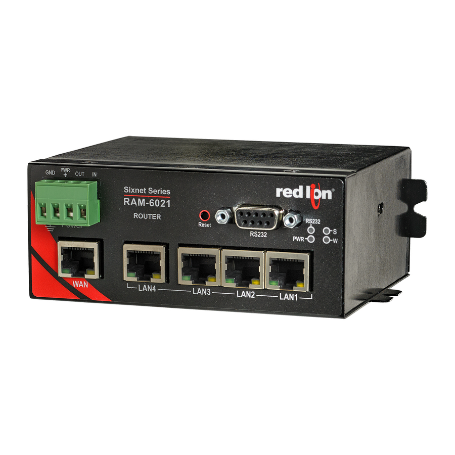
Page 8: Router View
1.1.3 Router View 1.1.4 Power Specifications and Consumption Power is supplied to the router via: • 4‐pin screw terminal • Side mounted DC 2.5 mm barrel connector router 4‐pin Screw Terminal Power is supplied to the router via the 4‐pin Screw Terminal on the front panel for the RAM‐6021 router. The pins are described as follows: Name Description Ground PWR+ Power supply input (8 to 30 VDC) Digital output Digital and analog input Power connector (facing front) DC 2.5mm Barrel Connector Power is supplied to the router via the barrel connector on the left side of the RAM‐6021 router. The contacts are described as follows: Name Description Sleeve Ground PWR+ Power supply input (8 to 30 VDC) Power connector (facing left side) Warning: DC 2.5mm barrel connector shall not be used in hazardous locations. Wired Router Hardware & Installation Guide Phone: 800.894.0412 - Fax: 888.723.4773 - Web: www.clrwtr.com - Email: info@clrwtr.com... - Page 9 Power specifications Power input to the router is protected against reverse polarity and over‐voltage. All routers are equipped with protection for reversed polarity and power surges over 33 volts. The routers are equipped with an internal 3 Amp fuse. Electrical Specifications and Pinout 1x Digital Output (DOUT) Configuration: Open Collector, reference to ground Absolute Maximum IDC: 500mADC (Vce = 750mVDC) Absolute Maximum VDC: 30VDC (open circuit) Absolute Minimum VDC: ‐0.4VDC (open circuit) 1x Digital Input (DIN) Configuration: un‐isolated level detection, reference to ground Active level: 1.6VDC to 30VDC Inactive level: 0VDC to 1.3VDC Absolute Minimum VDC: ‐0.3VDC Absolute Maximum VDC: 33VDC Leakage IDC at 5VDC: 150uADC 1x Analog Input (Shared with Digital Input) (DIN/AI1) Configuration: un‐isolated input, reference to ground Resolution: 1024 (ADC 10‐bit) VDC per step: 4.8875855mVDC Full scale level: 5VDC Zero level: 0VDC Absolute Minimum VDC: ‐0.3VDC Absolute Maximum VDC: 8.3VDC Leakage IDC at 5VDC: 265.96uADC TYPE Wired Router Hardware & Installation Guide Phone: 800.894.0412 - Fax: 888.723.4773 - Web: www.clrwtr.com - Email: info@clrwtr.com...
-
Page 10: Indicator Lights (Led)
Data Interface Specifications: Serial, Ethernet & USB 1.1.6.1 Ethernet Port The router's 10/100Mbps Ethernet port is compliant with the EIA‐568 standard. The router's ports are autosensing so they can be used with either a straight or crossover RJ45 cable to connect to host ports. The RAM‐6021 Router features a 5‐port Ethernet switch allowing connectivity to multiple local devices. 1.1.6.2 USB Device Port This is a USB 2.0 Device interface on a Mini B connector. It offers Ethernet‐over‐USB functionality using the RNDIS driver for Windows XP and Windows Vista Operating systems only. The BlueTree RNDIS driver must be installed before the USB interface can be used. The driver and instructions can be obtained at Red Lion website. Note: With firmware version 4.17 and later, standard Windows RNDIS drivers are used and no additional driver is required from Red Lion website. The unit is compatible with Windows 7/8 and other operating systems (OSX, Linux, etc). 1.1.6.3 Serial Port The router's serial port is an RS232 DCE, compliant with EIA‐232 standard. The connector used is DB9 female and is shown in the illustration below. Figure 1 – Serial connector (looking at front of router) For further serial wiring information, refer to the Hardware Installation section of this manual. Wired Router Hardware & Installation Guide Phone: 800.894.0412 - Fax: 888.723.4773 - Web: www.clrwtr.com - Email: info@clrwtr.com... -
Page 11: Reset Button Functions
1.1.7 RESET Button Functions Mode Pattern Description Hard Reset Press and hold for less than 3 seconds. Standard reboot Press and hold between 3 and 10 To restore default settings for older versions, seconds. Factory Restore rerun the SN Reflashing procedure found on our website. RS232 LED flashes quickly Puts the router in advanced firmware upgrade Press and hold between 10 and 15 mode by restarting the router and running the boot FW Upgrade seconds. W LED flashes quickly loader only. Do not use this mode unless instructed to by Red Lion Technical Support. Wired Router Hardware & Installation Guide Phone: 800.894.0412 - Fax: 888.723.4773 - Web: www.clrwtr.com - Email: info@clrwtr.com... -
Page 12: Chapter 2 Hardware Installation
Chapter 2 Hardware Installation Mounting the RAM-6021 Wired Router There are 3 different ways to mount a RAM‐6021 wired router: • Horizontally using two screws (#6 up to #10) pan or fillister head onto its horizontal mounting feet. • Vertically using two screws (#6 up to #10) pan or fillister head onto its vertical mounting feet. • Vertically using the supplied DIN rail clip. Note: Allow enough room to route the Ethernet, serial, I/O and other cables. DIN Rail Mounting & Removal The RAM‐6021 has a DIN rail clip pre‐mounted to the back of the unit. To panel mount the unit, the clip can be removed easily by removing the three (3) screws holding it in place. See the image at right for reference. The DIN clip has an integral spring mechanism that keeps it securely attached to the rail. Refer to the diagrams below for how to mount and remove the unit to a standard EN50022 DIN rail. Note: For best performance it is recommended that a DIN rail spacer (such as an end clamp) be used between the RTU and adjacent devices. This will leave an air gap for best heat dissipation off of the case. Mounting Instructions: Wired Router Hardware & Installation Guide Phone: 800.894.0412 - Fax: 888.723.4773 - Web: www.clrwtr.com - Email: info@clrwtr.com... -
Page 13: Ethernet Cable
Ethernet Cable If you are connecting to the router via the Ethernet port, you will need a straight or crossover category 5 cable with two 8‐pin RJ45 connectors on each end. To visually confirm that Ethernet cabling was done properly, check the LED indication on the Ethernet port located on the front panel of the router. The Link LED should be on when the right cable is used. USB Cable This is an Ethernet‐over‐USB connection which behaves like an Ethernet connection. If you are connecting to the router via the USB port, you will need a Type A plug to Type B plug USB cable for the mini Type B plug to Type A plug for the RAM‐ 6021 wired router In order for the USB connection to work, you need to install the Sixnet USB driver which is available at Red Lion website. Note: With firmware version 4.17 and later, standard Windows RNDIS drivers are used and no additional driver is required from Red Lion website. The unit is compatible with Windows 7/8 and other operating systems (OSX, Linux, etc). Serial Cable The router has all of its serial port pins enabled. If all the pins are enabled on the attached serial device, it is important to know whether the device is using DTE or DCE as a communication mode. Wired Router Hardware & Installation Guide Phone: 800.894.0412 - Fax: 888.723.4773 - Web: www.clrwtr.com - Email: info@clrwtr.com... -
Page 14: Power Source
The router is a DCE device, so use a straight‐through serial cable between the router and a DTE device such as a terminal. Use a NULL router cable adapter between the router and a DCE device such as another router. If using custom wiring or if some pins are disabled, follow the guidelines below. The wiring will vary depending on whether the attached serial device is a DTE or DCE. Power Source IMPORTANT Any installation involving electrical wiring and connections should be done by someone who is experienced in this field. As described in the Power specifications and consumption section, the router can be powered using: • 4‐pin screw terminal • Side mounted 2.5mm barrel connector WARNING DC 2.5mm barrel connector shall not be used in hazardous locations. Wired Router Hardware & Installation Guide Phone: 800.894.0412 - Fax: 888.723.4773 - Web: www.clrwtr.com - Email: info@clrwtr.com... -
Page 15: Chapter 3 Service And Support Information
Chapter 3 Service and Support Information Service Information We sincerely hope that you never experience a problem with any Red Lion product. If you do need service, call Red Lion at 1‐877‐432‐9908 for Technical Support. A trained specialist will help you quickly determine the source of the problem. Many problems are easily resolved with a single phone call. If it is necessary to return a unit to us, an RO (Repair Order) can be obtained on the Red Lion website. Red Lion tracks the flow of returned material with our RO system to ensure speedy service. You must include this RO num‐ ber on the outside of the box so that your return can be processed immediately. Be sure to have your original purchase order number and date purchased available. We suggest that you give us a repair purchase order number in case the repair is not covered under our warranty. You will not be billed if the repair is covered under warranty. Please supply us with as many details about the problem as you can. The information you supply will be written on the RO form and supplied to the repair department before your unit arrives. This helps us to provide you with the best service, in the fastest manner. Repairs are completed as soon as possible. If you need a quicker turnaround, ship the unit to us by air freight. We give priority service to equipment that arrives by overnight delivery. We apologize for any inconvenience that the need for repair may cause you. We hope that our rapid service meets your needs. If you have any suggestions to help us improve our service, please give us a call. We appreciate your ideas and will respond to them. For Your Convenience: Please fill in the following and keep this manual with your RED LION system for future reference: P.O. #:__________________ Date Purchased: ___________________ Purchased From:______________________________________________ Wired Router Hardware & Installation Guide Phone: 800.894.0412 - Fax: 888.723.4773 - Web: www.clrwtr.com - Email: info@clrwtr.com...
Need help?
Do you have a question about the RAM-6021 and is the answer not in the manual?
Questions and answers