red lion N-Tron Series Hardware Manual
Managed industrial ethernet switches
Hide thumbs
Also See for N-Tron Series:
- Software user manual (146 pages) ,
- Hardware manual (120 pages) ,
- User manual (40 pages)
Table of Contents
Advertisement
Quick Links
Download this manual
See also:
Software User Manual
Advertisement
Chapters
Table of Contents
Troubleshooting

Subscribe to Our Youtube Channel
Related Manuals for red lion N-Tron Series


Summary of Contents for red lion N-Tron Series
- Page 1 ® N-Tron Series 700/7000 Models - Volume I Managed Industrial Ethernet Switches Hardware Manual | August 2019 LP0988 | Revision B...
- Page 2 COPYRIGHT ©2019 Red Lion Controls, Inc. All rights reserved. Red Lion, the Red Lion logo, N‐Tron and N‐Ring are trademarks of Red Lion Controls, Inc. All other company and product names are trademarks of their respective owners. Red Lion Controls, Inc. 20 Willow Springs Circle York, PA 17406 CONTACT INFORMATION: Inside US: +1 (877) 432-9908 Outside US: +1 (717) 767-6511 Website: www.redlion.net Support: support.redlion.net...
-
Page 3: Table Of Contents
Revised 2019-08-22 Table of Contents Drawing No. LP0988 Table of Contents Preface ..............iv Disclaimer . - Page 4 Table of Contents Revised 2019-08-22 Drawing No. LP0988 1.4.3 708FX2 Dimensions ........... . 1-8 708M12 .
- Page 5 Revised 2019-08-22 Table of Contents Drawing No. LP0988 2.3.1 DIN-Rail Mounting Instructions for 708TX and 708FX2 Models ....2-38 Vertical Mounting 708TX and 708FX2 ........2-38 Horizontal Mounting 708TX and 708FX2 .
-
Page 6: Preface
While every effort has been made to ensure that this document is complete and accurate at the time of release, the information that it contains is subject to change. Red Lion Controls is not responsible for any additions to or alterations of the original document. -
Page 7: Environmental Impact Statement
As needed, Documentation Notes and or Product Bulletins will be provided between major releases to describe any new information or document changes. The latest online version of this document and all product updates can be accessed through the Red Lion web site http://www.redlion.net Publication History... -
Page 8: Related Documents
7012FX2 7026TX 7506GX2 7900 Visit the Technical Resources page on the Red Lion website at the following link to view available documents related to this product. www.redlion.net/n-tron_documentation Document Comments Red Lion appreciates all comments that will help us to improve our documentation quality. The user can submit comments through the Red Lion Customer Service. -
Page 9: Electrical Safety Warnings / Avertissements De Sécurité Électrique
Preface Revised 2019-08-22 Drawing No. LP0988 CAUTION: Do not operate the equipment in a manner not specified by this manual. ATTENTION: Ne pas faire fonctionner l'équipement d'une manière non spécifiée par ce manuel. WARNING: Install only in accordance with Local and National Codes of authorities having jurisdiction. -
Page 10: Environmental Safety Cautions And Warnings / Sécurité Environnementale Mises En Garde Et Avertissements
Revised 2019-08-22 Preface Drawing No. LP0988 WARNING: Properly ground the unit before connecting anything else to the unit. Units not properly grounded may result in a safety risk and could be hazardous and may void the warranty. See the grounding technique section of this manual for proper ways to ground the unit. AVERTISSEMENT: L'unité... -
Page 11: Dangereux
Preface Revised 2019-08-22 Drawing No. LP0988 WARNING: Disconnect the power and allow to cool 5 minutes before touching. AVERTISSEMENT: Déconnectez le câble d'alimentation et laisser refroidir 5 minutes avant de la toucher. Hazardous Location Warnings / Les Avertissements d'Emplacement Dangereux CAUTION: This equipment is suitable for use in Class I, Division 2, Groups A, B, C, and D or non-hazardous locations only. -
Page 12: Laser Safety Warnings / Avertissements De Sécurité Laser
Revised 2019-08-22 Preface Drawing No. LP0988 WARNING: Disconnect the power cable before removing any enclosure panel. AVERTISSEMENT: Débrancher le câble d'alimentation avant de retirer tout panneau de boîtier. WARNING: Use 60/75°C rated Copper wire for models 708TX, 708FX(E)2, and 90°C or higher for models 716TX, 716FX(E)2, 7018TX, 7018FX(E)2, and 110°C or higher for models 708M12, and 716M12. -
Page 13: Regulatory Certifications And Approvals
Preface Revised 2019-08-22 Drawing No. LP0988 Regulatory Certifications and Approvals 708M12 716TX 716FX2 716FX2 716M12 7018TX 7018FX2 Specification/Model 708TX 708FX2 708M12 716TX 716M12 7018TX 7018FX2 - HV - HV - HV - HV Product Safety UL 508, ANSI/ISA-12.12.01, Nonincendive Electrical Equipment for Use in Class I and II, Division 2 and Class III, Division 1 and 2 Hazardous (Classified) Locations, or Non-Hazardous... - Page 14 Revised 2019-08-22 Preface Drawing No. LP0988 708M12 716TX 716FX2 716FX2 716M12 7018TX 7018FX2 Specification/Model 708TX 708FX2 708M12 716TX 716M12 7018TX 7018FX2 - HV - HV - HV - HV Other ABS (PDA and Type Approval for Shipboard Applications) EMC Directive 2014/30/EU Low Voltage Directive 2014/35/EU DNV GL Type Approval Certification...
-
Page 15: Chapter 1 Product Overview
Drawing No. LP0988 Chapter 1 Product Overview 1.1 Common Features ® Red Lion's N-Tron series 700/7000 managed Industrial Gigabit Ethernet switches offer a wide array of port configurations and media types. See “Available Models” for a list of the 700/7000 models covered in this ®... -
Page 16: Available Models
Revised 2019-08-22 Product Overview Drawing No. LP0988 Available Models 1.2 Available Models 10/100 TX Total Operating 100 FX Redundant HV Option Model Mounting RJ45 Copper SFPs*** Ports Temperature Ports Power Input Power Input Ports 708TX DIN-Rail -40 °C to 85 °C 10-30 VDC 708FX2 DIN-Rail... -
Page 17: Features And Benefits
Product Overview Revised 2019-08-22 708TX Drawing No. LP0988 1.3 708TX The versatile 708TX Industrial Ethernet managed switch features eight 10/100 BaseTX RJ45 copper ports housed in a hardened metal DIN-Rail enclosure with redundant 10-30 VDC power inputs. Designed to handle the most demanding environments, the 708TX offers expanded shock and vibration ratings and wide -40 °C to 85 °C operating temperature rating.The 708TX combines outstanding performance and ease of use. -
Page 18: 708Tx Specifications
Revised 2019-08-22 Product Overview Drawing No. LP0988 708TX 1.3.2 708TX Specifications Mechanical Height Width Depth Weight Mount 2.27" (5.8 cm) 6.0" (15.3 cm) 3.75" (9.6 cm) 1.7 lbs (0.8 kg) 35mm DIN-Rail Power Input Input Voltage Steady Input Current Inrush Current BTU/hr 10-30 VDC 250 mA @ 24 VDC 11.8 A /0.1 ms @ 24... -
Page 19: 708Tx Dimensions
Product Overview Revised 2019-08-22 708TX Drawing No. LP0988 1.3.3 708TX Dimensions All specifications are subject to change. Consult the company website for more information. ® N-Tron Series 700/7000 Managed Industrial Ethernet Switch Hardware Manual - Volume I... -
Page 20: Features And Benefits
Revised 2019-08-22 Product Overview Drawing No. LP0988 708FX2 1.4 708FX2 The versatile 708FX2 Industrial Ethernet managed switch features six 10/100 BaseTX RJ45 copper ports and two 100Base ST or SC fiber ports housed in a hardened metal DIN-Rail enclosure with redundant 10-30 VDC power inputs. -
Page 21: 708Fx2 Specifications
Product Overview Revised 2019-08-22 708FX2 Drawing No. LP0988 1.4.2 708FX2 Specifications Mechanical Height Width Depth Weight Mount 2.27" (5.8 cm) 6.0" (15.3 cm) 4.70" (11.94 cm) 1.7 lbs (0.8 kg) 35mm DIN-Rail Power Input Input Voltage Steady Input Current Inrush Current BTU/hr 10-30 VDC 330 mA @ 24 VDC 11.8 A /0.1 ms @ 24... -
Page 22: 708Fx2 Dimensions
Revised 2019-08-22 Product Overview Drawing No. LP0988 708FX2 1.4.3 708FX2 Dimensions All specifications are subject to change. Consult the company website for more information. ® N-Tron Series 700/7000 Managed Industrial Ethernet Switch Hardware Manual - Volume I... -
Page 23: Features And Benefits
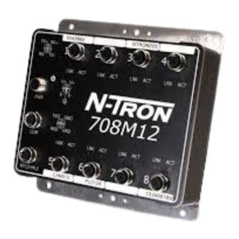
Product Overview Revised 2019-08-22 708M12 Drawing No. LP0988 1.5 708M12 The versatile 708M12 Industrial Ethernet managed switch features eight 10/100 BaseTX M12 D-coded copper ports and redundant 10-30 VDC power inputs (HV 40-160 VDC available). Designed to handle the most demanding environments with IP rated protection against exposure to low/high pressure water jets and protection against temporary immersion in water. -
Page 24: 708M12 Specifications
Revised 2019-08-22 Product Overview Drawing No. LP0988 708M12 1.5.2 708M12 Specifications Mechanical Height Width Depth Weight Mount 6.7" (16.9 cm) 6.7" (16.9 cm) 1.8" (4.6 cm) 3.4 lbs (1.6 kg) 35mm DIN-Rail (Optional) Power Input Input Voltage Steady Input Current Inrush Current BTU/hr 10-30 VDC 250 mA @ 24 VDC... -
Page 25: 708M12 Dimensions
Product Overview Revised 2019-08-22 708M12 Drawing No. LP0988 1.5.3 708M12 Dimensions All specifications are subject to change. Consult the company website for more information. ® N-Tron Series 700/7000 Managed Industrial Ethernet Switch Hardware Manual - Volume I 1-11... -
Page 26: Features And Benefits
Revised 2019-08-22 Product Overview Drawing No. LP0988 716TX 1.6 716TX The versatile 716TX Industrial Ethernet managed switch features 16 10/100 BaseTX RJ45 copper ports housed in a hardened metal DIN-Rail enclosure with redundant 10-30 VDC power inputs (HV 40-160 VDC available). Designed to handle the most demanding environments, the 716TX offers expanded shock and vibration ratings and wide -40 °C to 70 °C operating temperature rating.The 716TX combines outstanding performance and ease of use. -
Page 27: 716Tx Specifications
Product Overview Revised 2019-08-22 716TX Drawing No. LP0988 1.6.2 716TX Specifications Mechanical Height Width Depth Weight Mount 2.27" (5.8 cm) 8.25" (20.95 cm) 4.75" (12.06 cm) 3.3 lbs (1.49 kg) 35mm DIN-Rail Power Input Input Voltage Steady Input Current BTU/hr 10-30 VDC 620 mA @ 24 VDC 50.8 @ 24 VDC (Regulated) -
Page 28: 716Tx Dimensions
Revised 2019-08-22 Product Overview Drawing No. LP0988 716TX 1.6.3 716TX Dimensions All specifications are subject to change. Consult the company website for more information. ® 1-14 N-Tron Series 700/7000 Managed Industrial Ethernet Switch Hardware Manual - Volume I... -
Page 29: Features And Benefits
Product Overview Revised 2019-08-22 716FX2 Drawing No. LP0988 1.7 716FX2 The versatile 716FX2 Industrial Ethernet managed switch features 14 10/100 BaseTX RJ45 copper ports and two 100Base ST or SC fiber ports housed in a hardened metal DIN-Rail enclosure with redundant 10-30 VDC power inputs (HV 40-160 VDC available). -
Page 30: 716Fx2 Specifications
Revised 2019-08-22 Product Overview Drawing No. LP0988 716FX2 1.7.2 716FX2 Specifications Mechanical Height Width Depth Weight Mount 2.27" (5.8 cm) 8.25" (20.95 cm) 5.85" (14.86 cm) 3.3 lbs (1.49 kg) 35mm DIN-Rail Power Input Input Voltage Steady Input Current BTU/hr 10-30 VDC 620 mA @ 24 VDC 50.8 @ 24 VDC (Regulated) -
Page 31: 716Fx2 Dimensions
Product Overview Revised 2019-08-22 716FX2 Drawing No. LP0988 1.7.3 716FX2 Dimensions All specifications are subject to change. Consult the company website for more information. ® N-Tron Series 700/7000 Managed Industrial Ethernet Switch Hardware Manual - Volume I 1-17... -
Page 32: Features And Benefits
Revised 2019-08-22 Product Overview Drawing No. LP0988 716M12 1.8 716M12 The versatile 716M12 Industrial Ethernet managed switch features 16 10/100 BaseTX M12 D-Coded copper ports and redundant 10-49 VDC power inputs (HV 40-160 VDC available). Designed to handle the most demanding environments with IP rated protection against exposure to low/high pressure water jets and protection against temporary immersion in water. -
Page 33: 716M12 Specifications
Product Overview Revised 2019-08-22 716M12 Drawing No. LP0988 1.8.2 716M12 Specifications Mechanical Height Width Depth Weight Mount 6.7" (16.9 cm) 6.7" (16.9 cm) 2.2" (5.6 cm) 4.6 lbs (2.1 kg) 35mm DIN-Rail (Optional) Power Input Input Voltage Steady Input Current Inrush Current BTU/hr 10-49 VDC 350 mA @ 24 VDC... -
Page 34: 716M12 Dimensions
Revised 2019-08-22 Product Overview Drawing No. LP0988 716M12 1.8.3 716M12 Dimensions All specifications are subject to change. Consult the company website for more information. ® 1-20 N-Tron Series 700/7000 Managed Industrial Ethernet Switch Hardware Manual - Volume I... -
Page 35: Features And Benefits
Product Overview Revised 2019-08-22 7018TX Drawing No. LP0988 1.9 7018TX The versatile 7018TX Industrial Ethernet managed switch features 16 10/100 BaseTX RJ45 copper ports and two optional SFP (Mini-GBIC) transceiver ports housed in a hardened metal DIN-Rail enclosure with redundant 10-30 VDC power inputs (HV 40-160 VDC available). -
Page 36: 7018Tx Specifications
Revised 2019-08-22 Product Overview Drawing No. LP0988 7018TX 1.9.2 7018TX Specifications Mechanical Height Width Depth Weight Mount 2.27" (5.8 cm) 8.25" (20.95 cm) 4.75" (12.06 cm) 3.3 lbs (1.49 kg) 35mm DIN-Rail Power Input Input Voltage Steady Input Current BTU/hr 10-30 VDC 620 mA @ 24 VDC 50.8 @ 24 VDC (Regulated) -
Page 37: 7018Tx Dimensions
Product Overview Revised 2019-08-22 7018TX Drawing No. LP0988 1.9.3 7018TX Dimensions All specifications are subject to change. Consult the company website for more information. ® N-Tron Series 700/7000 Managed Industrial Ethernet Switch Hardware Manual - Volume I 1-23... -
Page 38: 7018Fx2
Revised 2019-08-22 Product Overview Drawing No. LP0988 7018FX2 1.10 7018FX2 The versatile 7018FX2 Industrial Ethernet managed switch features 14 10/100 BaseTX RJ45 copper ports, up to two optional SFP transceiver ports and two 100Base ST or SC fiber ports housed in a hardened metal DIN-Rail enclosure with redundant 10-30 VDC power inputs (HV 40-160 VDC available). -
Page 39: 7018Fx2 Specifications
Product Overview Revised 2019-08-22 7018FX2 Drawing No. LP0988 1.10.2 7018FX2 Specifications Mechanical Height Width Depth Weight Mount 2.27" (5.8 cm) 8.25" (20.95 cm) 4.75" (12.06 cm) 3.3 lbs (1.49 kg) 35mm DIN-Rail Power Input Input Voltage Steady Input Current BTU/hr 10-30 VDC 620 mA @ 24 VDC 50.8 @ 24 VDC (Regulated) -
Page 40: 7018Fx2 Dimensions
Revised 2019-08-22 Product Overview Drawing No. LP0988 7018FX2 1.10.3 7018FX2 Dimensions All specifications are subject to change. Consult the company website for more information. ® 1-26 N-Tron Series 700/7000 Managed Industrial Ethernet Switch Hardware Manual - Volume I... -
Page 41: Transceiver Characteristics
Product Overview Revised 2019-08-22 Transceiver Characteristics Drawing No. LP0988 1.11 Transceiver Characteristics 1.11.1 100 MB Fiber Transceiver Characteristics Fiber Length 2 km* 15 km** 40 km** 80 km** TX Power Min -19 dBm -15 dBm -5 dBm -5 dBm RX Sensitivity Max -31 dBm -31 dBm -34 dBm -34 dBm Wavelength... -
Page 42: Leds
Revised 2019-08-22 Product Overview Drawing No. LP0988 LEDs 1.12 LEDs Data ports have two LEDs located on each connector. The left LED indicates link status, and the right LED indicates activity. labeled LNK and ACT. The LNK LED indicates link status and the ACT LED indicates activity. RJ45 ports FX ports M12 ports... -
Page 43: Ordering Guide
Product Overview Revised 2019-08-22 Ordering Guide Drawing No. LP0988 1.13 Ordering Guide 1.13.1 708TX Part Number Description 708TX Eight Port 10/100Base-TX Ports Managed Industrial Ethernet Switch 700-PM Panel Mount Kit NTPS-24-1.3 Power Supply 1.3 Amp @ 24 VDC URMK 19” Universal Rack Mount Kit 1.13.2 708FX2 / 708FXE2 Part Number Description... -
Page 44: 716Tx
Revised 2019-08-22 Product Overview Drawing No. LP0988 Ordering Guide 1.13.3 716TX Part Number Description 716TX-VV 16 Port 10/100Base-TX Ports, Managed Industrial Ethernet Switch 700-PM Panel Mount Kit NTPS-24-1.3 Power Supply 1.3 Amp @ 24 VDC Power Supply 2 Amp @ 48 VDC (For use with -HV model only) NTPS-48-2 URMK 19”... -
Page 45: 716Fx2
Product Overview Revised 2019-08-22 Ordering Guide Drawing No. LP0988 1.13.4 716FX2 Part Number Description 716FX2-XX-VV 14 Port 10/100Base-TX Ports, Two Multimode 100BaseFX Fiber Optic Ports Managed Industrial Ethernet Switch 716FXE2-XX-YY-VV 14 Port 10/100Base-TX Ports, Two Singlemode 100BaseFX Fiber Optic Ports Managed Industrial Ethernet Switch 700-PM Panel Mount Kit NTPS-24-1.3... -
Page 46: 7018Tx
Revised 2019-08-22 Product Overview Drawing No. LP0988 Ordering Guide 1.13.5 7018TX Part Number Description 7018TX-VV 16 10/100Base-TX Ports, Two Optional Gigabit SFP Ports Managed Industrial Ethernet Switch NTSFP-TX 1000BaseT copper SFP (Mini-GBIC) Transceiver (RJ45 connector) NTSFP-SX 1000BaseSX multimode fiber SFP (Mini-GBIC) Transceiver (LC style connector) NTSFP-LX-ZZ 1000BaseLX singlemode fiber SFP (Mini-GBIC) Transceiver (LC style connector) 700-PM... -
Page 47: 7018Fx2
Product Overview Revised 2019-08-22 Ordering Guide Drawing No. LP0988 1.13.6 7018FX2 Part Number Description 7018FX2-XX-VV 14 10/100Base-TX Ports, Two Multimode 100BaseFX Fiber Optic Ports, Two Optional Gigabit SFP Ports Managed Industrial Ethernet Switch 7018FXE2-XX-YY-VV 14 10/100Base-TX Ports, Two Singlemode 100BaseFX Fiber Optic Ports, Two Optional Gigabit SFP Ports Managed Industrial Ethernet Switch NTSFP-TX 1000BaseT copper SFP (Mini-GBIC) Transceiver (RJ45 connector) -
Page 48: 708M12
Revised 2019-08-22 Product Overview Drawing No. LP0988 Ordering Guide 1.13.7 708M12 Part Number Description 708M12-VV IP67-rated, Eight 10/100Base-TX Ports, Managed Industrial Ethernet Switch with M12 D-coded female 4-pin connectors 700-NTCD-M12 Configuration Device for saving and restoring configuration parameters. NTPS-24-1.3 Power Supply 1.3 Amp @ 24 VDC NTPS-48-2 Power Supply 2 Amp @ 48 VDC (For use with -HV model only) M12DRC-ISO... -
Page 49: 716M12
Product Overview Revised 2019-08-22 Ordering Guide Drawing No. LP0988 1.13.8 716M12 Part Number Description 716M12-VV IP67-Rated, 16 10/100Base-TX Ports, Managed Industrial Ethernet Switch with M12 D-coded Female 4-pin Connectors 700-NTCD-M12 Configuration Device for saving and restoring configuration parameters. NTPS-24-1.3 Power Supply 1.3 Amp @ 24 VDC NTPS-48-2 Power Supply 2 Amp @ 48 VDC M12DRC-ISO... - Page 50 Revised 2019-08-22 Product Overview Drawing No. LP0988 Ordering Guide This Page Intentionally Left Blank ® 1-36 N-Tron Series 700/7000 Managed Industrial Ethernet Switch Hardware Manual - Volume I...
-
Page 51: Chapter 2 Hardware Installation
2.3 Mounting the Unit Red Lion offers its 700/7000 switch model Panel Mount Kit (P/N: 700-PM) which may be used to securely mount the 700/7000 models to a panel or other flat surface. Refer to section 1.16 to determine if your switch model works with the Panel Mount Kit. -
Page 52: Din-Rail Mounting Instructions For 708Tx And 708Fx2 Models
Revised 2019-08-22 Hardware Installation Drawing No. LP0988 Mounting the Unit 2.3.1 DIN‐Rail Mounting Instructions for 708TX and 708FX2 Models Install the unit on a standard 35mm Din-Rail. Recess the 708TX unit to allow at least 3” of horizontal clearance for copper cable bend radius. Recess the 708FX2 unit to allow at least 5” of horizontal clearance for fiber cable bend radius. -
Page 53: Din-Rail Mounting Instructions For 716Tx, 716Fx2, 7018Tx, And 7018Fx2 Models
Hardware Installation Revised 2019-08-22 Mounting the Unit Drawing No. LP0988 2.3.2 DIN‐Rail Mounting Instructions for 716TX, 716FX2, 7018TX and 7018FX2 Models Install the unit on a standard 35mm Din-Rail. Recess the 716TX unit to allow at least 3” of horizontal clearance for copper cable bend radius. Recess the 716FX2 or 7018FX2 unit to allow at least 5” of horizontal clearance for fiber cable bend radius. -
Page 54: Din-Rail Removal Instructions From Vertical Mounting
Revised 2019-08-22 Hardware Installation Drawing No. LP0988 Mounting the Unit 2.3.3 DIN‐Rail Removal Instructions From Vertical Mounting Remove the switch from standard 35mm DIN-Rail as shown in the diagram above. 1. Ensure power from the power source is off. 2. Disconnect power and ground wires. 3. Disconnect any communications cables from the unit. 4. -
Page 55: Horizontal Din-Rail Mounting 708M12 And 716M12
Hardware Installation Revised 2019-08-22 Mounting the Unit Drawing No. LP0988 708M12 and 716M12 Dimensions and Drill Hole Locations 708M12 716M12 2.3.5 Horizontal DIN‐Rail Mounting 708M12 and 716M12 Install the switch to standard 35mm DIN-Rail. 1. Attach the optional M12DRC or M12DRC-ISO DIN-Rail kit to the back of the switch. 2. Place the bottom edge of the bracket on the back of the unit against the DIN-Rail bottom edge at a downward angle. -
Page 56: Connect Power Source
Recommended 24 VDC power supply, similar to Red Lion’s P/N NTPS-24-1.3. For HV models, recommended 48 VDC power supply, similar to Red Lion’s P/N NTPS-48-2. Verify that the proper input voltage is connected to the switch before powering on the unit. -
Page 57: 708M12 And 716M12 Models
2.5 Grounding the Switch The grounding of any control system is an integral part of the design. Red Lion switches are designed to be grounded, but the user has been given the flexibility to float the switch when required. The best noise immunity and emissions (i.e. -
Page 58: Grounding 708Tx, 708Fx2, 716Tx, 716Fx2, 7018Tx, And 7018Fx2 Models
(i.e. thermocouples, RTD, etc.). CAT5e cables manufactured to EIA-568A or 568B specifications are required for use with Red Lion Switches. In the event all CAT5e patch cable distances are small (i.e. All Ethernet devices are located in the same local cabinet and/or referenced to the same earth ground), it is permissible to use fully shielded cables terminated to chassis ground at both ends in systems void of low level analog signals. -
Page 59: Connecting The Switch
(i.e. thermocouples, RTD, etc.). CAT5e cables manufactured to EIA-568A or 568B specifications are required for use with Red Lion Switches. In the event all CAT5e patch cable distances are small (i.e. All Ethernet devices are located in the same local cabinet and/or referenced to the same earth ground), it is permissible to use fully shielded cables terminated to chassis ground at both ends in systems void of low level analog signals. -
Page 60: Rj45 Connector Crimp Specifications
(i.e. thermocouples, RTD, etc.). CAT5e cables manufactured to EIA- 568A or 568B specifications are required for use with Red Lion series switches. In the event all CAT5e patch cables are short (i.e. All Ethernet devices are located in the same local cabinet and/or referenced to the same earth ground), it is permissible to use fully shielded cables terminated to chassis ground at both ends in systems avoid low level analog signals. -
Page 61: 708Tx, 708Fx2, 716Tx, 716Fx2, 7018Tx, And 7018Fx2 Model Serial Interface
Hardware Installation Revised 2019-08-22 Connecting the Switch Drawing No. LP0988 2.6.2 708TX, 708FX2, 716TX, 716FX2, 7018TX and 7018FX2 Model Serial Interface The 700/7000 switch models provide an EIA-232 interface accessed via a DB9-pin female connector (labeled ‘COM’ on the unit). This is used to access the Command Line Interface (CLI). The pin-outs are shown below. 2.6.2.1 Serial Cable Connection Connect the serial COM port of your PC and the 700/7000 model switch using a standard straight through serial... -
Page 62: 708M12 And 716M12 Model Serial Interface
100 meters. Red Lion recommends the use of pre-manufactured CAT5 cables with an M12 connector on the switch end to ensure the best performance. If this is not an option and users must terminate their own ends on the CAT5E cables;... -
Page 63: Configure The Terminal Interface
Clean only with a damp cloth. Excess moisture or harsh chemicals can cause damage to the unit. 2.9 Troubleshooting Troubleshooting the device is comprised of a few basic steps as provided below. If these do not resolve the issue then contact Red Lion as per the guidance provided in “Service Information” on page 1. Make sure the (Power LED) is ON. - Page 64 Revised 2019-08-22 Hardware Installation Drawing No. LP0988 Troubleshooting 2. Make sure you are supplying sufficient current for the version chosen. Note: The Inrush current will exceed the steady state current by ~ 2X. 3. Verify that Link LEDs are ON for connected ports. 4.
-
Page 65: Chapter 3 Accessing The Web Software Interface
Accessing the Web Software Interface Revised 2019-08-22 Drawing No. LP0988 Chapter 3 Accessing the Web Software Interface 1. Launch a web browser and enter the IP address of the device into the address bar. The DHCP Client is enabled by default with the 192.168.1.201 as the fallback address. 2. - Page 66 Revised 2019-08-22 Accessing the Web Software Interface Drawing No. LP0988 Please consult the 700/7000 Software Manual (LP0985) for configuration options. ® 3-52 N-Tron Series 700/7000 Managed Industrial Ethernet Switch Hardware Manual - Volume I...
- Page 67 Red Lion website. Red Lion tracks the flow of returned material with our RO system to ensure speedy service. You must include this RO number on the outside of the box so that your return can be processed immediately. Be sure to have your original purchase order number and date purchased available.
- Page 68 Drawing No. LP0988 Limited Warranty (a) Red Lion Controls Inc., (the “Company”) warrants that all Products shall be free from defects in material and workmanship under normal use for the period of time provided in “Statement of Warranty Periods” (available at www.redlion.net) current at the time of shipment of the Products (the “Warranty Period”).
- Page 69 Revised 2019-08-22 Limited Warranty Drawing No. LP0988 ® 3-55 N-Tron Series 700/7000 Managed Industrial Ethernet Switch Hardware Manual - Volume I...
- Page 70 ® N-Tron Series 700/7000 Models - Volume II Managed Industrial Ethernet Switches Hardware Manual | August 2019 LP0988 | Revision B...
- Page 71 COPYRIGHT ©2019 Red Lion Controls, Inc. All rights reserved. Red Lion, the Red Lion logo, N‐Tron and N‐Ring are registered trademarks of Red Lion Controls, Inc. All other company and product names are trademarks of their respective owners. Red Lion Controls, Inc. 20 Willow Springs Circle York, PA 17406 CONTACT INFORMATION: Inside US: +1 (877) 432-9908 Outside US: +1 (717) 767-6511 Website: www.redlion.net Support: support.redlion.net...
- Page 72 Table of Contents Revised 2019-08-22 Drawing No. LP0988 Table of Contents Preface . . . . . . . . . . . . . . . . . . . . . . . . . . . . . . . . . . . . . . . . . . . . . . . . . . . . . . . . . . . . . . . . . . . . . . . . . . . . . . . . . . . . . iv Disclaimer . . . . . . . . . . . . . . . . . . . . . . . . . . . . . . . . . . . . . . . . . . . . . . . . . . . . . . . . . . . . . . . . . . . . . . . . . . . . . . . . . . . iv Compliance Information . . . . . . . . . . . . . . . . . . . . . . . . . . . . . . . . . . . . . . . . . . . . . . . . . . . . . . . . . . . . . . . . . . . . . . . iv Part 15 of the Federal Communications Commission (FCC) - A Rules: Interference . . . . . . . . . . . . . . . . . iv Déclaration de conformité FCC . . . . . . . . . . . . . . . . . . . . . . . . . . . . . . . . . . . . . . . . . . . . . . . . . . . . . . . . . . . . . iv Industry Canada . . . . . . . . . . . . . . . . . . . . . . . . . . . . . . . . . . . . . . . . . . . . . . . . . . . . . . . . . . . . . . . . . . . . . . . . . .
- Page 73 Revised 2019-08-22 Table of Contents Drawing No. LP0988 1.6.1 Features and Benefits . . . . . . . . . . . . . . . . . . . . . . . . . . . . . . . . . . . . . . . . . . . . . . . . . . . . . . . . . . . . . 1‐15 1.6.2 712FX4 Specifications . . . . . . . . . . . . . . . . . . . . . . . . . . . . . . . . . . . . . . . . . . . . . . . . . . . . . . . . . . . . . 1‐16 1.6.3 712FX4 Dimensions . . . . . . . . . . . . . . . . . . . . . . . . . . . . . . . . . . . . . . . . . . . . . . . . . . . . . . . . . . . . . . . 1‐17 1.6.4 712FX4‐HV Dimensions . . . . . . . . . . . . . . . . . . . . . . . . . . . . . . . . . . . . . . . . . . . . . . . . . . . . . . . . . . . . 1‐18 1.7 714FX6 . . . . . . . . . . . . . . . . . . . . . . . . . . . . . . . . . . . . . . . . . . . . . . . . . . . . . . . . . . . . . . . . . . . . . . . . . . . . . . . . 1‐19 1.7.1 Features and Benefits . . . . . . . . . . . . . . . . . . . . . . . . . . . . . . . . . . . . . . . . . . . . . . . . . . . . . . . . . . . . . 1‐19 1.7.2 714FX6 Specifications . . . . . . . . . . . . . . . . . . . . . . . . . . . . . . . . . . . . . . . . . . . . . . . . . . . . . . . . . . . . . 1‐20 1.7.3 714FX6 Dimensions . . . . . . . . . . . . . . . . . . . . . . . . . . . . . . . . . . . . . . . . . . . . . . . . . . . . . . . . . . . . . . . 1‐21 1.8 7010TX . . . . . . . . . . . . . . . . . . . . . . . . . . . . . . . . . . . . . . . . . . . . . . . . . . . . . . . . . . . . . . . . . . . . . . . . . . . . . . . . 1‐22 1.8.1 Features and Benefits . . . . . . . . . . . . . . . . . . . . . . . . . . . . . . . . . . . . . . . . . . . . . . . . . . . . . . . . . . . . .
- Page 74 Table of Contents Revised 2019-08-22 Drawing No. LP0988 Chapter 2 Hardware Installation . . . . . . . . . . . . . . . . . . . . . . . . . . . . . . . . . . . . . . . . . . . . . . . . . . . . . . . . . 2‐53 2.1 Unpacking . . . . . . . . . . . . . . . . . . . . . . . . . . . . . . . . . . . . . . . . . . . . . . . . . . . . . . . . . . . . . . . . . . . . . . . . . . . . . 2‐53 2.2 Mounting the Switch. . . . . . . . . . . . . . . . . . . . . . . . . . . . . . . . . . . . . . . . . . . . . . . . . . . . . . . . . . . . . . . . . . . . . 2‐53 2.3.1 DIN-Rail Mounting Instructions 709FX, 710FX2, 711FX3, 712FX4, 714FX6, 7010TX, 7012FX2, 7506GX2, and 7900 Models . . . . . . . . . . . . . . . . . . . . . . . . . . . . . . . . . . . . . . . . . . . . . . . . . . . . . . . . 2‐53 2.3.2 DIN-Rail Removal Instructions 709FX, 710FX2, 711FX3, 712FX4, 714FX6, 7010TX, 7012FX2, and 7506GX2 Models . . . . . . . . . . . . . . . . . . . . . . . . . . . . . . . . . . . . . . . . . . . . . . . . . . . . . . . . . . . . . .
-
Page 75: Preface
While every effort has been made to ensure that this document is complete and accurate at the time of release, the information that it contains is subject to change. Red Lion Controls is not responsible for any additions to or... -
Page 76: Environmental Impact Statement
As needed, Documentation Notes and or Product Bulletins will be provided between major releases to describe any new information or document changes. The latest online version of this document and all product updates can be accessed through the Red Lion web site http://www.redlion.net Publication History... -
Page 77: Related Documents
708M12 716M12 7018TX 7018FX2 Visit the Technical Resources page on the Red Lion website at the following link to view available documents related to this product. www.redlion.net Document Comments Red Lion appreciates all comments that will help us to improve our documentation quality. The user can submit comments through the Red Lion Customer Service. -
Page 78: Kc Mark (Korea)
Revised 2019-08-22 Preface Drawing No. LP0988 CAUTION: Do not operate the equipment in a manner not specified by this manual. ATTENTION: Ne pas faire fonctionner l'équipement d'une manière non spécifiée par ce manuel. WARNING: Install only in accordance with Local and National Codes of authorities having jurisdiction. -
Page 79: Environmental Safety Cautions And Warnings / Sécurité Environnementale Mises En Garde Et Avertissements
Preface Revised 2019-08-22 Drawing No. LP0988 WARNING: Power must be supplied by an isolating source and a UL-rated in-line 2.5A fuse must be installed immediately before the unit. AVERTISSEMENT: Celui-ci doit être alimenté par une source d'isolement et une homologués UL en-ligne fusible 2,5A doit être installé... -
Page 80: Hazardous Location Warnings / Les Avertissements D'emplacement Dangereux
Revised 2019-08-22 Preface Drawing No. LP0988 Hazardous Location Warnings / Les Avertissements d'Emplacement Dangereux CAUTION: This equipment is suitable for use in Class I, Division 2, Groups A, B, C, and D or non-hazardous locations only. Combinations of equipment in your system are subject to investigation by the local authority having jurisdiction at the time of installation. ATTENTION: Cet appareil est adapté... -
Page 81: Laser Safety Warnings / Avertissements De Sécurité Laser
Preface Revised 2019-08-22 Drawing No. LP0988 WARNING: Disconnect the power cable before removing any enclosure panel. AVERTISSEMENT: Débrancher le câble d'alimentation avant de retirer tout panneau de boîtier. Note: Use 90 °C or higher rated copper wire, 0.22 Nm 2lb/in tightening torque for field installed conductors for 709FX, 710FX2, 711FX3, 712FX4, 714FX6, 7010TX, 7012FX2, 7506GX2 and 7900 models. -
Page 82: Regulatory Certifications And Approvals
Revised 2019-08-22 Preface Drawing No. LP0988 Regulatory Certifications and Approvals 709FX 709FX- 710FX2 710FX2 - 711FX3 711FX3 712FX4 712FX4 7012FX2 Specification/Model 714FX6 7010TX 7012FX2 7026TX 7506GX2 7900 Product Safety UL 508, ANSI/ISA-12.12.01, Nonincendive Electrical Equipment for Use in Class I and II, Division 2 and Class III, Division 1 and 2 Hazardous (Classified) Locations, or Non-... - Page 83 Preface Revised 2019-08-22 Drawing No. LP0988 709FX 709FX- 710FX2 710FX2 - 711FX3 711FX3 712FX4 712FX4 7012FX2 Specification/Model 714FX6 7010TX 7012FX2 7026TX 7506GX2 7900 Designed to comply with NEMA TS1/TS2 Traffic Control ABS (PDA and Type Approval for Shipboard Applications) Other RoHS 2 Directive 2011/65/ RoHS 3 Directive (EU) 2015/863*...
-
Page 84: Chapter 1 Product Overview
Product Overview 1.1 Common Features ® Red Lion's N-Tron series 700/7000 managed Industrial Gigabit Ethernet switches offer a wide array of port configurations and media types. See “Available Models” on page 2. for a list of the 700/7000 models covered in this document. -
Page 85: Available Models
Revised 2019-08-22 Product Overview Drawing No. LP0988 Available Models 1.2 Available Models 10/100 TX Total Operating 100 FX Redundant HV Option Part # Mounting RJ45 Copper SFPs** Ports Temperature Ports Power Input Power Input Ports 709FX DIN-Rail -40 °C to 70 °C 10-49 VDC 43-300 VDC* 710FX2... -
Page 86: 709Fx
Product Overview Revised 2019-08-22 709FX Drawing No. LP0988 1.3 709FX The versatile 709FX Industrial Ethernet switch is a fully managed switch that features eight 10/100 BaseTX RJ45 copper ports and one 100Base ST or SC fiber port housed in a hardened metal DIN-Rail enclosure with redundant 10-49 VDC power inputs (HV 43-300 VDC available). -
Page 87: 709Fx Specifications
Revised 2019-08-22 Product Overview Drawing No. LP0988 709FX 1.3.2 709FX Specifications Mechanical Height Width Depth Weight Mount 4.3" (10.8 cm) 2.4" (6.1 cm) 4.6" (11.7 cm) 1.4 lbs (0.64 kg) 35mm DIN-Rail 3.1" (7.9 cm) * 1.6 lbs (0.73 kg) * Power Input Input Voltage Steady Input Current BTU/hr... -
Page 88: 709Fx Dimensions
Product Overview Revised 2019-08-22 709FX Drawing No. LP0988 1.3.3 709FX Dimensions All specifications are subject to change. Consult the company website for more information. ® N-Tron Series 700/7000 Managed Industrial Ethernet Switch Hardware Manual - Volume II... -
Page 89: 709Fx-Hv Dimensions
Revised 2019-08-22 Product Overview Drawing No. LP0988 709FX 1.3.4 709FX‐HV Dimensions All specifications are subject to change. Consult the company website for more information. ® N-Tron Series 700/7000 Managed Industrial Ethernet Switch Hardware Manual - Volume II... -
Page 90: 710Fx2
Product Overview Revised 2019-08-22 710FX2 Drawing No. LP0988 1.4 710FX2 The versatile 710FX2 Industrial Ethernet switch is a fully managed switch that features eight 10/100 BaseTX RJ45 copper ports and two 100Base ST or SC fiber ports housed in a hardened metal DIN-Rail enclosure with redundant 10-49 VDC power inputs (HV 43-300 VDC available). -
Page 91: 710Fx2 Specifications
Revised 2019-08-22 Product Overview Drawing No. LP0988 710FX2 1.4.2 710FX2 Specifications Mechanical Height Width Depth Weight Mount 4.3" (10.9 cm) 2.4" (6.1 cm) 4.6" (11.7 cm) 1.4 lbs (0.64 kg) 35mm DIN-Rail 3.1" (7.9 cm)* 1.6 lbs (0.73 kg)* Power Input Input Voltage Steady Input Current BTU/hr 415 mA @ 24 VDC... -
Page 92: 710Fx2 Dimensions
Product Overview Revised 2019-08-22 710FX2 Drawing No. LP0988 1.4.3 710FX2 Dimensions All specifications are subject to change. Consult the company website for more information. ® N-Tron Series 700/7000 Managed Industrial Ethernet Switch Hardware Manual - Volume II... -
Page 93: 710Fx2-Hv Dimensions
Revised 2019-08-22 Product Overview Drawing No. LP0988 710FX2 1.4.4 710FX2‐HV Dimensions All specifications are subject to change. Consult the company website for more information. ® 1-10 N-Tron Series 700/7000 Managed Industrial Ethernet Switch Hardware Manual - Volume II... -
Page 94: 711Fx3
Product Overview Revised 2019-08-22 711FX3 Drawing No. LP0988 1.5 711FX3 The versatile 711FX3 Industrial Ethernet switch is a fully managed switch that features eight 10/100 BaseTX RJ45 copper ports, three 100Base ST or SC fiber ports, and redundant 10-49 VDC power inputs (HV 43-300 VDC available). -
Page 95: 711Fx3 Specifications
Revised 2019-08-22 Product Overview Drawing No. LP0988 711FX3 1.5.2 711FX3 Specifications Mechanical Height Width Depth Weight Mount 4.3" (10.9 cm) 2.4" (6.1 cm) 4.6" (11.7 cm) 1.4 lbs (0.64kg) 35mm DIN-Rail 3.1" (7.9 cm)* 1.6 lbs (0.73kg)* Power Input Input Voltage Steady Input Current BTU/hr 455 mA @ 24 VDC 37.27 @ 24 VDC... -
Page 96: 711Fx3 Dimensions
Product Overview Revised 2019-08-22 711FX3 Drawing No. LP0988 1.5.3 711FX3 Dimensions All specifications are subject to change. Consult the company website for more information. ® N-Tron Series 700/7000 Managed Industrial Ethernet Switch Hardware Manual - Volume II 1-13... -
Page 97: 711Fx3-Hv Dimensions
Revised 2019-08-22 Product Overview Drawing No. LP0988 711FX3 1.5.4 711FX3‐HV Dimensions All specifications are subject to change. Consult the company website for more information. ® 1-14 N-Tron Series 700/7000 Managed Industrial Ethernet Switch Hardware Manual - Volume II... -
Page 98: 712Fx4
Product Overview Revised 2019-08-22 712FX4 Drawing No. LP0988 1.6 712FX4 The versatile 712FX4 Industrial Ethernet switch is a fully managed switch that features eight 10/100 BaseTX RJ45 copper ports, four 100Base ST or SC fiber ports, and redundant 10-49 VDC power inputs (HV 43-300 VDC available). -
Page 99: 712Fx4 Specifications
Revised 2019-08-22 Product Overview Drawing No. LP0988 712FX4 1.6.2 712FX4 Specifications Mechanical Height Width Depth Weight Mount 4.3" (10.9 cm) 3.1" (7.9 cm) 4.6" (11.7 cm) 1.6 lbs (0.73kg) 35mm DIN-Rail 1.75 lbs (0.79kg)* Power Input Input Voltage Steady Input Current BTU/hr 505 mA @ 24 VDC 41.37 @ 24 VDC 10-49 VDC (Regulated) -
Page 100: 712Fx4 Dimensions
Product Overview Revised 2019-08-22 712FX4 Drawing No. LP0988 1.6.3 712FX4 Dimensions All specifications are subject to change. Consult the company website for more information. ® N-Tron Series 700/7000 Managed Industrial Ethernet Switch Hardware Manual - Volume II 1-17... -
Page 101: 712Fx4-Hv Dimensions
Revised 2019-08-22 Product Overview Drawing No. LP0988 712FX4 1.6.4 712FX4‐HV Dimensions All specifications are subject to change. Consult the company website for more information. ® 1-18 N-Tron Series 700/7000 Managed Industrial Ethernet Switch Hardware Manual - Volume II... -
Page 102: 714Fx6
Product Overview Revised 2019-08-22 714FX6 Drawing No. LP0988 1.7 714FX6 The versatile 714FX6 Industrial Ethernet switch is a fully managed switch that features eight 10/100 BaseTX RJ45 copper ports, six 100Base ST or SC fiber ports, and redundant 10-49 VDC power inputs. Designed to handle the most demanding environments it is ideally suited for use in industrial applications such as factory floor control networks, utilities, transportation applications and connecting Ethernet enabled industrial and or security equipment. -
Page 103: 714Fx6 Specifications
Revised 2019-08-22 Product Overview Drawing No. LP0988 714FX6 1.7.2 714FX6 Specifications Mechanical Height Width Depth Weight Mount 4.3" (10.9 cm) 3.1" (7.9 cm) 4.6" (11.7 cm) 1.8 lbs (0.8 kg) 35mm DIN-Rail Power Input Input Voltage Steady Input Current Input Current BTU/hr 10-49 VDC 610 mA @ 24 VDC Less than 100 mV... -
Page 104: 714Fx6 Dimensions
Product Overview Revised 2019-08-22 714FX6 Drawing No. LP0988 1.7.3 714FX6 Dimensions All specifications are subject to change. Consult the company website for more information. ® N-Tron Series 700/7000 Managed Industrial Ethernet Switch Hardware Manual - Volume II 1-21... -
Page 105: 7010Tx
Revised 2019-08-22 Product Overview Drawing No. LP0988 7010TX 1.8 7010TX The versatile 7010TX Industrial Ethernet switch is a fully managed switch that features eight 10/100 BaseTX RJ45 copper ports, two SFP gigabit ports, and redundant 10-49 VDC power inputs. Designed to handle the most demanding environments it is ideally suited for use in industrial applications such as factory floor control networks, utilities, transportation applications and any other application where high reliability, superior noise immunity, extreme ruggedness, and extended distance are required. -
Page 106: 7010Tx Specifications
Product Overview Revised 2019-08-22 7010TX Drawing No. LP0988 1.8.2 7010TX Specifications Mechanical Height Width Depth Weight Mount 4.3" (10.9 cm) 2.4" (6.1 cm) 4.6" (11.7 cm) 1.38 lbs (0.63 kg) 35mm DIN-Rail Power Input Input Voltage Steady Input Current BTU/hr 10-49 VDC 410 mA @ 24 VDC 33.6 @ 24 VDC (Regulated) -
Page 107: 7010Tx Dimensions
Revised 2019-08-22 Product Overview Drawing No. LP0988 7010TX 1.8.3 7010TX Dimensions All specifications are subject to change. Consult the company website for more information. ® 1-24 N-Tron Series 700/7000 Managed Industrial Ethernet Switch Hardware Manual - Volume II... -
Page 108: 7012Fx2
Product Overview Revised 2019-08-22 7012FX2 Drawing No. LP0988 1.9 7012FX2 The versatile 7012FX2 Industrial Ethernet switch is a fully managed switch that features eight 10/100 BaseTX RJ45 copper ports, two 100Base ST or SC fiber ports, two SFP gigabit ports, and redundant 10-49 VDC power inputs (HV 43-300 VDC available). -
Page 109: 7012Fx2 Specifications
Revised 2019-08-22 Product Overview Drawing No. LP0988 7012FX2 1.9.2 7012FX2 Specifications Mechanical Height Width Depth Weight Mount 4.3" (10.9 cm) 3.1" (7.9 cm) 4.6" (11.7 cm) 1.65 lbs (0.75 kg) 35mm DIN-Rail Power Input Input Voltage Steady Input Current BTU/hr 10-49 VDC (Regulated) 525 mA @ 24 VDC 44 @ 24 VDC 43-300 VDC (Regulated)*... -
Page 110: 7012Fx2 Dimensions
Product Overview Revised 2019-08-22 7012FX2 Drawing No. LP0988 1.9.3 7012FX2 Dimensions All specifications are subject to change. Consult the company website for more information. ® N-Tron Series 700/7000 Managed Industrial Ethernet Switch Hardware Manual - Volume II 1-27... -
Page 111: 7026Tx
Revised 2019-08-22 Product Overview Drawing No. LP0988 7026TX 1.10 7026TX The 7026TX Industrial Ethernet managed switch features 24 10/100 Base-TX RJ45 copper ports, up to two optional 1000Base SFP (Mini-GBIC) full duplex ports housed in a hardened 1U rackmount enclosure with redundant 18-49 VDC power inputs (optional AC voltage available). -
Page 112: 7026Tx Specifications
Product Overview Revised 2019-08-22 7026TX Drawing No. LP0988 1.10.2 7026TX Specifications Mechanical Height Width Depth Weight Mount 1.75" (4.45 cm) 19.0" (48.26 cm) 5.4" (13.7 cm) 5.5 lbs (2.5 kg) Rack/Panel Power Input Input Voltage Steady Input Current BTU/hr 605 mA @ 24 VDC 49.6 @ 24 VDC 18-49 VDC (Regulated) 90-264 VAC*... -
Page 113: 7026Tx Dimensions
Revised 2019-08-22 Product Overview Drawing No. LP0988 7026TX 1.10.3 7026TX Dimensions All specifications are subject to change. Consult the company website for more information. ® 1-30 N-Tron Series 700/7000 Managed Industrial Ethernet Switch Hardware Manual - Volume II... -
Page 114: 7506Gx2
Product Overview Revised 2019-08-22 7506GX2 Drawing No. LP0988 1.11 7506GX2 The 7506GX2 Industrial Ethernet switch is a fully managed switch that features four 10/100/1000BaseT (X) RJ45 copper ports, two SFP (Mini-GBIC) gigabit ports, and redundant 10-49 VDC power inputs. Designed to handle the most demanding environments it offers expanded shock and vibration ratings and wide -40 °C to 80 °C operating temperature rating. -
Page 115: 7506Gx2 Specifications
Revised 2019-08-22 Product Overview Drawing No. LP0988 7506GX2 1.11.2 7506GX2 Specifications Mechanical Height Width Depth Weight Mount 3.75" (9.53 cm) 2.00" (5.08 cm) 3.87" (9.83 cm) 1.05 lbs (0.48 kg) 35mm DIN-Rail Power Input Input Voltage Steady Input Current BTU/hr 10-49 VDC 440 mA @ 24 VDC 36 @ 24 VDC (Regulated) -
Page 116: 7506Gx2 Dimensions
Product Overview Revised 2019-08-22 7506GX2 Drawing No. LP0988 1.11.3 7506GX2 Dimensions All specifications are subject to change. Consult the company website for more information. ® N-Tron Series 700/7000 Managed Industrial Ethernet Switch Hardware Manual - Volume II 1-33... -
Page 117: Features And Benefits
Revised 2019-08-22 Product Overview Drawing No. LP0988 7900 1.12 7900 The 7900 Gigabit Ethernet capable Industrial Ethernet switch is a fully managed scalable switch that features two SFP Gigabit ports, available modules with six 10/100 BaseTX RJ45 copper ports, and available fiber modules having two or four 100Base ST or SC fiber ports, and redundant 10-30 VDC power inputs. -
Page 118: 7900 Specifications
Product Overview Revised 2019-08-22 7900 Drawing No. LP0988 1.12.2 7900 Specifications Mechanical Height Width Depth Weight Mount 5.2" (13 cm) 9.00" (22.8 cm) 5.6" (14.2 cm) 5.0 lbs (2.27 kg) 35mm DIN-Rail Power Input Input Voltage Steady Input Current BTU/hr 10-30 VDC 1.53 A @ 24 VDC 125.3 @ 24 VDC (Regulated) -
Page 119: 7900 Dimensions
Revised 2019-08-22 Product Overview Drawing No. LP0988 7900 1.12.3 7900 Dimensions All specifications are subject to change. Consult the company website for more information. ® 1-36 N-Tron Series 700/7000 Managed Industrial Ethernet Switch Hardware Manual - Volume II... -
Page 120: Optional Panel Mount
Product Overview Revised 2019-08-22 Optional Panel Mount Drawing No. LP0988 1.13 Optional Panel Mount Their are five optional panel mounts available for use with the switches: CPMA-1 • CPMA-2 • 1000-PM • 7026TX-PMK • 9000-PM • 1.13.1 Panel Mount Application Panel Mount Application Switch Model CPMA-1 CPMA-2 7026TX-PMK... -
Page 121: Compact Panel Mount Cpma-1 Dimensions
Revised 2019-08-22 Product Overview Drawing No. LP0988 Optional Panel Mount 1.13.2 Compact Panel Mount CPMA‐1 Dimensions ® 1-38 N-Tron Series 700/7000 Managed Industrial Ethernet Switch Hardware Manual - Volume II... -
Page 122: Compact Panel Mount Cpma-2 Dimensions
Product Overview Revised 2019-08-22 Optional Panel Mount Drawing No. LP0988 1.13.3 Compact Panel Mount CPMA‐2 Dimensions ® N-Tron Series 700/7000 Managed Industrial Ethernet Switch Hardware Manual - Volume II 1-39... -
Page 123: Panel Mount 9000-Pm Dimensions
Revised 2019-08-22 Product Overview Drawing No. LP0988 Optional Panel Mount 1.13.4 Panel Mount 9000‐PM Dimensions ® 1-40 N-Tron Series 700/7000 Managed Industrial Ethernet Switch Hardware Manual - Volume II... -
Page 124: Transceiver Characteristics
Product Overview Revised 2019-08-22 Transceiver Characteristics Drawing No. LP0988 1.14 Transceiver Characteristics 1.14.1 100 MB Fiber Transceiver Characteristics Fiber Length 2 km* 15 km** 40 km** 80 km** TX Power Min -19 dBm -15 dBm -5 dBm -5 dBm RX Sensitivity Max -31 dBm -31 dBm -34 dBm -34 dBm Wavelength... -
Page 125: Leds
Revised 2019-08-22 Product Overview Drawing No. LP0988 LEDs 1.15 LEDs RJ45 data ports have two LEDs located on each connector. The bottom LED (labeled LNK) indicates link status, and the top LED (labeled ACT) indicates activity. Fiber (FX) ports have two LEDs located above each connector. The left LED (labeled LNK) indicates link status, and the right LED (labeled ACT) indicates activity. -
Page 126: Ordering Guide
Product Overview Revised 2019-08-22 Ordering Guide Drawing No. LP0988 1.16 Ordering Guide 1.16.1 709FX Part Number Description 709FX-XX-VV Nine Port (eight 10/100Base-TX, 1 100BaseFX Fiber Uplink) Managed Industrial Ethernet Switch, DIN-Rail 709FXE-XX-YY-VV Nine Port (eight 10/100Base-TX, 1 100BaseFX Fiber Uplink) Managed Industrial Ethernet Switch, singlemode, DIN-Rail NTCD-128 Optional Configuration Card for backup / restore... -
Page 127: 710Fx2
Revised 2019-08-22 Product Overview Drawing No. LP0988 Ordering Guide 1.16.2 710FX2 Part Number Description 710FX2-XX-VV 10 Port (eight 10/100Base-TX, 2 100BaseFX Fiber Uplink) Managed Industrial Ethernet Switch, DIN-Rail 710FXE2-XX-YY-VV 10 Port (eight 10/100Base-TX, 2 100BaseFX Fiber Uplink) Managed Industrial Ethernet Switch, singlemode, DIN-Rail NTCD-128 Optional Configuration Card for backup / restore NTPS-24-1.3... -
Page 128: 711Fx3
Product Overview Revised 2019-08-22 Ordering Guide Drawing No. LP0988 1.16.3 711FX3 Part Number Description 711FX3-XX-VV 11 Port (eight 10/100Base-TX, 3 100BaseFX Fiber Uplink) Managed Industrial Ethernet Switch, DIN-Rail 711FXE3-XX-YY-VV 11 Port (eight 10/100Base-TX, 3 100BaseFX Fiber Uplink) Managed Industrial Ethernet Switch, singlemode, DIN-Rail NTCD-128 Optional Configuration Card for backup / restore NTPS-24-1.3... -
Page 129: 712Fx4
Revised 2019-08-22 Product Overview Drawing No. LP0988 Ordering Guide 1.16.4 712FX4 Part Number Description 712FX4-XX-VV 12 Port (eight 10/100Base-TX, 4 100BaseFX Fiber Uplink) Managed Industrial Ethernet Switch, DIN-Rail 712FXE4-XX-YY-VV 12 Port (eight 10/100Base-TX, 4 100BaseFX Fiber Uplink) Managed Industrial Ethernet Switch, singlemode, DIN-Rail NTCD-128 Optional Configuration Card for backup / restore NTPS-24-1.3... -
Page 130: 714Fx6
Product Overview Revised 2019-08-22 Ordering Guide Drawing No. LP0988 1.16.5 714FX6 Part Number Description 714FX6-XX 14 Port (eight 10/100Base-TX, 6 100BaseFX Fiber Uplink) Managed Industrial Ethernet Switch, DIN-Rail 714FXE6-XX-YY 14 Port (eight 10/100Base-TX, 6 100BaseFX Fiber Uplink) Managed Industrial Ethernet Switch, singlemode, DIN-Rail NTCD-128 Optional Configuration Card for backup / restore NTPS-24-1.3... -
Page 131: 7010Tx
Revised 2019-08-22 Product Overview Drawing No. LP0988 Ordering Guide 1.16.6 7010TX Part Number Description 7010TX Eight Port (eight 10/100Base-TX, two optional gigabit SFP ports, Managed Industrial Ethernet Switch, DIN-Rail NTSFP-TX 1000BaseT copper SFP (Mini-GBIC) Transceiver (RJ45 connector) NTSFP-SX 1000BaseSX multimode fiber SFP (Mini-GBIC) Transceiver (LC style connector) NTSFP-LX-ZZ 1000BaseLX singlemode fiber SFP (Mini-GBIC) Transceiver (LC style connector) NTCD-128... -
Page 132: 7012Fx2
Product Overview Revised 2019-08-22 Ordering Guide Drawing No. LP0988 1.16.7 7012FX2 Part Number Description 7012FX2-XX-VV 12 Port (eight 10/100Base-TX, two 100BaseFX fiber, and two SFP Mini-GBIC fiber expansion ports Managed Industrial Ethernet Switch, DIN-Rail 7012FXE2-XX-YY-VV 12 Port (eight 10/100Base-TX, two 100BaseFX fiber, and two SFP Mini-GBIC fiber expansion ports Managed Industrial Ethernet Switch, DIN-Rail NTSFP-TX 1000BaseT copper SFP (Mini-GBIC) Transceiver (RJ45 connector) -
Page 133: 7026Tx
Revised 2019-08-22 Product Overview Drawing No. LP0988 Ordering Guide 1.16.8 7026TX Part Number Description 7026TX 26 Port (24 10/100Base-TX, two 1000Base SFP Mini-GBIC expansion ports Managed Industrial Ethernet Switch, 19” rackmount 7026TX-AC 26 Port (24 10/100Base-TX, two 1000Base SFP Mini-GBIC expansion ports Managed Industrial Ethernet Switch, 19”... -
Page 134: 7506Gx2
Product Overview Revised 2019-08-22 Ordering Guide Drawing No. LP0988 1.16.9 7506GX2 Part Number Description 7506GX2 Four 10/100/1000Base-T(X), two SFP ports without (optional) modules Managed Industrial Ethernet Switch, DIN-Rail 7506GX2-SX Four 10/100/1000Base-T(X), two SFP ports with two NTSFP-SX multimode modules installed Managed Industrial Ethernet Switch, DIN-Rail 7506GX2-LX-10 Four 10/100/1000Base-T(X), two SFP ports with two NTSFP-LX-10 singlemode modules installed Managed Industrial Ethernet Switch, DIN-Rail... - Page 135 Revised 2019-08-22 Product Overview Drawing No. LP0988 Ordering Guide 1.16.10 7900 Part Number Description 7900CPU CPU module with two gigabit SFP ports - transceivers sold separately 9000BP Five slot backplane (requires 7900CPU module - sold separately), DIN-Rail 9006TX Six 10/100Base-TX copper port slide-in module 9002FX-XX Two 100Base-FX multimode fiber port slide-in module 9002FXE-XX-YY...
-
Page 136: Chapter 2 Hardware Installation
2.2 Mounting the Switch Red Lion offers several panel mount options which may be used to securely mount the 700/7000 models to a panel or other flat surface. Refer to section 1.13 to determine which panel mount option will work with your switch. -
Page 137: Din-Rail Removal Instructions 709Fx, 710Fx2, 711Fx3, 712Fx4, 714Fx6, 7010Tx, 7012Fx2, And 7506Gx2 Models
Revised 2019-08-22 Hardware Installation Drawing No. LP0988 Mounting the Switch 2. Then, gently rotate the front of the switch downward, towards the panel. 3. Push the bottom of the switch towards the rail until it locks into place. 4. Apply upward force to verify the switch is securely installed. 5. -
Page 138: Din-Rail Removal Instructions 7900 Model
Hardware Installation Revised 2019-08-22 Mounting the Switch Drawing No. LP0988 2.3.3 DIN‐Rail Removal Instructions 7900 Model Remove the switch from standard 35mm DIN-Rail as shown in the diagram above. 1. Ensure power from the power source is off. 2. Disconnect power and ground wires. 3. Disconnect any communications cables from the unit. 4. -
Page 139: Rack Mounting 709Fx, 710Fx2, 711Fx3, 712Fx4, 714Fx6, 7010Tx, 7012Fx2, 7506Gx2
Revised 2019-08-22 Hardware Installation Drawing No. LP0988 Mounting the Switch 2.3.4.1 Rack Mounting 709FX, 710FX2, 711FX3, 712FX4, 714FX6, 7010TX, 7012FX2, 7506GX2, and 7900 Models Attach the Universal Rack Mount to the switch as shown in the diagram and install the switch in a standard 19” rack. 1. While supporting the unit, align the mounting brackets slots with the rack mounting holes. 2. -
Page 140: Rack And Panel Mounting Instructions For 7026Tx Model
Hardware Installation Revised 2019-08-22 Mounting the Switch Drawing No. LP0988 1. For the 709FX, 710FX2, 711FX3, 712FX4, 714FX6, 7010TX, and 7012FX2, models ensure the CPMA mounting bracket was factory installed on the switch. 2. While supporting the unit, align the mounting brackets slots with the desired installation location on the flat surface. -
Page 141: Panel Mounting 7026Tx Model
Revised 2019-08-22 Hardware Installation Drawing No. LP0988 Mounting the Switch 2.3.5.2 Panel Mounting 7026TX Model Install the switch on a panel using the mounting bracket holes as shown in the diagram above. 1. Attach the mounting brackets from 7026TX Panel Mount Assembly (P/N: 7026TX-PMK) to the switch. 2. -
Page 142: Connect Power Source
Recommended 24 VDC power supply, similar to Red Lion’s P/N NTPS-24-1.3. For -HV models, recommended 48 VDC power supply, similar to Red Lion’s P/N NTPS-48-2. Verify that the proper input voltage is connected to the switch before powering on the unit. -
Page 143: 7026Tx
Recommended 24 VDC power supply, similar to Red Lion’s P/N NTPS-24-1.3. Verify that the proper input voltage is connected to the switch before powering on the unit. Note: LEDs are described in detail in “LEDs”... -
Page 144: 7506Gx2
Hardware Installation Revised 2019-08-22 Connect Power Source Drawing No. LP0988 1. Unscrew and remove the AC voltage input plug from the power input header. 2. Install the AC power cables into the plug (observing polarity). 3. Plug the voltage input plug back into the power input header. This is the power disconnect device that must be removed before performing any kind of service or maintenance on the device. - Page 145 Recommended 24 VDC power supply, similar to Red Lion’s P/N NTPS-24-1.3. Verify that the proper input voltage is connected to the switch before powering on the unit. Note: LEDs are described in detail in “LEDs”...
-
Page 146: Grounding The Switch
2.5 Grounding the Switch The grounding of any control system is an integral part of the design. Red Lion switches are designed to be grounded, but the user has been given the flexibility to float the switch when required. The best noise immunity and emissions (i.e. -
Page 147: Grounding 7026Tx And 7026Tx -Ac Models
(i.e. thermocouples, RTD, etc.). CAT5E cables manufactured to EIA-568A or 568B specifications are required for use with Red Lion Switches. In the event all CAT5E patch cable distances are small (i.e. All Ethernet devices are located in the same local cabinet and/or referenced to the same earth ground), it is permissible to use fully shielded cables terminated to chassis ground at both ends in systems void of low level analog signals. -
Page 148: Grounding 7506Gx2
(i.e. thermocouples, RTD, etc.). CAT5E cables manufactured to EIA-568A or 568B specifications are required for use with Red Lion Switches. In the event all CAT5E patch cable distances are small (i.e. All Ethernet devices are located in the same local cabinet and/or referenced to the same earth ground), it is permissible to use fully shielded cables terminated to chassis ground at both ends in systems void of low level analog signals. -
Page 149: Grounding 7900 Models
(i.e. thermocouples, RTD, etc.). CAT5E cables manufactured to EIA-568A or 568B specifications are required for use with Red Lion Switches. In the event all CAT5E patch cable distances are small (i.e. All Ethernet devices are located in the same local cabinet and/or referenced to the same earth ground), it is permissible to use fully shielded cables terminated to chassis ground at both ends in systems void of low level analog signals. -
Page 150: Connecting The Switch
100 meters. Red Lion recommends using pre-manufactured CAT5E cables to ensure the best performance. If this is not an option and users must terminate their own ends on the CAT5E cables; one of the two color coded standards shown in 2.6.1 should be utilized. -
Page 151: Connect The Ethernet Cable
(i.e. thermocouples, RTD, etc.). CAT5E cables manufactured to EIA- 568A or 568B specifications are required for use with Red Lion series switches. In the event all CAT5E patch cables are short (i.e. All Ethernet devices are located in the same local cabinet and/or referenced to the same earth ground), it is permissible to use fully shielded cables terminated to chassis ground at both ends in systems avoid low level analog signals. -
Page 152: Rj45 Connector Crimp Specifications
Hardware Installation Revised 2019-08-22 Connecting the Switch Drawing No. LP0988 2.6.2.2 RJ45 Connector Crimp Specifications Refer to the illustration below for your CAT5 cable specifications. 2.6.3 Serial Interface (7900) The 7900 switch models provides an EIA-232 interface accessed via a DB9-pin female connector (labeled ‘COM’ on the unit). This is used to access the Command Line Interface (CLI). The pin-outs are shown below. 2.6.3.1 Serial Cable Connection (7900) Connect the serial COM port of your PC and the 7900 switch using a standard straight through serial cable. -
Page 153: Hyperterminal Terminal Interface
Revised 2019-08-22 Hardware Installation Drawing No. LP0988 Connecting the Switch The following table shows the pin-out and the connections for both types of cable: PC Port 25-Pin Female 9-Pin Female 7900 Model 9-Pin Male Signal Name Pin # Pin # Pin # Signal Name 2.6.4 HyperTerminal Terminal Interface... -
Page 154: Fault Pins
Hardware Installation Revised 2019-08-22 Fault Pins Drawing No. LP0988 2.7 Fault Pins 7026TX switches have Fault pins that can be used for an alarm contact. An alarm contact is normally open and the relay closes when a fault condition occurs. These pins can be used to connect an external warning device such as a light in order to provide an external alarm. -
Page 155: Troubleshooting
2.10 Troubleshooting Troubleshooting the device is comprised of a few basic steps as provided below. If these do not resolve the issue then contact Red Lion as per the guidance provided in “Service and Support Information” on page 1. Make sure the (Power LED) is ON. -
Page 156: Replacing A Cpu Module
Hardware Installation Revised 2019-08-22 Servicing (7900) Drawing No. LP0988 2.11.2 Replacing a CPU Module 1. Remove power from the switch. 2. Unscrew the two thumb screws for the CPU module that you are replacing. 3. Using both hands pull on both thumb screws to slide the CPU module out of the chassis. 4. -
Page 157: Chapter 3 Accessing The Web Software Interface
Revised 2019-08-22 Accessing the Web Software Interface Drawing No. LP0988 Chapter 3 Accessing the Web Software Interface 1. Launch a web browser and enter the IP address of the device into the address bar. The DHCP Client is enabled by default with the 192.168.1.201 as the fallback address. 2. - Page 158 Accessing the Web Software Interface Revised 2019-08-22 Drawing No. LP0988 Please consult the 700/7000 Software Manual (LP0985) for configuration options. ® N-Tron Series 700/7000 Managed Industrial Ethernet Switch Hardware Manual - Volume II 3-75...
- Page 159 Red Lion website. Red Lion tracks the flow of returned material with our RO system to ensure speedy service. You must include this RO number on the outside of the box so that your return can be processed immediately. Be sure to have your original purchase order number and date purchased available.
- Page 160 Drawing No. LP0988 Limited Warranty (a) Red Lion Controls Inc., (the “Company”) warrants that all Products shall be free from defects in material and workmanship under normal use for the period of time provided in “Statement of Warranty Periods” (available at www.redlion.net) current at the time of shipment of the Products (the “Warranty Period”).
Need help?
Do you have a question about the N-Tron Series and is the answer not in the manual?
Questions and answers