
Related Manuals for Convaid Flyer


Summary of Contents for Convaid Flyer
- Page 1 ENGLISH User’s Guide ® Flyer Lightweight Tilt-In-Space Manual Wheelchair READ INSTRUCTIONS BEFORE USING SAVE THIS BOOK FOR FUTURE REFERENCE...
-
Page 2: Table Of Contents
CONVAID USER’S GUIDE Table of Contents Product Overview Definition of Symbols…………………………………………………... ……………………… Warnings…………………………………………………………………..………………………... Flyer Standard Features Overview………………………………………………………..Seating Module Standard Front and Back……………………………………………… Seating Module with Pans……………………………………………………………………. Flyer Specifications…………………………………………………………………..…………. Annex A Information Disclosure……………………………………………………………. Setting Up Contents in the Box………………………………………………………..……………………. How To Remove Chair from Box……………………………………..……………………... - Page 3 CONVAID USER’S GUIDE Accessories Head Support…………………………………..………………………………………..…... Adjustable Headwing Headrest Instructions………………………….………………. Universal Headrest Bracket Installation Instruction……………………………….. Anatomic Headrest Installation……………………………………..………………..Adjustable Headrest Installation……………………………………..………………..Upper Extremity Support Surface (Tray)……………………………………..………….. Calf Panel……………………………..........………………..Laterals……………………………..........………………..Hip Guides……………………………..........………………..Canopy Attachment……………………………..........……… Oxygen Tank Holder……………………………..........……… Attaching LTV Bracket……………………………………..………………......LTV Vent Holder..................………...
-
Page 4: Definition Of Symbols
If instructions are not clear and further explanation is necessary, please contact your Convaid provider. If you do not follow all instructions and warnings, serious injury or damage to the chair may occur. - Page 5 CONVAID USER’S GUIDE This symbol indicates a wheelchair which cannot be used in a motor vehicle as a vehicle seat. This wheelchair does not comply with WC19 (RESNA WC-4:2012 or ISO7176-19:2008) and cannot be used as a vehicle seat to transport the user in a vehicle.
-
Page 6: Indications For Use
In addition, the Flyer transit models have been tested and comply with the requirements of RESNA WC 4 Section-19:2012, “Wheelchairs used as seating in a motor vehicles”. - Page 7 WARNING: Changes & Adjustments Adjustments made to the chair may change the balance and function of the chair and may increase risk of tip over. Consult the Convaid Service Dealer before making adjustments. WARNING: No modifications may be made to the mobility base or seating module, including but not limited to: •...
- Page 8 CONVAID USER’S GUIDE WARNING: Use caution if performing stretching exercises, or any activity that results in leaning, as this may cause the chair to tip over. WARNING: Do not go up or down stairs without the assistance of another person or with user in the chair. If devices such as ramps or elevators are available, please use them.
- Page 9 WARNING: Many of the screws, bolts, and nuts used on this chair are specialized or high-strength fasteners. Only use fasteners purchased through Convaid or a Convaid service dealer. WARNING: During transit, the chair must be forward facing with all non-medically necessary accessories removed.
- Page 10 CONVAID USER’S GUIDE WARNING: When transferring the user from the chair: • Work with your health care advisor to learn safe transfer and lifting methods. • Have someone help you until you know how to do a safe transfer of the dependent on your own.
-
Page 11: Flyer Standard Features Overview
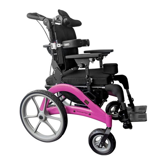
CONVAID USER’S GUIDE Flyer Standard Features Overview Full Assembly Front and Back Fig. 1 Fig. 2 Mobility Base Transit Anchor Attachment Location Seating System Docking Tubes Single Bar Foot Operated Wheel Lock 6” x 2” 12” x 2.5” (305 x 64 mm) -
Page 12: Seating Module Standard Front And Back
CONVAID USER’S GUIDE Seating Module Standard Front and Back Tilt Adjustment Lever Seating Module Back Crossbar Tilt Cable Recline Adjustment Cord Recline Lock Pins Transit Anchor Attachment Location Fig. 4 90° Removable Front Riggings Individual Fixed Footplates Safety Latch Lock on Lock Bar... -
Page 13: Seating Module With Pans
CONVAID USER’S GUIDE Seating Module with Pans H-harness Attaching Slots Height and Width Adjustable Back Seating Module Transit Anchor Attachment Location Width Adjustable Seat Pans Serial Number Label FLYER (Module) S/N: FL-P1T-00001 2017-7 85 lbs Fig. 5... -
Page 14: Flyer Specifications
CONVAID USER’S GUIDE FLYER SPECIFICATIONS (Inches/Millimeters) Model Size FL 12 FL 13 FL 14 FL 15 FL 16 Seat Width 12/305 13/330 14/356 15/381 16/406 Seat Depth Total available seat depth range is 11 - 21/279 - 533; customer to select range Options setting based on back cane position;... -
Page 15: Annex A Information Disclosure
CONVAID USER’S GUIDE FLYER SPECIFICATIONS (Inches/Millimeters) Weight Capacity Back Cane Position 1: 85 lbs/39 kg. (Transit) Back Cane Positions 2 - 4: 170 lbs/77 kg. Weight of Chair (varies 12/305 tires: 30.7 lbs/14 kg. (mobility base = 13.9 lbs/6.3 kg., seating based on tires) system with leg rest = 16.8 lbs/7 kg.) - Page 16 CONVAID USER’S GUIDE RESNA WC-1 Annex A Information Disclosure Standard Minimum Reference Disclosure Information (RESNA) Maximum Value Value Section Clause Seat Plane Angle 7.3.2 -5° 40° Effective Seat Depth 7.3.3 393. 7 mm 647 mm Effective Seat Width 7.3.4 304.8 mm 406.4 mm...
-
Page 17: Contents In The Box
Once you have all components as ordered, the directions in this User’s Guide will guide you through the process of preparing the chair for use. Convaid recommends the initial fitting, adjustments, and setup take place with the help of your Convaid Representative and/or Convaid Service Dealer. However, if the instructions contained in this user’s guide are followed carefully, a caregiver or attendant will be able to set up and assemble the... -
Page 18: Unfolding The Chair
Fig. 7 Folding/Unfolding the Seating Module The Flyer Chair can be folded into a compact mode that is ideal for transport and storage. Folding action may be limited with positioning equipment installed. Always properly secure the Flyer in a safe location when transporting as cargo In a vehicle. - Page 19 CONVAID USER’S GUIDE WARNING: Never attempt to fold the Flyer Chair with a user in it. This could result in serious injury. WARNING: Do not place user in the chair until you have verified that the folding action is properly locked.
-
Page 20: Lifting/Carrying The Seating Module
Fig. 11 Fig. 12 Fig. 13 Lifting/Carrying the Mobility Base 1. To safely lift or carry the Flyer, grasp the curved side mobility base tubes using two hands, keeping clear of wheels and accessories. Fig. 14 Fig. 14 WARNING: ALWAYS carry the seating module by the seating module backrest handle bar and the seating module’s lock bar. -
Page 21: Installing Seating Module Onto Mobility Base
CONVAID USER’S GUIDE Installing Seating Module onto Mobility Base 1. Ensure wheel lock is engaged. 2. Adjust seat back angle to upright 90 degrees position by pulling on the recline cord and adjusting the seat upright. Fig. 15 3. Carefully lift the seating module using both hands, with one hand holding the seating module’s upper back, and with the other hand holding the seating module’s lock bar, located on the bottom... -
Page 22: Removing Seating Module From Mobility Base
CONVAID USER’S GUIDE WARNING: Check proper seat module docking before placing user in chair. Check docking by lifting front seat pan up and down to ensure seating module does not disengage from mobility base. WARNING: Before placing user in the chair, make sure wheel locks are engaged. -
Page 23: Fitting Guide
User’s Guide to see if one or more of our accessories would help to facilitate posture, or consult a healthcare professional. When properly fitted, Convaid chairs will provide years of comfortable use. As the user grows, refer back to this Fitting Guide to adjust the dimensions of the chair. -
Page 24: Seat Depth Adjustment
CONVAID USER’S GUIDE Seat Depth Adjustment Measure from the most posterior portion of the buttocks to the back of the knee. Subtract from that measurement 1-2” (25-51mm) to allow adequate clearance between the seat and the back of the knee. - Page 25 Fig. 28 WARNING: When the back cane is factory set to position 1 the total weight carried by the Flyer must never exceed 85 lbs./39 kgs. WARNING: Do not place user on the chair while seat adjustment hardware is loosened. Make sure the hardware is fully tightened before placing the user on the chair.
- Page 26 CONVAID USER’S GUIDE Fig. 30 FLYER (Module) S/N: FL-P1T-00001 2017-7 85 lbs FLYER (Module) S/N: FL-P1-00001 2017-7 85 lbs FLYER (Module) S/N: FL-P3T-00001 2017-7 170 lbs FLYER (Module) S/N: FL-P3-00001 2017-7 170 lbs Fig. 31...
-
Page 27: Seat Width Adjustment
CONVAID USER’S GUIDE Seat Width Adjustment Note: Seat width ranges from 12” - 16” (305-406 mm). Follow Fig. 32 and adjustment chart (Fig. 33) to adjust the seating module to desired width. Fig. 32 Telescoping Tubes Location... - Page 28 CONVAID USER’S GUIDE 12" 13” 14” 15” 16” Size Tube A Tube B L1 & R6 L2 & R6 L3 & R6 L3 & R5 L3 & R4 Tube C L3 & R4 L2 & R4 L1 & R4 L1 & R5 L1 &...
- Page 29 CONVAID USER’S GUIDE To Remove the Width Adjustment Bolts Use 5/32” Allen wrench and 7/16” wrench to remove any adjustment bolts. 1. Remove seating module from mobility base following instructions on page 15. 2. Remove any cushions or upholstery attached to seating module.
-
Page 30: Mobility Base Width
Note: Growth Kit will include instructions. Fig. 42 Tilt-In-Space Adjustment The Flyer is equipped with a tilt-in-space mechanism. The tilt-in-space range in the Flyer is -5º anterior to 40º posterior. To Adjust the Tilt Angle: 1. With your left hand, hold onto the back cross tube, on the back of the seat to support the weight of the user. -
Page 31: Cross Tube Adjustment On Back Canes
• Always verify that the user’s legs are stable and on the foot support. • Never place hands, feet or foreign objects into the tilt mechanism area. • Never add chair accessories that are not specifically designed for the Flyer Chair, as they may interfere with the tilt mechanism. -
Page 32: Recline Adjustment
CONVAID USER’S GUIDE Recline Adjustment The Flyer comes standard with back angle adjustment of 80º - 110º in increments of 10º. Fig. 46 Optional Feature: Recline Degrees Recline Degrees (Standard) (Option) 1. The Flyer has an additional recline option 80° - 110°... -
Page 33: Positioning Belts
WC-4-19 compliant automotive type seat belt is required when the chair is used in transport vehicles. WARNING: Positioning belts and harnesses should only be installed by a Convaid provider or healthcare practitioner. Pelvic Positioning Belts Make sure the occupant does not slide down in the wheelchair seat. -
Page 34: Back Cane Mount
CONVAID USER’S GUIDE Capped Nylon Nut Metal Flat Washer Large Coved Washer Capped Nylon Nut Large Coved Washer R82 Clip Large Length Screw R82 Clip Large Length Screw Metal Flat Washer Fig. 51 Fig. 52 Back Cane Mount BACK CANE MOUNT: To attach R82 vests and belts to the back canes, identify proper location on the back cane and install hardware in the shown order. -
Page 35: Footplate Adjustment
Fig. 55 Fig. 56 Footplate Adjustment Flyer foot support is height adjustable. To determine the correct seat-to foot support height, measure from the back of the knee to the bottom of the heel. The soles of the feet or heels should rest comfortably on top of the footplates. -
Page 36: Foot Positioners
CONVAID USER’S GUIDE To Adjust the Height on One-Piece Footplate: 1. Remove detent pins from both sides of footplate, circled in Fig. 61 2. Slide footplate up leg rest extension tube until desired height has been reached. 3. Reinsert detent pins on both sides. -
Page 37: Wheels
7.5” x 2”, 16” x 2” (optional) 191 x 51 mm, 406 x 51 mm (optional) You can upgrade, replace or reorder Flyer tires at any time. You have the option of reordering replacement standard solid tires. When ordering upgraded or replacement tires, please have the following information available: •... -
Page 38: Removal & Installation Of Rear Wheels
CONVAID USER’S GUIDE Removal & Installation of Rear Wheels To Remove the Wheels: 1. Release the wheel locks (wheel lock bar “up”) . 2. Press down on the clip near the center of the wheel hub. Fig. 70 3. Pull the wheel outward to remove it from the chair. Fig. 71 WARNING: Do not remove silver clip. -
Page 39: Head Support
CONVAID USER’S GUIDE Accessories Head Support Attaching Head Support: 1. Remove head support cover by unzipping the cover on the back side. Fig. 73 2. Using a 5/32” Allen wrench and 7/16” wrench, secure the two provided mounting Allen screws on the top center of the upper back plate. -
Page 40: Adjustable Headwing Headrest Instructions
CONVAID USER’S GUIDE Adjustable Headwing Headrest Instructions 1. Unzip the cover from the back of the headrest. 2. Slightly move the cover to reveal the silver locking screw on the plastic headrest plate. 3. Note that the locking screw of the right hand side is on the top portion of the pivot hinge. -
Page 41: Anatomic Headrest Installation
CONVAID USER’S GUIDE Anatomic Headrest Installation Installing Anatomic Headrest to Turtle Bar System: 1. Align the anatomic headrest bracket with turtle bar system. Fig. 81 2. Use 6mm Allen wrench to tighten the connecting hardware. Fig. 82 Headrest bracket Note: Do not remove the preinstalled head rest bracket. Fig. 81 Note: Universal bracket must be oriented to the position as shown in Fig. - Page 42 CONVAID USER’S GUIDE 3. Install the anatomic headrest turtle bar system into the bracket shown in Fig. 85. 4. Adjust to desired height and secure the system by tightening the securement bolt with 5mm Allen wrench. WARNING: Do not set height beyond the maximum indicated line.
-
Page 43: Adjustable Headrest Installation
CONVAID USER’S GUIDE Adjustable Headrest Installation Installing the Adjustable Headrest to Turtle Bar System: 1. Align the adjustable headrest bracket with the turtle bar system. 2. Use 6 mm Allen wrench to tighten the connecting hardware. Note: Do not remove the preinstalled headrest bracket. -
Page 44: Upper Extremity Support Surface (Tray)
CONVAID USER’S GUIDE Upper Extremity Support Surface (Tray) The trays are ideal for feeding and for trunk stabilization. They feature a safety lip and are easy to clean. 1. Depress spring button on underside of armrest until tray mount tube pops out. -
Page 45: Laterals
CONVAID USER’S GUIDE Laterals Fig. 99 To Install: Remove cushion and attach laterals using the hardware provided using a 5/32” allen wrench and 7/16” wrench. Fig. 99 Lateral Width Model Size Width Range 8.5 - 11.5 9.5 - 12.5 10.5 - 13.5 11.5 - 14.5... - Page 46 CONVAID USER’S GUIDE Lateral Height (Fixed Laterals) Lateral Height (Swing Away Laterals) Model Size Height Range Model Size Height Range 10" - 16" 8.75" - 16.75" 10" - 16" 8.75" - 16.75" 10" - 16" 8.75" - 16.75" 10" - 16"...
-
Page 47: Hip Guides
CONVAID USER’S GUIDE Hip Guides Fig. 104 To Install: To install hip guides remove cushion and existing socket button head bolt on the top of the seat pan and by unscrewing the nylon capped locknut on the bottom of the seat pan by using a 5/32” allen wrench and 7/16”... -
Page 48: Canopy Attachment
CONVAID USER’S GUIDE To Adjust: Adjust the hip guides to desired width Fig. 105, 106 by removing the hardware shown on Fig. 104 Secure the hip guides with hardware and attach seat cushion Fig. 107 Fig. 107 Canopy Attachment Adjustable Canopy: 1. -
Page 49: Oxygen Tank Holder
CONVAID USER’S GUIDE Oxygen Tank Holder How to Hang the Oxygen Tank Holder 1. Remove the two frame bolts located on the left side of the frame with 5/32” Allen wrench. Fig. 111 2. Slide the oxygen tank holder in place. Fig. 112 3. -
Page 50: Ltv Vent Holder
CONVAID USER’S GUIDE LTV Vent Holder 1. Align male dovetail bracket located on ventilator with female dovetail bracket located on LTV holder bracket. Fig. 116 2. Slide down and lock securely into bracket. Fig. 117 3. Attach ventilator. Fig. 116 Fig. -
Page 51: Ventilator/Suction/Hard Tray
CONVAID USER’S GUIDE Ventilator/Suction/Hard Tray The hard tray has two independent height settings and five independent width settings. To Install: 1. Remove fixed front riggings, or elevate elevating leg rest, depending on which the chair is equipped with. 2. Slide the tray through bottom of the chair frame. - Page 52 CONVAID USER’S GUIDE To Adjust the Width of the Tray: 1. Remove the width adjustment hardware (circled in Fig. 122 & 123) with 5/32” Allen wrench and 7/16” wrench. 2. Adjust to desired width and tighten hardware. Fig. 122 Fig. 123 Ground Clearance (for back maintenance, operating &...
-
Page 53: Transit Models
3. The wheelchair tiedowns must be securely attached to the four red anchor points on the chair. See arrows for anchor points. Fig. 124 & 125 4. The occupant restraints must include a lap and shoulder belt, secured directly to the Flyer mobility base and the vehicle. -
Page 54: Transportation Mode Instructions
Using the Flyer Chair for Transportation in Motor Vehicles The Transit Model Flyer is for transporting users in motor vehicles when it is equipped with the OPTIONAL Transit feature and used in accordance with these instructions. The chair MUST be secured in a forward-facing position with Wheelchair Tiedown and Occupant Restraint Systems (WTORS), which meets the requirements of WC-4: section 18. - Page 55 WARNING: Do not use the chair if it has been involved in a crash. In the event that your Flyer is involved in a crash, please contact the Convaid Service Dealer or Convaid Customer Service Representative in order to arrange an evaluation of your Flyer.
- Page 56 WARNING: Do not use the chair if it has been involved in a crash. In the event that your wheelchair is involved in a crash, please contact the Convaid Service Dealer or Convaid Customer Service Representative in order to arrange an evaluation of your wheelchair.
-
Page 57: Recommended Clear Zones In Vehicle
CONVAID USER’S GUIDE RECOMMENDED CLEAR ZONES IN VEHICLE Fig. 127 Top View The rear clear zone is measured from the rearmost point on an occupant’s head. The front clear zone is measured from the frontmost point on an Fig. 126 Side View occupant’s head. - Page 58 CONVAID USER’S GUIDE PREFERRED ANGLES OF FRONT AND REAR TIE-DOWN STRAPS (TOP) AND PREFERRED LOCATIONS OF FLOOR ANCHOR POINTS (BOTTOM). 30 - 45° range 45 - 60° range Side view vehicle floor - front 11.75 - 20.00 14.00 - 28.00 51.00 +/- 1.00...
- Page 59 CONVAID USER’S GUIDE FIG. 132: FRONT TIEDOWN STRAPS ANGLED AWAY FROM SIDES OF WHEELCHAIR. FIG. 133: CORRECT POSITIONS OF SHOULDER AND LAP BELT RESTRAINTS AND WHEELCHAIR TIEDOWNS. Fig. 132 Fig. 133 STANDARD METAL CLIP (FIG. 134) AT LOWER END OF SHOULDER BELT AND AT END OF OPTIONAL WHEELCHAIR-ANCHORED LAP BELT USED TO CONNECT TO PIN/BUSHING (FIG.
-
Page 60: Providing Clear Space & Padding
Annex A of WC19, may be ordered from Convaid at a nominal additional cost. To attach the lap belt to the wheelchair, secure the metal clips at the ends of the lap belt (Fig. 134) to the pin/bushing connectors located on the wheelchair’s rear securement-point brackets. -
Page 61: Using Postural Belts & Supports
CONVAID USER’S GUIDE Using Postural Belts & Supports Positioning accessories such as pelvic positioning belts, anterior trunk supports, and lateral trunk supports may be used while in transit, but are not designed to provide restraint during a crash. Postural supports and belts should therefore not be relied on for restraint in a vehicle crash and... -
Page 62: Trays & Other Wheelchair Components
CONVAID USER’S GUIDE Trays & Other Wheelchair Components WARNING: To reduce the risk of potential injury to the wheelchair user or other occupants in a motor-vehicle crash, wheelchair-mounted accessories, such as trays and respiratory equipment, must be removed and secured separately during transit. -
Page 63: Wtors Manufacturers
CONVAID USER’S GUIDE Troubleshooting Guide Troubleshooting Seat Bottom Tilt Adjustment Lever Before attaching the Seating Module to the frame, check if the Tilt Adjustment Lever cable has been correctly aligned and seated inside the adjustment barrel. To Adjust: 1. Plug the cable end into the adjustment barrel on the bottom of Seating Module. -
Page 64: Important Information
CONVAID USER’S GUIDE Important Information Maintenance, Operating & Safety Instructions • READ ALL INSTRUCTIONS BEFORE USING THE PRODUCT • ALWAYS FOLLOW THESE SAFETY INSTRUCTIONS • SAVE SAFETY INSTRUCTIONS FOR FUTURE REFERENCE • For user safety, the seat belt should be fastened at all times. - Page 65 CONVAID USER’S GUIDE IMPORTANT INFORMATION • Do not use chair after occupant has outgrown it. • Do not ignore minor malfunctions and maintain the chair in good operating condition. Monitor the wheel locks (brakes) regularly (see maintenance chart). • If and whenever possible and feasible, the rider should transfer out of the chair and into an approved vehicle seat and passenger restraint system.
- Page 66 Fig. 147 User Maintenance The following maintenance procedures should be conducted on a regular basis: examine your Convaid product visually from time to time for possible wear and tear. Teflon™ spray* should be applied to frame and moving parts to maintain easy folding and adjustment.
- Page 67 Armrests & foam • Frame • Contacting a Convaid Dealer for service or • repair*** * Use a non-toxic, hypoallergenic lubricant for all moving parts of the frame. Do NOT use WD-40 or other silicone based spray as a lubricant.
-
Page 68: Warranty
Limited Warranty Convaid warrants to the original retail purchaser of the Convaid product, that if any part thereof proves functionally defective in material or workmanship within the specified warranty period, such defective part will be repaired or replaced (at Convaid’s discretion) free of charge. Warranty service may be performed by Convaid service center or (at Convaid’s discretion) the factory.
Need help?
Do you have a question about the Flyer and is the answer not in the manual?
Questions and answers