Table of Contents
Advertisement
Quick Links
Advertisement
Table of Contents

Subscribe to Our Youtube Channel
Related Manuals for Koden CVS-705D


Summary of Contents for Koden CVS-705D
- Page 3 No part of this publication may be reproduced, transmitted, translated in any form by any means without the written permission of Koden Electronics Coo., Ltd. The technical descriptions contained in this publication are subject to change without notice. Koden assumes no responsibility for any errors, incidentals or consequential damages caused by misinterpretation of the descriptions contained in this publication.
- Page 4 Koden is not liable for damages of accompaniment (change/loss of memorized content, loss of business profit, stop of business) arisen from use or failure of our products. If the stored data are changed or lost, irrespective of causes of troubles and damages, Koden is not liable for them. ...
-
Page 5: For Your Safe Operation
CVS-705D/707D For Your Safe Operation For Your Safe Operation Symbol used in this Installation Manual The following graphical symbols are used in this manual. The meaning of each symbols shall be well understood and apply at maintenance and inspection works. - Page 6 For Your Safe Operation CVS-705D/707D Caution on location of equipment Do not install the equipment where it is excessively damp and suffers Caution from excessive water drops. Measures against static electricity The static electricity may be generated from the carpet on the floor in Caution the cabin or clothes made of synthetic fiber.
-
Page 7: Table Of Contents
1.1.3 Selection of location for installation ................... 1-1 1.1.4 Laying and connection of cables ....................1-2 1.1.5 Coordination after installation ....................1-2 Installation of CVS-705D Display unit ..................1-3 1.2.1 Desk-top installation ........................1-3 1.2.2 Flush-mount installation ......................1-5 Installation of CVS-707D Processor unit ................... 1-6 Installation of 17 inch LCD Monitor (CVS-707D) ............... -
Page 8: Contents
2.7.4 Relation of the set value between [Output Limit] and [MENU] - [Echo Adjust] - [TX Power] .. 2-7 Chapter 3 Maintenance ……………………………………………………………….3-1 Inspection ........................... 3-1 Cleaning ............................. 3-1 3.2.1 Display unit of CVS-705D/Monitor unt of CVS-707D ..............3-1 3.2.2 Transducer ..........................3-2 Fuse Replacement ........................3-2 Diagnostics of troubles ......................3-2 3.4.1 Necessary information for requesting repair ................ -
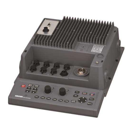
Page 9: System Configuration
CVS-705D/707D System Configuration System Configuration Connection diagram of CVS-705D Legend Standard configuration Display unit ESD-210 Option With mounting bracket and Knobs Owner supply Connector of Operation unit Operation unit CW-409-5M J1 connector External echo sounder (Owner supply) CW-371-5M CW-372-5M J2 connector... - Page 10 System Configuration CVS-705D/707D Legend Standard configuration Connection diagram of CVS-707D Option Owner supply Processor unit ESM-210 17 inch LCD Monitor* *European model: Owner supply Connector of Operation unit Operation unit CW-409-5M J1 connector External echo sounder (Owner supply) CW-371-5M CW-372-5M...
-
Page 11: Configuration Of Equipment
CVS-705D/707D Configuration of Equipment Configuration of Equipment Standard Equipment Configuration List of CVS-705D Weight/ Name of item Type Remark Length Display unit With mounting bracket and ESD-210 13 kg knobs Operation unit With mounting bracket 0.7kg/ ESO-200 CW-409-5M DC power cable... - Page 12 Configuration of Equipment CVS-705D/707D Standard Equipment Configuration List of CVS-707D Weight/ Name of item Type Remark Length Processor unit ESM-210 5.6kg Operation unit With mounting bracket 0.7kg/ ESO-200 CW-409-5M DC power cable With 5 pin connector and CW-270-2M one end plain...
- Page 13 14° × 11° Rubber mold Ship’s 10 m bottom/ φ11 Ship’s side TD-754 75kHz Ship’s 14° × 7° Rubber mold bottom/ 10 m Ship’s side φ11 Please consult a dealer of Koden or Koden about another type of transducer. 0092607052-03...
- Page 14 Configuration of Equipment CVS-705D/707D Option List Name of Item Specification Remark Weight/ Length Power rectifier PS-010 Fuse (5A) 2 pcs. AC power cable VV-2D8-3M Both ends plain. Specify Transducer CABLE_VSV- length at extension cable 2T11-White.Black order Grounding cable OW7/1.6S-3M With a 5 pin connector & a 5pin...
-
Page 15: Dimensions
CVS-705D/707D Dimensions Dimensions Display unit of CVS-705D 0092607052-03 xiii... - Page 16 Dimensions CVS-705D/707D Processor unit of CVS-707D Unit: mm (inch) 0092607052-03...
- Page 17 CVS-705D/707D Dimensions 17 inch LCD Monitor of CVS-707D 0092607052-03...
- Page 18 Dimensions CVS-705D/707D Operation unit of CVS-705D/707D Unit: mm (inch) 0092607052-03...
-
Page 19: Specifications
CVS-705D/707D Specifications Specifications Item Content Model CVS-705D CVS-707D - Display unit ESD-210 - Processor unit ESM-210 ESO-200 Operation unit Output power Dual Freq : 28,50,75,200 kHz (200 kHz is 1 kw only) Output frequency (Transducer) Single, 2 frequency, Simultaneous Output method TX rate 1500 pulses / minute at maximum (In case of single frequency, Range 2.5m and Interference rejection off) - Page 20 Specifications CVS-705D/707D - This page intentionally left blank.- xviii 0092607052-03...
-
Page 21: Chapter 1 Installation
CVS-705D/707D Chapter 1 Installation Chapter 1 Installation 1.1 Installation precautions In order to obtain the maximum performance of the echo sounder, this echo sounder should be installed by a qualified engineer in charge of installation and maintenance. Installation procedures include the following: (1) Unpacking of components. -
Page 22: Laying And Connection Of Cables
(1) Keep the transducer and power cable as far away from the cables of other electronic equipment as possible. (2) The cabinet of CVS-705D/707D Display and Processor unit shall be securely grounded to the hull, using the grounding terminal on the rear panel. -
Page 23: Installation Of Cvs-705D Display Unit
CVS-705D/707D Chapter 1 Installation 1.2 Installation of CVS-705D Display unit CVS-705D Display unit can be installed either on desk-top or flush-mounted. Install in the following procedure 1.2.1 Desk-top installation (1) Decide the location to install the Display unit and keep the space for the maintenance works as shown in Fig. - Page 24 Chapter 1 Installation CVS-705D/707D Caution: At installing on desktop, keep the maintenance space is required as shown below. Unit: mm (inch) Fig. 1.3 Maintenance space 0092607052-03...
-
Page 25: Flush-Mount Installation
CVS-705D/707D Chapter 1 Installation 1.2.2 Flush-mount installation (1) Make a square hole at the location to be installed (See Fig. 1.5) (2) Remove four plastic corner guard caps of the Display unit (These can be easily pulled out upwards). (3) Confirm that the unit matches the square hole. If not matches, correct the square hole. -
Page 26: Installation Of Cvs-707D Processor Unit
Chapter 1 Installation CVS-705D/707D 1.3 Installation of CVS-707D Processor unit CVS-707D Processor unit can be installed either on table or panel. Install by the following procedure (1) Make 4 holes at the location to be installed (See Fig. 1.6) (2) Install the Processor unit in the installing location (square hole) and fix it with 4 tapping screws (4mm) (M4 or pan-head). -
Page 27: Installation Of 17 Inch Lcd Monitor (Cvs-707D)
CVS-705D/707D Chapter 1 Installation 1.4 Installation of 17 inch LCD Monitor (CVS-707D) 17 inch LCD Monitor (CVS-707D) can be installed either on desk-top or flush-mounted. Install in the following procedure 1.4.1 Desk-top installation (1) Decide the location to install the 17 inch LCD Monitor and keep the space for the maintenance works as shown in Fig. - Page 28 Chapter 1 Installation CVS-705D/707D Caution: At installing on desktop, keep the maintenance space is required as shown below. Fig. 1.8 Maintenance space Unit:mm (inch) 0092607052-03...
-
Page 29: Flush-Mount Installation
CVS-705D/707D Chapter 1 Installation 1.4.2 Flush-mount installation (1) Make a square hole for cable at the location to be installed. (See Fig. 1.10) (2) Confirm that the unit matches the square hole. If not matches, correct the square hole. (3) Connect the connectors for power and transducer to the unit respectively. -
Page 30: Installation Of Operation Unit
Chapter 1 Installation CVS-705D/707D 1.5 Installation of Operation unit CVS-705D/707D Operation unit can be installed either on desk-top or flush-mounted. Install by the following procedure 1.5.1 Desk-top installation (1) Decide the location to install the Operation unit and keep the space for the maintenance works as shown in Fig. - Page 31 CVS-705D/707D Chapter 1 Installation Caution: On installing on desktop, keep the maintenance space is required as shown below. Fig.1.12 Maintenance space of desk-top installation Unit: mm (inch) 0092607052-03 1-11...
-
Page 32: Flush-Mount Installation
Chapter 1 Installation CVS-705D/707D 1.5.2 Flush-mount installation (1) Make a square hole at the location to be installed (See Fig.1.14) (2) Remove 4 plastic corner guard caps of the Operation unit (These can be easily pulled out upwards). (3) Confirm that the Operation unit matches the square hole. If not matches, correct the square hole. -
Page 33: Installation Of Transducer
Figure 1.15 Recommended area of transducer installation 1.6.2 Through-hull installation Transducer installation for CVS-705D/707D is only possible with through-hull installation. Various types of rectifying tanks (Turbulence Minimizing Enclosure) are prepared according to the material of the ship’s hull or transducer frequency used. Mount the rectifying tank to the ship’s bottom before mounting the transducer to in the rectifying tank. - Page 34 Figure 1.16 An example of through-hull transducer installation 1.6.3 Adjustments after installation Before you turn the unit on, check the following points to make sure the CVS-705D/707D operates properly. (1) Is the ship’s supply voltage and current within the rated range? (2) Is the transducer wiring normal? No wrong connections, no short circuits, etc.?
-
Page 35: Wiring
CVS-705D/707D Chapter 1 Installation 1.7 Wiring 1.7.1 Connection of cables to Display and Processor unit Connect the power cable and cables from the transducer to the connectors on the Display and Control unit. ●Operation unit connection *Only for CVS-707D Input/output ●External monitor output... - Page 36 Chapter 1 Installation CVS-705D/707D Pin assignment of rear connectors Pin assignment viewed from the rear of Display unit / Processor unit: 1 : R POWER 2 : R-GND 3 : G 1 : Power - 4 : G-GND 2 : Power +...
- Page 37 Fig. 1.19 Pins assignment of rear connector-2 : The external monitor connector (D-Sub 15 pin) is available only for CVS-707D. In case an external monitor is connected to CVS-705D, use the J5 connector. (Refer to P1-24 “Connection of External Monitor”)
- Page 38 After soldering is completed, be sure to provide the connected part with water resistance and insulation using self adhesive tape, etc. 2) Connect CW-836-3M after the above processing to J7 connector of CVS-705D/707D. Connect CW-844-3M after the above processing to J6 connector of CVS-705D/707D.
- Page 39 The ferrite transducer should be connected to the resonance capacitor. Transducer Capacitance value 0.1μF and 0.022μF (Parallel connection) TD-286 0.1μF TD-506F 0.1μF TD-284 0.047μF TD-504F Caution: Please consult a dealer of Koden or Koden about another type of transducer. 0092607052-03 1-19...
- Page 40 Chapter 1 Installation CVS-705D/707D In the case of connection via the junction box (JB-34): 1) Connect CW-836-3M to the junction box (JB-34). 2) Connect CW-836-3M to J7 connector of CVS-705D/707D. Short bar Black Shield White CW-836-3M Green To J7 connector of...
- Page 41 CVS-705D/707D Chapter 1 Installation 3) Connect the transducer and the junction box (JB-34). In case of TD-286* and TD-506F* Cable of the transducer is configured as shown in Fig. 1.23. Low frequency transducer TD-286 Green Black Black Shield ゙...
- Page 42 Chapter 1 Installation CVS-705D/707D In case of TD-506F and TD-66 Cable of the transducer is configured as shown in Fig. 1.24. Low frequency transducer TD-506F Green Black Black Shield ゙ Shield ゙ Red White White CW-836-3M Green Black High frequency Shield ゙...
- Page 43 It is likely to observe mutual interference when the transmit frequency of an external echo sounder and CVS-705D/707D is the same or close. Interference can be decreased by synchronizing the CVS-705D/707D transmission with the trigger of the external echo sounder. Refer to the following for the connection.
- Page 44 Chapter 1 Installation CVS-705D/707D Connection of External Monitor (J5) [Owner supply] When installing an external monitor (XGA monitor, analog RGB input), connect it via CW-576-0.5M to J5 connector. Refer to the illustration below for the wiring. After soldering, perform the waterproof and insulation treatment on the junction with a self-fusing tape.
- Page 45 Chapter 1 Installation Connection of CCD camera (J4) [Owner supply] CVS-705D/707D and a CCD camera (NTSC/PAL/SECAM) can be connected via CW-405-0.3M (option). Connect the video output terminal (RCA plug; yellow in most cases) of your CCD camera. Perform the waterproof treatment on the junction of the RCA terminal with a self-fusing tape.
- Page 46 Caution : Connect/disconnect the USB memory and the SD card after turning power supply OFF. Caution : Please use the USB memory and the SD card KODEN recommends. If the other device than recommended is used, KODEN does not assure operation.
-
Page 47: Connection Of Hemisphere V102 Gps Compass / Comnav Vector G1 Gps Satellite Compass
CVS-705D/707D Chapter 1 Installation 1.8 Connection of Hemisphere V102 GPS Compass / ComNav Vector G1 GPS Satellite Compass This is to describe the connection of Hemisphere V102 GPS Compass / ComNav Vector G1 GPS Satellite Compass used as GPS compass and Heaving sensor. - Page 48 Caution: Wind the insulation tape around the unused lead wire to prevent core wires from contacting each other. 2) Connect CW-376-5M to J3 connector of CVS-705D/707D (NMEA terminal with 12V power supply) after soldering with Port A. 3) Connect CW-376-5M to NMEA terminal of Radar after soldering with Port C when connecting with Radar as GPS compass.
- Page 49 Hemisphere V102 GPS Compass / ComNav Vector G1 GPS Satellite Compass Accessory cable Port C Port A CW-376-5M CW-376-5M Connect to NMEA terminal of the Radar. Connect to J3 of CVS-705D/707D. CVS-705D/707D Radar Plotter CW-410-5M Connect J8 of CVS-705D/707D and NMEA terminal of the Plotter.
- Page 50 Hemisphere V102 GPS Compass / ComNav Vector G1 GPS Satellite Compass Accessory cable Port C Port A CW-376-5M CW-376-5M Connect to NMEA terminal of the Plotter. Connect to J3 of CVS-705D/707D. CVS-705D/707D Plotter, 38400bps compliant The general connection chart 2 1-30 0092607052-03...
- Page 51 Hemisphere V102 GPS Compass / ComNav Vector G1 GPS Satellite Compass Accessory cable Port C Port A Unconnected. CW-376-5M Connect to J3 of CVS-705D/707D. CVS-705D/707D Plotter CW-410-5M Connect J8 of CVS-705D/707D with NMEA terminal of the Plotter. Caution: Please use the cable of which the shield wire and the chassis earth are not connected.
-
Page 52: Setting Of Hemisphere V102 Gps Compass / Comnav Vector G1 Gps Satellite Compass
Hemisphere V102 GPS Compass / ComNav Vector G1 GPS Satellite Compass needs to be initialized to generate output data as GPS compass and Heaving sensor. This can be done by setting by CVS-705D/707D. Hereafter, Hemisphere V102 GPS Compass / ComNav Vector G1 GPS Satellite Compass is referred to as “V102 GPS Compass”. - Page 53 CVS-705D/707D Chapter 1 Installation 3) Press [ ] of The setup box of [GPS Select] will be displayed. 4) Press [▲] and [▼] keys, and select [V102] or [Vector G1]. 5) Press to return the [Basics] . 6) Select [Basics] - [GPS Initialize].
- Page 54 These steps complete the setup as follows: The baud rate of NMEA2 (J3) of CVS-705D/707D is set to 38400bps. The baud rate of Port A of V102 GPS Compass is set to 38400bps, and Heaving data output is generated.
- Page 55 Chapter 1 Installation 2. This is to setup the output to the equipment to be connected on the NMEA1 (J8) ports of CVS-705D/707D. This is to set baud rate of J8 port. Transmission rate shall match the externally connected equipment.
- Page 56 Chapter 1 Installation CVS-705D/707D This is to select output data of NMEA1. Output data shall match the externally connected equipment. 1) Select [NMEA1] - [XXX Output]. 2) Press [ ] of The setup box of [XXX Output] will be displayed.
- Page 57 4800bps NMEA GPHDM GPHDT GPVTG sentence TX interval 0.1sec 0.1sec 1sec The Hemisphere V102 GPS Compass / ComNav Vector G1 GPS Satellite Compass setting after initialization by CVS-705D/707D Port A Baud rate 38400bps NMEA GPGGA GPVTG GPZDA GPHDT GPHEV GPHPR...
-
Page 58: List Of Input/Output Sentences
Chapter 1 Installation CVS-705D/707D 1.9 List of input/output sentences 1.9.1 Input sentence The sentences of GGA, GLL, HDT, MTW, MWV, MWD, RMC, VHW, VTG and ZDA can be received. Possible input formats are: NMEA0183 Ver.1.5, Ver.2.0 and Ver.3.0 Information Priority Order of sentence... -
Page 59: Chapter 2 Adjustment
CVS-705D/707D Chapter 2 Adjustment setup box of [TD Selection] will be Chapter 2 Adjustment displayed. 2.1 Setup of transducer The frequency and beam angle etc. per transducer will be conformed to those of the transducer to be used, then, the correct information can be provided. -
Page 60: Setup Of Type Of Low Frequency Transducer
Chapter 2 Adjustment CVS-705D/707D 2.1.2 Setup of type of low frequency When [Others2] is selected, two high-frequencies and two low-frequencies transducer can be set up. TD Setting – LF TD Type 6. Press [▲] or [▼] to select the type of Select the type of transducer to be actually transducer to use. -
Page 61: Setup Of Frequency For Low Frequency Transducer
CVS-705D/707D Chapter 2 Adjustment 4. Press [▲] or [▼] to select [Frequency]. TD Setting – LF TD2 Setting 5. Press [ ]. 1. Press The setup box of [Frequency] will be 2. Select [TD Setting] – [LF TD2 Setting]. displayed. -
Page 62: Setup Of Beam Angle For Low Frequency Transducer
Chapter 2 Adjustment CVS-705D/707D 5. Press [ ]. 4. Set as the same way as [HF TD1 Setting]. The setup box of [Beam Angle] will be 5. Press to close the menu. displayed. Caution: The setup of beam angle is... -
Page 63: Setup Of Bottom Limit Lf
CVS-705D/707D Chapter 2 Adjustment 2.6 Setup of Gain (TD) for transducer Correct – Gain (TD) 4. Press [▲] and [▼] to set a depth. The insufficient gain due to ultrasonic signal attenuation can be corrected. Accuracy of 5. Press to close the menu. -
Page 64: Setup Of Output Limit For Transmitter
Chapter 2 Adjustment CVS-705D/707D 2.7.1 Display of Output Limit Menu This part is lighted red or green 1. If the power supply is ON, turn OFF the power supply by long press of the key. 2. Press key, while keeping... -
Page 65: Setup Of Output Limit Lf
CVS-705D/707D Chapter 2 Adjustment 2.7.3 Setup of Output Limit LF 1. Please display the [Spc. Adj.] at the bottom of the submenu list.(Refer to 2.7.1 Display of Output Limit Menu) 2. Press Select [Spc. Adj.] - [Output Limit LF]. 3. Press [ ] of The setup box of [Output Limit LF] will be displayed. - Page 66 Chapter 2 Adjustment CVS-705D/707D - This page intentionally left blank.- 0092607052-03...
-
Page 67: Chapter 3 Maintenance
3.2 Cleaning 3.2.1 Display unit of CVS-705D/Monitor unit of CVS-707D Contamination on the screen may cause faint images. For cleaning the screen, wipe it with soft and clean cloth dipped in diluted neutral detergent. Pay full attention as the screen gets scratched easily. -
Page 68: Transducer
Chapter 3 Maintenance CVS-705D/707D 3.2.2 Transducer In the case of the through-hull installation, check the surface of opening of transducer (portion from which the ultra-sonic is emitted). If shells or oil adhere, scrub the surface with a wooden or bamboo knife with caution not to damage the surface and remove stuck materials. If you scrub strongly, the surface will be damaged, resulting in deteriorated performance of transducer. -
Page 69: Diagnostics
CVS-705D/707D Chapter 3 Maintenance screen will change in color. The same key is 3.4.2 Diagnostics pressed subsequently, the System Test As self diagnostics, panel test and LCD test screen will end and the setup box of [System can be performed. -
Page 70: Lcd Test
Chapter 3 Maintenance CVS-705D/707D range, alarm will sound and an alarm The setup box of [Initialize] will be message will be displayed. displayed. When the voltage falls in abnormal range, the indication will be in red. (8) [TEMP] displays water temperature of the water temperature sensor. - Page 71 CVS-705D/707D Chapter 3 Maintenance updated. Turn ON the power again.” will 3. Press [ ] of be displayed. The setup box of [System Program Load] 9. Press for about 5 seconds to switch will be displayed. off the power. Caution: When program updating failed on the way, switch off the power once and switch on again.
-
Page 72: If You Suspect A Failure
Chapter 3 Maintenance CVS-705D/707D 3.5 If you suspect a failure Symptom Possible cause of trouble Measure Fuse is blown. Replace the fuse (See “3.3 Even with power on, Power voltage is out of Fuse Replacement”, page nothing is displayed.
Need help?
Do you have a question about the CVS-705D and is the answer not in the manual?
Questions and answers