Koden CVS-128 Operation Manual
Color echo sounders
Hide thumbs
Also See for CVS-128:
- Operation manual (84 pages) ,
- Supplement and change of the operation manual (15 pages) ,
- Quick reference (2 pages)
Table of Contents
Advertisement
Quick Links
Download this manual
See also:
Operating Manual
Advertisement
Table of Contents

Related Manuals for Koden CVS-128


Summary of Contents for Koden CVS-128
- Page 1 COLOR ECHO SOUNDER CVS-128 CVS-128.OM.E 0093112802-01...
-
Page 3: Declaration Of Conformity
Declaration of Conformity (As referred to in Annex IV 2. of Directive 2004/108/EC) Declares under his sole responsibility that the produced Echo Sounder manufactured by Koden Electronics Co., Ltd. 5278 Uenohara Uenohara-Shi Yamanashi-Ken 409-0112, Japan Telephone +81 554 20 5865... -
Page 4: Document Revision History
Koden Electronics Co., Ltd. The technical descriptions contained in this publication are subject to change without notice. Koden assumes no responsibility for any errors, incidentals or consequential damages caused by misinterpretation of the descriptions contained in this publication. - Page 5 Important Notice CVS-128 Important Notice • The re-use and transcription of Operation Manual (hereafter called this manual) needs permission of our company. Our company prohibits the un-authorized re-use and transcription. • If this manual is lost or damaged, consult our dealer or our company.
-
Page 6: For Your Safe Operation
CVS-128 For Your Safe Operation For Your Safe Operation Pictorial used in this Instruction Manual This Operation Manual uses the following pictorials. Understand the meaning of each pictorial and implement the maintenance and inspection. Symbol Meaning Mark for warning This symbol denotes that there is a risk of death or serious injury when not dealing with it correctly. - Page 7 For Your Safe Operation CVS-128 Caution on location of equipment Do not install the equipment where it is excessively damp and suffers from excessive water drops. Escaping from static electricity The static electricity may be generated from the carpet on the floor in the cabin or clothes made of synthetic fiber.
-
Page 8: Table Of Contents
How to use the key ....1-1 Use of 【F1】/【F2】 key ..1-12 How to remove the hard cover... 1-2 Selecting the When removing the CVS-128 【F1】/【F2】 key....1-12 Display unit ........ 1-2 Preset of【F1】/【F2】key ..1-13 The clean of CVS-128 Operation of VRM .... - Page 9 Contents CVS-128 Setting of Zoom Range ....2-4 Change the display color of echo Setting of Zoom Start ....2-4 sounder image ......2-15 Setting of Background Color ..2-5 Change the depth value ...2-15 2.10 Setting of White Line ....2-5 Display the water temp graph / 2.11 Preset of Range ......2-5...
- Page 10 CVS-128 Contents Local time Offset ......3-3 Wiring......... 5-8 GPS select ......... 3-3 Connection of Cable to CVS-128 GPS initialize......3-3 Display unit ........ 5-8 Maintenance Menu ....3-4 Pin Assignment of Rear Simulation ........3-4 Connector ........5-8 Slide show........3-4 Connection of Power Cable ..
-
Page 11: Introduction
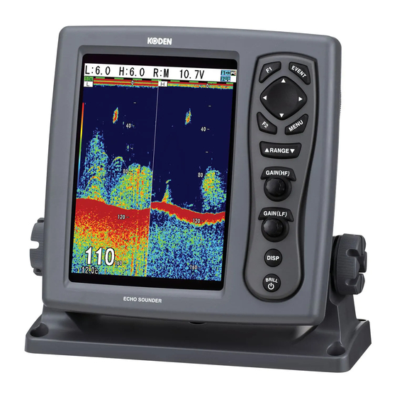
Introduction CVS-128 Introduction The CVS-128 is a Dual frequency (50 kHz/200 kHz) Color LCD display echo sounder. This unit equipped with digital process displays the circumstance in the water under all conditions, matching with the high luminance 8.4 inch LCD. -
Page 12: System Configuration
CVS-128 System Configuration System Configuration Legend Connection Diagram CVS-128 Display unit Standard configuration With mounting bracket and hard cover Option Prepared by a user To External monitor connector (J7 connector) External monitor (Prepared by a user) To Transducer connector To POWER connector CW-576-0.5M... -
Page 13: Configuration Of Equipment
Configuration of Equipment CVS-128 Configuration of Equipment Standard Equipment Configuration List Weight/ Name of item Type Remark Quantity Length Display unit 600 W/1 kW output CVS-128 with mounting bracket 3.2 kg and knob Hard cover E57MB11060 250 g DC power cable... - Page 14 CVS-128 Configuration of Equipment Type of transducer Specification Frequency Material / Mounting method Beam width Length of (Right and left x back and the cable forth) TD-500T-2B 50kHz Inner-hull Plastic 50/200 kHz 50°x50° ( -6dB) (The inner-hull kit is 600 W 200kHz needed.)
-
Page 15: Chapter 1 Basic Operation
Chapter 1 Basic Operation Chapter 1 Basic Operation 1.1 How to use the key CVS-128 Display unit In addition, for your convenience when operating keys other than keys in the menu by the [MENU] key, the menu displayed automatically closes. -
Page 16: How To Remove The Hard Cover
Claw When removing CVS-128 Display unit To prevent dust from entering, cap the connector at the rear of CVS-128 Display unit and the power cable with caps. Install the supplied cap to the transducer cable as shown in the figure and cap it. -
Page 17: Power On/Off
CVS-128 Chapter 1 Basic Operation Explanation of the display: 1.2 Power On/Off Function icon Rainbow pattern Power on Alarm icon Time mark Event icon Range Gain Press the [BRILL ] key to power on. The startup menu is displayed. When started up, the memories (ROM, RAM) are automatically checked. -
Page 18: Lcd Brilliance Adjustment
Chapter 1 Basic Operation CVS-128 Disp 1.3 LCD Brilliance Adjustment NAV1 Normal (H) Adjustment of LCD Brilliance Zoom (H) Dual Freq The brilliance of the display can be adjusted to Zoom (L) facilitate visualization. Normal (L) The [Lcd brill] and [Panel brill] can be switched NAV2 every time when pressing the [BRILL ] key. -
Page 19: Dual Frequency
CVS-128 Chapter 1 Basic Operation Dual frequency Low frequency image High frequency image The High frequency image can be displayed in the right half side and the Low frequency image can be displayed in the left half side. Since the beam width differs depending on frequency, the schools of fish and sea bottom look different. - Page 20 Chapter 1 Basic Operation CVS-128 The display width of zoom (1) Bottom is displayed in orange. Normal image Zoomed range 30.0 Zoom image (2) Bottom Discrimination The display width of zoom is displayed in orange. Normal image Zoomed range 30.0...
-
Page 21: Navigation Menu (Nav1, Nav2)
CVS-128 Chapter 1 Basic Operation The display width of zoom is displayed in orange. (4) Bottom Zoom Normal image Zoomed range 30.0 Zoom image The image below the bottom is not zoomed. (5) Bottom Follow Zoom The display width of zoom is displayed in orange. -
Page 22: Switch-Over Of Range
Chapter 1 Basic Operation CVS-128 Setting the range switching to Manual 1.5 Switch-over of Range range The range can be manually selected: The range of measured depth displayed on the display can be changed. Press [▲] or [▼] key of [▲RANGE▼]. -
Page 23: Selecting The Auto Gain
CVS-128 Chapter 1 Basic Operation Caution: When only high frequency is Selecting the manual gain displayed, no gain adjustment at low Adjustment of gain can be done manually. frequency is available. When only low frequency is displayed, no gain Press [GAIN (HF) Knob] twice, and [Gain adjustment at high frequency is select] is displayed. -
Page 24: Use Of [Event] Key
Chapter 1 Basic Operation CVS-128 Press the [MENU] to close the menu. Preseting the destination The present set value of frequency (High When you find the school of fish or tide, its frequency or Low frequency) adjusted last is location can be preset as a destination. -
Page 25: Store The Image
CVS-128 Chapter 1 Basic Operation Store the image When you find the schools of fish, its location can be stored as a destination. (10 locations at maximum) When storing the image, switch [NAV] → [EVENT Key set] → [Store pos]. (See [1.7 Use of [EVENT] key. -
Page 26: Fishing Hot Spot
Chapter 1 Basic Operation CVS-128 Fishing hot spot Leads you back to your favorite fishing hot spots or other previously stored positions in memory with input from optional GPS sensor. (See [2.13 Preset/ WPT edit/ WPT delete of Destination]) To perform the fishing hot spot, it is necessary to select [System] →... -
Page 27: Preset Of [F1] / [F2] Key
CVS-128 Chapter 1 Basic Operation Preset of [F1] / [F2] key Press the [MENU] key. Select [System] → [F1 key set] or [F2 key Marker Depth set]. (Press the [ ] key or [ ] key or [ ] key.) (See [2.1 How to operate the menu]) 20.0... -
Page 28: Display Of Fish Information
Chapter 1 Basic Operation CVS-128 Selecting the symbol info 1.10 Display of fish information [Symbol info] is effective only when [Fish symbol] is displayed. Specific response can be displayed as [Fish symbol]. Press the [MENU] key. For detection of fish information, 2 frequencies, 200 kHz and 50 kHz are used. - Page 29 CVS-128 Chapter 1 Basic Operation Points to note in use of fish symbol The values displayed by this function may be incorrect depending on various environmental conditions. In use of these values, please understand the following factors of error, and use them as reference: 【Factors of error】...
-
Page 30: Chapter 2 How To Use The Menu
CVS-128 Chapter 2 How to use the menu Chapter 2 How to use the menu 2.1 How to operate the menu Adjust Shift D.range BTM. Zoom type Disp Zoom range 10.0m Display the menu/Stop the display of Alarm1 Zoom start... -
Page 31: Changing Of Image Speed
Chapter 2 How to use the menu CVS-128 To select the menu name of other, press 2.3 Rejection of Interference the [ ] key. The cursor returns to the menu column. Interference Rejection Press the [MENU] key to close the menu. -
Page 32: Color Rejection Of Weak Echo
CVS-128 Chapter 2 How to use the menu Press the [MENU] key to close the menu. 2.4 Color Rejection of Weak Echo 2.6 Setting of Shift Color Rejection The [Shift] (Manual Shift) and [Auto Shift] are The color of weak echo can be rejected. -
Page 33: Setting Of Auto Shift
Chapter 2 How to use the menu CVS-128 (Setting: m: 2.5 to 200, fm, I.fm: 2.5 to 150, Setting of Auto Shift ft:10.0 to 650) The image is automatically shifted so that the bottom is always displayed. Press [▲] of [▼] key of [▲RANGE▼]. -
Page 34: Setting Of Background Color
CVS-128 Chapter 2 How to use the menu How to operate the menu]) Press the [ ] key. Change the set value of [Zoom start]. (Press the [ ] key or [ ] key) Zoom start White line 0~800 Press the [MENU] to close the menu. -
Page 35: Setting Of Alarm
Chapter 2 How to use the menu CVS-128 [ ] key) [Water temp alarm] issues when the water temp is within or out of the set range. It is convenient to keep the specific water temp region. (Setting: Adjust Prev - 5 to 45 ℃, 23 to 113 ºF) -
Page 36: Setting The Alarm
CVS-128 Chapter 2 How to use the menu Setting the alarm Confirm the alarm state Adjust Bottom alarm D.range The set state of [Bottom alarm] and [Fish alarm] Upper depth can be confirmed on the bar at the right corner... -
Page 37: Preset/ Wpt Edit/ Wpt Delete Of
Chapter 2 How to use the menu CVS-128 2.13 Preset/WPT edit/WPT Cancel the NAV delete of Destination The NAV started can be canceled halfway. Press the[MENU] key NAV Start Select [NAV] → [NAV cancel]. (See [2.1 How to operate the menu]) The NAV can be started by selecting the destination from the destination list. -
Page 38: Delete The Destination
CVS-128 Chapter 2 How to use the menu Select [NAV] → [WPT delete]. key. (Character: A ~ Z, blank, 0 ~ 9, +, -./) (See [2.1 How to operate the menu]) Press the [ ] key. Select the list number of destination to be deleted from the [WPT delete]. -
Page 39: Store/Recall/Deletion Of Image
Chapter 2 How to use the menu CVS-128 2.14 Store / Recall / Deletion of Image recall Image Comment P IC 0 0 0 0 1 P IC 0 0 0 02 Store the image P IC 0 0 0 03... -
Page 40: Delete The Stored Image
CVS-128 Chapter 2 How to use the menu Image recall Select the [Yes] in the confirmation menu. Comment P I C 0 0 0 0 1 Image delete P I C 0 0 0 02 P I C 0 0 0 03... -
Page 41: Selection Of Zoom
Chapter 2 How to use the menu CVS-128 Select the comment position with the [ ] 2.16 Selection of NAV Display key or [ ] key. Selection of NAV Display Image comment Comment The information can be displayed on the NAV display (NAV 1, NAV2). -
Page 42: Selection Of Nav Menu
CVS-128 Chapter 2 How to use the menu 2.17 Explanation of Sonar Selection of NAV Menu Press the [DISP] key. Switch-over of Sona-tone Select the [NAV1] or the [NAV2]. (Press the [ ] key or [ ] key) The sona-tone can be outputted to the built-in speaker by selection. -
Page 43: Explanation Of Menu Item
Chapter 2 How to use the menu CVS-128 2.18 Explanation of Menu Item The TVG adjusts the difference of strength between echoes reflected from the shallower The various items in the menu are explained. depth and echoes reflected from deeper depth so that the reflection can be uniformed. -
Page 44: Change The Display Color Of Echo Sounder Image
CVS-128 Chapter 2 How to use the menu Press the [MENU] key Change the display color of echo Select the [Adjust] → [TX power]. (See [2.1 sounder image How to operate the menu]) The [Monochrome], [8 color], [16 color] and [64 Press the [ ] key. -
Page 45: Setting Of The Background Color Of
Chapter 2 How to use the menu CVS-128 display width can be changed. Select the swap state. (Press the [ ] key or [ ] key) Press the [MENU] key. Press the [MENU] key to close the menu. Select the [D.range] → [Disp. width]. -
Page 46: Chapter 3 How To Use The Menu2
CVS-128 Chapter 3 How to use the menu2 Chapter 3 How to use the menu2 3.1 Display of Menu 3.2 Setting of External Input / Output After powering on, besides the menu displayed first with the [MENU] key, the system menu, of Set the setting related to the input/output. -
Page 47: Nmea Monitor
Chapter 3 How to use the menu2 CVS-128 NMEA Monitor 3.3 Setting of Correct Item The external input data can be displayed. To return to the original menu, press the [MENU] Prev Draft set key. 0.0m In out Sonic speed... -
Page 48: Setting Of Basic Set Item
CVS-128 Chapter 3 How to use the menu2 3.4 Setting of Basic Set Item GPS initialize It is valid only when KODEN GPS is connected. The GPS sensor is initialized. Prev English Language In out NM,kn Range&Speed unit Caution: When connecting the GPS... -
Page 49: Simulation
Chapter 3 How to use the menu2 CVS-128 3.5 Maintenance Menu All stored image deletes All stored image lists can be deleted. Prev Simulation In out Slideshow Correct Initialize Setting System check Maintain All WPTs:DLT All IMG DT:DLT Return Simulation When the [Simulation] is set to ON, the pseudo image of echo sounder is displayed. -
Page 50: Chapter 4 Maintenance And Inspection
Item Content of Inspection Connector at the rear of Check the looseness. CVS-128 Display unit Wiring of cables Check the wiring of cables connecting the equipment and the damage of cable. Grounding of display unit Scrape the rust off the ground terminal and make its contact well. -
Page 51: Fuse Replacement
Chapter 4 Maintenance and Inspection CVS-128 4.3 Fuse Replacement Use the specified fuse. If you use a fuse other than Warning specified one, it may lead to a serious accident. If the input voltage is too high, the over-current flows or a trouble occurs inside, the fuse will blow out. -
Page 52: Diagnostic Test
CVS-128 Chapter 4 Maintenance and Inspection 4.5 Diagnostic Test Perform the operation diagnosis. Confirm the version When checking the operation diagnosis of ③ displays the information on the version of panel key, the state of sensor inside and the software. -
Page 53: Chapter 5 Installation
Chapter 5 Installation 5.1 Item of Caution on Installation To exercise fully the performance of echo sounder, the installation of CVS-128 must be performed by an engineer who is officially authorized by our company. The installation work includes the following content. -
Page 54: Laying And Connection Of Cable
(1) Keep the transducer and power cable as far away from the cables of other electronic equipment as possible. (2) The cabinet of CVS-128 Display unit is securely grounded to the hull, using the ground terminal on the rear panel. -
Page 55: Installation Of Cvs-128 Display Unit
CVS-128 Chapter 5 Installation 5.2 Installation of CVS-128 Display unit CVS-128 Display unit can be desk-top installed or flush-mount installed. Install in the following procedure. Desk-top Installation (1) Remove two knob bolts fixing the display unit to the bracket. (2) Remove the display unit from the bracket and place it on the stable flat place. - Page 56 Chapter 5 Installation CVS-128 Caution: When installing on the desktop, the maintenance space shown in the illustration below is required for cable lay-out, plugging-in/out of connector, fuse replacement and bolt tightening. (3 15/16) (9 29/64)) (3 15/16) Unit: mm (inch) Fig.
-
Page 57: Flush-Mount Installation
CVS-128 Chapter 5 Installation Flush-mount Installation (1) Make a square hole (220mm x 220mm) at the location to be installed. (See Fig. 5.5.) (2) Turn counter-clockwise the knob bolt fixing the display unit to the mounting bracket to loosen it, push the unit to the left side and pull the unit upward. -
Page 58: Installation Of Transducer
Chapter 5 Installation CVS-128 5.3 Installation of Transducer The standard installation of this echo sounder is shown in figure 5.6. Figure 5.6 Installation of Transducer In case of Inner-hull Using the optional inner-hull kit (MFB-04), install the transducer to the inner side of ship’s bottom. -
Page 59: In Case Of Through Hull
FRP or silicon glue. (Glue the wooden base likewise.) (7) Thread the rubber packing and fix it with the fixing nut firmly. (8) Connect the transducer cable to the connector of CVS-128 Display unit. Fixing nut Fixing nut... -
Page 60: Wiring
Chapter 5 Installation CVS-128 5.4 Wiring Connection of Cable to CVS-128 Display unit Connect the power cable and transducer to the connectors of CVS-128 Display unit. Power input 10.8~31.2VDC NMEA data input output GPS, plotter etc Sona-tone output Line output for speaker with amplifier... -
Page 61: Connection Of Power Cable
Chapter 5 Installation Connection of Power Cable Connect the power cable to the [POWER] connector and the transducer to the [J6] at the rear of CVS-128 Display unit connector. Connection of DC power cable (CW-264A-2M) 3.5 stereo jack To [POWER] connector... -
Page 62: Connection Of Transducer
Chapter 5 Installation CVS-128 Connection of Transducer At the end to the transmission/receiving cable for TD-500T-2B, TD-500T-3B and TD-501T-3B, a water proof connector with 8-core is provided. At the end to the transducer for TD-501C is plain. 1) TD-500T-2B/500T-3B/501T-3B Connect to the J6 connector on the back of the receiver display unit. -
Page 63: Connection With External Equipment
CVS-128 Chapter 5 Installation Connection with external equipment The DC power cable contains the connection cables for external equipment such as navigation equipment and KODEN GPS sensor. Color Remark Color Remark ③ ② Power input+ (with 3A fuse) White External speaker output (with ø3.5 stereo jack) -
Page 64: Connection With Speed Sensor Or Water Temperature Sensor (Option)
Chapter 5 Installation CVS-128 Connection with Speed Sensor or Water Temperature Sensor (Option) When installing the optional speed sensor or water temperature sensor, connect to the [J6] connector together with the transducer via the transducer cable (Type: CW-840-0.3M). For wiring, see the figure below. -
Page 65: Connection Of External Speaker For Sone-Tone (Prepared By A Customer)
CVS-128 Chapter 5 Installation Connection of External Speaker for Sone-Tone (Prepared by a customer) The ø3.5 stereo jack is provided to the power cable. If you connect the speaker with the amplifier to the external, you can clearly hear the sona-tone sound. -
Page 66: Serial Data
Chapter 5 Installation CVS-128 5.5 Serial Data Input Data The sentences of GGA, GLL, HDT, MTV, MWV, RMC, VHW, VTG and ZDA can be received. The type of NMEA0183 Ver.1.5, Ver.2.0 and Ver.3.0 can be inputted. Information Priority Order of Sentence... -
Page 67: Chapter 6 Table Attached
CVS-128 Chapter 6 Table Attached Chapter 6 Table Attached 6.1 Menu List The factory set value is shown by the bold and underline. 【Disp】key NAV1, Normal (H), Zoom (H), Dual freq, Zoom (L), Normal (L), NAV2 Disp 【▲RANGE▼】key Auto range, 5.0, 10.0, 20.0, 50.0, 100, 160, 300, 500, Auto shift RANGE 【GAIN(HF)】,【GAIN(LF)】... - Page 68 Chapter 6 Table Attached CVS-128 【MENU】key Image speed (2/1, 1/1, Stop, 1/1.5, 1/2, 1/2.5, 1/3, 1/3.5, 1/4, 1/4.5) Adjust IR (OFF, Weak, Strong) Color rejection (0 to 50 %: 0%) Noise rejection (0 to 10: 0) TVG (Weak, Medium, Strong)
- Page 69 CVS-128 Chapter 6 Table Attached Water temp alarm (OFF, ON (Inside), ON (Outside)) Alarm 2 Upper temp alarm (- 5 to 45.0 ℃: 20.0 ℃) Lower temp alarm (- 5 to 45.0 ℃: 15.0 ℃) Speed alarm (OFF, ON (Upper), ON (Lower))
- Page 70 Language (English, Japanese, etc) Range&Speed unit (NM,kn, km, km/h) Depth unit (m, fm, I.fm, ft) Temperature unit (℃, °F) Localtime offset (- 11.0 to 14.0: 0.0) GPS select (Others, KODEN GPS) GPS initialize (No, Yes) Maintain Simulation (OFF, ON) Slideshow (OFF, 15, 30)
-
Page 71: Specification
CVS-128 Chapter 6 Table Attached 6.2 Specification Item Content Model CVS-128 Transmission 50 kHz/200 kHz Frequency Transmission Single or alternate Method Transmission 600 W/1 kW Power Transmission 5000 times/minute at maximum Firing Times Transmission 50 µs to 3.0 ms Pulse Width Minimal 0 dBµV... -
Page 72: Appearance
Chapter 6 Table Attached CVS-128 6.3 Appearance 0093112802-01... - Page 73 CVS-128 Chapter 6 Table Attached Maintenance Space (3 15/16) (9 29/64)) (3 15/16) Unit: mm (inch) Dimension drawing of table installation Hole for installing (9 29/64) 4-4mm screw (8 21/32) Threading hole (8 5/32) Unit: mm (inch) Dimension drawing of flush-mount installation...
Need help?
Do you have a question about the CVS-128 and is the answer not in the manual?
Questions and answers
What key do I press when I power the unit up to do a Master Reset