Table of Contents
Advertisement
Quick Links
Advertisement
Table of Contents

Related Manuals for Koden CVS-1410B


Summary of Contents for Koden CVS-1410B
-
Page 2: Declaration Of Conformity
Declaration of Conformity (As referred to in Annex IV 2. of Directive 2004/108/EC) Declares under his sole responsibility that the produced Echo Sounder manufactured by Koden Electronics Co., Ltd. 5278 Uenohara Uenohara-Shi Yamanashi-Ken 409-0112, Japan Telephone +81 554 20 5860... - Page 3 Koden Electronics Co., Ltd. The technical descriptions contained in this publication are subject to change without notice. Koden assumes no responsibility for any errors, incidentals or consequential damages caused by misinterpretation of the descriptions contained in this publication.
- Page 4 Koden Electronics Co., Ltd. The technical descriptions contained in this publication are subject to change without notice. Koden assumes no responsibility for any errors, incidentals or consequential damages caused by misinterpretation of the descriptions contained in this publication.
-
Page 5: Important Notice
Koden is not liable for damages of accompaniment (change/loss of memorized content, loss of business profit, stop of business) arisen from use or failure of our products. If the stored data are changed or lost, irrespective of causes of troubles and damages, Koden is not liable for them. ... -
Page 6: For Your Safe Operation
CVS-1410B For Your Safe Operation For Your Safe Operation Pictorial used in this Operation Manual This Operation Manual uses the following pictorials. Understand the meaning of each pictorial and implement the maintenance and inspection. Symbol Meaning Mark for warning This symbol denotes that there is a risk of death or serious injury when not dealing with it correctly. - Page 7 For Your Safe Operation CVS-1410B Caution on location of equipment Do not install the equipment where it is excessively damp and suffers from excessive water drops. Escaping from static electricity The static electricity may be generated from the carpet on the floor in the cabin or clothes made of synthetic fiber.
-
Page 8: Table Of Contents
CVS-1410B Contents Contents Document Revision History ......i Setting of Auto Shift ....1-9 Important Notice ......... ii Gain Adjustment ....... 1-10 For Your Safe Operation ......iii TVG .......... 1-10 Contents ............. v Use of [EVENT] key ....1-10 Introduction .......... -
Page 9: Contents
Contents CVS-1410B Setting of Shift step ....2-3 Display the A scope / Stop the Selection of Zoom ...... 2-3 display of A scope ....2-14 Setting of Zoom Range ....2-4 Change the display color of echo Setting of Zoom Start ....2-4 sounder image ...... - Page 10 CVS-1410B Contents Display the menu ....... 3-1 Color adjust ........ 3-5 Return to the normal menu ..3-1 Image speed adjust....3-5 Setting of External Input/Output . 3-1 Bottom limit ........ 3-5 Buzzer Setting ......3-1 Sounding ........3-5 Temp Source ......3-1 Frequency Select .......
- Page 11 Contents CVS-1410B Connection of Transducer ..5-9 Connection with external echo sounder ........5-10 Connection with external navigation equipment ....5-10 Connection with Speed Sensor or Water Temperature Sensor (Option) ........5-11 Connection of External Speaker for Sona- Tone (J2) (Prepared by a customer) ..
-
Page 12: Introduction
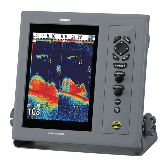
(External monitor: Prepared by a customer) CVS-1410B is the high sensitivity model with broadband transducer. This model can be used at your optimum frequencies within the specification of the broadband transducer. You can set 2 frequencies depending on a target fish or intended purpose during operation. -
Page 13: System Configuration
System Configuration CVS-1410B System Configuration Legend Connection Diagram CVS-1410B Display unit Standard configuration With mounting bracket and hard cover Option Owner supply J5 connector External monitor (Owner supply) CW-576-0.5M J2 connector External speaker (For speaker with amplifier) J6 connector (Owner supply) -
Page 14: Configuration Of Equipment
CVS-1410B Configuration of Equipment Configuration of Equipment Standard Equipment Configuration List Weight/ Name of item Type Remark Quantity Length Display unit With mounting CVS-1410B 7.5 kg bracket and knob Hard cover A30MB10250 390 g DC power cable With 5P connector... - Page 15 Configuration of Equipment CVS-1410B Type of transducer Specification Frequency Material / Mounting method Beam width Length of (Right and left x the cable back and forth) TDM-071 38kHz Urethane Ship’s bottom/ 38 to 75 kHz 30°x20° ( -6dB) mold Ship’s side...
- Page 16 CVS-1410B Configuration of Equipment Option List Name of Item Specification Remark Weight/Length For transom mounting ST-80 0.3 kg / 9 m Plastic made (with cable) For through-hull mounting Water temperature ST-90 0.6 kg / 9 m Plastic made (with cable)
-
Page 17: Change The Frequency
Change the frequency CVS-1410B Change the frequency CVS-1410B is used with the other transducer please make sure to set the below items manually in line with the transducer installed. Caution: The transducer may be damaged if the settings are wrong. - Page 18 CVS-1410B Change the frequency Adjustment of bottom detection When the bottom can't be detected or when the bottom is of mud pool or seaweed, [Gain (TD)] shall be turned up. When transfer to fish schools, etc. frequently occurs, [Gain (TD)] shall be turned down.
-
Page 19: Chapter 1 Basic Operation
Chapter 1 Basic Operation Chapter 1 Basic Operation 1.1 How to use the key CVS-1410B Display unit Various setting can be done directly. The menu list closes automatically after the key operation of the other keys than [menu]. Key Name... -
Page 20: Power On/Off
Chapter 1 Basic Operation CVS-1410B After a few seconds, the menu sets the 1.2 Power On/Off screen as selected in [DISP]. Caution: In addition to English, Japanese, Power on there are several compatible languages. Press the [BRILL ] key to power on. -
Page 21: Lcd Brilliance Adjustment
CVS-1410B Chapter 1 Basic Operation 1.3 LCD Brilliance Adjustment Disp NAV1 Normal (H) Adjustment of LCD Brilliance Zoom (H) Dual Freq The brilliance of the display can be adjusted to Zoom (L) facilitate visualization. Normal (L) The [Lcd brill] and [Panel brill] can be switched NAV2 every time when pressing the [BRILL ] key. -
Page 22: Dual Frequency
Chapter 1 Basic Operation CVS-1410B Dual frequency Low frequency image The High frequency image can be displayed in High frequency image the right half side and the Low frequency image can be displayed in the left half side. Since the beam width differs depending on frequency, the schools of fish and sea bottom look different. - Page 23 CVS-1410B Chapter 1 Basic Operation The display width of zoom (1) Bottom is displayed in orange. Normal image Zoomed range 30.0 Zoom image (2) Bottom Discrimination The display width of zoom is displayed in orange. Normal image Zoomed range 30.0...
-
Page 24: Navigation Menu (Nav1, Nav2)
Chapter 1 Basic Operation CVS-1410B The display width of zoom is displayed in orange. (4) Bottom Zoom Normal image Zoomed range 30.0 Zoom image The image below the bottom is not zoomed. (5) Bottom Follow Zoom The display width of zoom is displayed in orange. -
Page 25: Selection Of Nav Display
CVS-1410B Chapter 1 Basic Operation Selection of NAV Menu 1.5 Selection of NAV Display Press the [DISP] key. Selection of NAV Display Select the [NAV1] or the [NAV2]. (Press the [ ] key or [ ] key) The information can be displayed on the NAV display (NAV 1, NAV2). -
Page 26: Switch-Over Of Range
Chapter 1 Basic Operation CVS-1410B Setting the range switching to Manual 1.6 Switch-over of Range range The range can be manually selected: The range of measured depth displayed on the display can be changed. Press [ ] or [ ] key of [ RANGE ]. -
Page 27: Release Of Manual Shift
CVS-1410B Chapter 1 Basic Operation Select the [Auto shift] (Press [ ] of [ ] key of [ RANGE ]) Range Auto range 10.0 20.0 50.0 Press [F2] key twice. The shift function is turned on. Range Shift 40.0 Auto shift Press the [ ] key. -
Page 28: Gain Adjustment
Chapter 1 Basic Operation CVS-1410B 1.8 Gain Adjustment The TVG adjusts the difference of strength between echoes reflected from the shallower When only the image of High frequency is depth and echoes reflected from deeper depth displayed, the High frequency gain can be so that the reflection can be uniformed. -
Page 29: Selecting The Event Key Function
CVS-1410B Chapter 1 Basic Operation key. Simultaneously, the latitude and longitude of the point can be stored in the destination list. Press the [EVENT] key. When decided, the red line is drawn at the Caution: Requires position data from GPS designated location on the echo sounder sensor. -
Page 30: Store The Image
Chapter 1 Basic Operation CVS-1410B Caution: If the waypoint list is full, delete an unnecessary waypoint from the waypoint list. Store the image When you find the schools of fish, its location can be stored as a waypoint. (10 locations at maximum) When storing the image, switch [NAV] →... -
Page 31: Use Of [F1] / [F2] Key
CVS-1410B Chapter 1 Basic Operation 1.10 Use of [F1] / [F2] key F1 key set Image Speed At ex-factory, the [Image Speed] is assigned to Color Rejection the [F1] key, and the [Shift] is assigned to the Noise Rejection [F2] key. The function settable to the [F1]/[F2]... -
Page 32: Display Of Fish Information
Chapter 1 Basic Operation CVS-1410B Caution: The area where [Fish symbol] can be displayed is from 3 m to 100 m. (ft: 10 to 330, fm: 2 to 54, I.fm:2 to 60) Caution: [Fish symbol] is not displayed in Marker Depth the range that is deeper than 120m. -
Page 33: Fish Symbol Detection Adjustment
CVS-1410B Chapter 1 Basic Operation Select the information associated with [Fish Size adjustment symbol] (Press the [ ] key or [ ] key.) The indicated size of fish marks can be adjusted. Symbol info Please correct the size when the indicated value is different from the fish that actually caught. -
Page 34: Points To Note In Use Of Fish
Chapter 1 Basic Operation CVS-1410B Points to note in use of fish symbol The values displayed by this function may be incorrect depending on various environmental conditions. In use of these values, please understand the following factors of error, and... -
Page 35: Chapter 2 How To Use The Menu
CVS-1410B Chapter 2 How to use the menu Chapter 2 How to use the menu 2.1 How to operate the menu Adjust Shift step D.range BTM. Zoom type Display1 Zoom range 10.0m Display the menu / Stop the display Display2... -
Page 36: Changing Of Image Speed
Chapter 2 How to use the menu CVS-1410B (HF) Knob] or [GAIN (LF) Knob]) 2.3 Rejection of Interference To select the other menu name item, press the [ ] key. Interference Rejection The cursor returns to the menu column. The interference noise from the echo sounder Press the [MENU] key to close the menu. -
Page 37: Color Rejection Of Weak Echo
CVS-1410B Chapter 2 How to use the menu Press the [MENU] key to close the menu. 2.4 Color Rejection of Weak Echo 2.6 Setting of Shift step Color Rejection The shifting range is set by pressing the [ ] The color of weak echo can be rejected. -
Page 38: Setting Of Zoom Range
Chapter 2 How to use the menu CVS-1410B 2.9 Setting of Zoom Start Zoom type BTM. Select the zoom start in the [Zoom]. B.D. Zoom (See [1.4 Switch - over of Display mode]) B.Z. (Setting: m: 0 to 800, fm, I.fm: 0 to 500, ft: 0 to B.F.Z. -
Page 39: Easy Registration Method Of The Range
CVS-1410B Chapter 2 How to use the menu Select [Range 1 to 8]. (Press the [ ] key or [ ] key) Range1 Adjust Prev D.range Range 1 5.0 m Disp1 10.0 m When the [ ] key is pressed, it returns to... -
Page 40: Setting Of Alarm
Chapter 2 How to use the menu CVS-1410B range. (Setting: m: 0 to 800, fm, I.fm: 0 to 500, ft: 0 to 2600) It is convenient for you to judge whether the echo of school of fish is present or not. -
Page 41: Setting The Alarm
CVS-1410B Chapter 2 How to use the menu Setting the alarm Confirm the alarm state The set state of [Bottom alarm] and [Fish alarm] Adjust Bottom alarm can be confirmed on the bar at the right corner D.range Upper depth of display. -
Page 42: Preset/ Wpt Edit/ Wpt Delete Of
Chapter 2 How to use the menu CVS-1410B 2.14 Preset/WPT edit/WPT Cancel the NAV delete of Waypoint The NAV started can be cancelled halfway. Press the[MENU] key NAV Start Select [NAV] → [NAV cancel]. (See [2.1 How to operate the menu]) The NAV can be started by selecting the destination from the destination list. -
Page 43: Delete The Waypoint
CVS-1410B Chapter 2 How to use the menu key. (Character: A ~ Z blank 0 ~ 9 +, -./ Delete the waypoint Lat/Lon: 0~9 N S E W) The destination list preset in the past can be deleted. The deletion takes some time. -
Page 44: Store/Recall/Deletion Of Image
Chapter 2 How to use the menu CVS-1410B recall] list. (Press the [ ] key or [ ] key) 2.15 Store / Recall / Deletion of Image Image recall Comment P IC 0 0 0 0 1 Store the image... -
Page 45: Delete The Stored Image
CVS-1410B Chapter 2 How to use the menu Image recall Select the [Yes] in the confirmation menu. Comment P I C0 0 0 0 1 Image delete P I C0 0 0 02 P I C0 0 0 03 P I C0 0 0 04 P I C0 0 0 05 Press the [MENU] key. -
Page 46: Switch-Over Of Sona-Tone Tm
Chapter 2 How to use the menu CVS-1410B Connection of External Speaker Image comment Connect the external speaker with amplifier Comment (option) so that you can hear the sonar easily. P I C0 0 0 0 1 C0 0 0 02... -
Page 47: Change The Tx Power
CVS-1410B Chapter 2 How to use the menu TX power L: 6.0 H: 6.0 R:M 12.0V Gain (TD) L Gain (TD) H Bottom Auto Press the [MENU] key to close the menu. Caution: In [Auto] setting, it controls transmission power automatically. -
Page 48: D.range
Chapter 2 How to use the menu CVS-1410B the [ ] key or [ ] key.) expressed by the horizontal width. This expression is called [A scope]. Press the [MENU] key to close the menu. The width for strong echo is wide and the width for weak echo is narrow. -
Page 49: Display The Water Temp Graph / Stop The Display Of Water Temp Graph
CVS-1410B Chapter 2 How to use the menu Select the [Display1] → [Unit display]. (See Select the [NAV] → [NAV1 (2)]. (See [2.1 [2.1 How to operate the menu]) How to operate the menu]) Press the [ ] key. Press the [ ] key. -
Page 50: Setting Of Scale Display
Chapter 2 How to use the menu CVS-1410B Press the [MENU] key. Press the [ ] key. Select the [Display2] → [Detection area]. Select the [Image direction]. (Press the [ ] (See [2.1 How to operate the menu]) key or [ ] key) Press the [ ] key. -
Page 51: Sub Depth Value
CVS-1410B Chapter 2 How to use the menu Select the [ON] or [OFF]. (Press the [ ] changed. key or [ ] key) Press the [MENU] key. Press the [MENU] key to close the menu. Select the [Display2] [Scale type]. (See [2.1 How to operate the menu]) -
Page 52: Selecting A Display Area Of Fish Symbol Indication
Chapter 2 How to use the menu CVS-1410B To display the Freq display, select the [ON]. To stop the display of Freq display, select the [OFF]. (Press the [ ] key or [ ] key) Press the [MENU] key to close the menu. -
Page 53: Chapter 3 How To Use The Menu2
CVS-1410B Chapter 3 How to use the menu2 Chapter 3 How to use the menu2 3.1 Display of Menu 3.2 Setting of External Input / Output After powering on, besides the menu displayed first with the [MENU] key, there are the other Set the setting related to the input/output. -
Page 54: Nmea Monitor
It is likely to interfere mutually when the transmit Change to meet the usage. frequency of an external echo sounder and CVS-1410B is the same or it approaches. Interference can be decreased by transmitting Water Temp CVS-1410B synchronizing with the trigger of an external echo sounder. -
Page 55: Boat Speed
Setting the bubble time duration holds the range GPS select or shift at the level when bubble started. It selects whether the GPS sensor is the KODEN If bubble disappears and sea bottom is detected, made one or not. range or shift returns to auto mode. -
Page 56: Maintenance Menu
Chapter 3 How to use the menu2 CVS-1410B 3.5 Maintenance Menu All stored image deletes All stored image lists can be deleted. Prev Simulation In out Bottom start Slideshow Correct Initialize Setting Set up the starting depth of the seabed... -
Page 57: Setting Of Adjust2 Item
CVS-1410B Chapter 3 How to use the menu2 3.6 Setting of Adjust2 Item Prev STC strength H In out STC depth H Correct STC strength L Setting STC depth L Maintain Color adjust Adjust2 Image speed adj Bottom limit Sounding... -
Page 58: Frequency Select
Chapter 3 How to use the menu2 CVS-1410B 3.7 Frequency Select Adjust 42.0 Freq select (L) D.range Freq select (H) 210.0 Display1 Power freq adj 107.0 Display2 Return Alarm1 Alarm2 Image System Freq Next Frequency select (Low / High) The frequency of the connected transducer (low frequency and high frequency) is chosen. -
Page 59: Chapter 4 Maintenance And Inspection
CVS-1410B Chapter 4 Maintenance and Inspection Chapter 4 Maintenance and Inspection 4.1 Inspection The daily maintenance and inspection extends the life of equipment. To always keep the equipment in the best condition, implement periodically the inspection shown in the table below. -
Page 60: Fuse Replacement
Chapter 4 Maintenance and Inspection CVS-1410B 4.3 Fuse Replacement Use the specified fuse. If you use a fuse other than Warning specified one, it may lead to a serious accident. If the input voltage is too high, the over-current flows or a trouble occurs inside, the fuse will blow out. -
Page 61: Diagnostic Test
When inquiring, inform us of Ver XX.XX. To check the operation diagnosis of panel key, the state of sensor inside and the version of KM-F13 Ver.xx.xx in case of CVS-1410B software. Return to the menu Press the [MENU] key for more than 3 seconds. -
Page 62: Chapter 5 Installation
Chapter 5 Installation 5.1 Items of Caution on Installation To realize the full performance of echo sounder, the installation of CVS-1410B must be performed by an engineer who is officially authorized by our company. The installation work includes the following content. -
Page 63: Laying And Connection Of Cable
Chapter 5 Installation CVS-1410B Laying and Connection of Cable (1) Keep the transducer and power cable as far away from the cables of other electronic equipment as possible. (2) The cabinet of Display unit shall be securely grounded to the hull, using the ground terminal on the rear panel. -
Page 64: Installation Of Display Unit
CVS-1410B Chapter 5 Installation 5.2 Installation of Display unit Display unit can be installed either on desk-top or flush-mounted. Install in the following procedure. Desk-top Installation (1) Remove two knob bolts fixing the display unit to the bracket. (2) Remove the display unit from the bracket and place it on the stable flat place. - Page 65 Chapter 5 Installation CVS-1410B Caution: When installing on the desktop, the maintenance space shown in the illustration below is required for cable lay-out, plugging-in/out of connector, fuse replacement and bolt tightening. Unit: mm (inch) Fig. 5.3 Maintenance space 0093114105-03...
-
Page 66: Flush-Mount Installation
CVS-1410B Chapter 5 Installation Flush-mount Installation (1) Make a square hole at the location to be installed. (See Fig. 5.5.) (2) Turn counter-clockwise the knob bolt fixing the display unit to the mounting bracket to loosen it, push the unit to the left side and pull the unit upward. The mounting bracket and knob bolt are not used. -
Page 67: Installation Of Transducer
Chapter 5 Installation CVS-1410B 5.3 Installation of Transducer The standard installation of the transducer is shown in figure 5.6. Inner-hull kit Figure 5.6 Installation of Transducer In case of Inner-hull Using the optional inner-hull kit, install the transducer to the inner side of ship’s bottom. -
Page 68: Wiring
CVS-1410B Chapter 5 Installation 5.4 Wiring Connection of Cable to Display unit Connect the power cable and transducer to the connectors of Display unit. (J1) • External synchronous input / output External echo sounder (J2) • Sona-Tone output Line output for speaker with amplifier (J3) •... -
Page 69: Pin Assignment Of Rear Connector
Chapter 5 Installation CVS-1410B Pin Assignment of Rear Connector Pin assignment viewed from the rear of Display unit. POWER 1 Power- 1 Outside power (-) 2 Power+ 2 NMEA TX+ 3 Un-connected 3 NMEA TX- 4 Un-connected 4 NMEA RX+... -
Page 70: Connection Of Power Cable
TDM-071/TDM-091D Connect to the J6 connector on the back of the display unit. Connection of wire in transducer cable J6 connector of CVS-1410B Caution: Wind the insulation tape around the un-used lead wire for core-wires not to contact each other. -
Page 71: Connection With External Echo Sounder
Chapter 5 Installation CVS-1410B Connection with external echo sounder It is likely to interfere mutually when the transmit frequency of an external echo sounder and this echo sounder is the same or close. Interference can be decreased by synchronizing this echo sounder transmission with the trigger of the external echo sounder. -
Page 72: Connection With Speed Sensor Or Water Temperature Sensor (Option)
CVS-1410B Chapter 5 Installation Connection with Speed Sensor or Water Temperature Sensor (Option) When installing the optional speed sensor or water temperature sensor, connect to the [J6] connector together with the transducer via the transducer cable (Type: CW-840-0.3M). For wiring, see the figure below. -
Page 73: Connection Of External Speaker For Sona- Tone Tm (J2)
Chapter 5 Installation CVS-1410B Connection of External Speaker for Sona-Tone (J2) (Prepared by a customer) The ø3.5 stereo jack is provided to the CW-264A-2M cable. If you connect the speaker with the amplifier to the external, you can clearly hear the Sona-Tone sound. -
Page 74: Serial Data
CVS-1410B Chapter 5 Installation 5.5 Serial Data Input Data The sentences of GGA, GLL, HDT, MTW, MWV, RMC, VHW, VTG and ZDA can be received. The type of NMEA0183 Ver.1.5, Ver.2.0 and Ver.3.0 can be input. Information Priority Order of Sentence... -
Page 75: Chapter 6 Table Attached
CVS-1410B Chapter 6 Table Attached Chapter 6 Table Attached 6.1 Menu List The factory set value is shown by the bold and underline. [DISP] key NAV1, Normal (H), Zoom (H), Dual freq, Zoom (L), Normal (L), NAV2 Disp [▲RANGE▼] key Auto range, 5.0, 10.0, 20.0, 50.0, 100, 160, 300, 500, Auto shift... - Page 76 Chapter 6 Table Attached CVS-1410B [MENU] key Image speed (Speed1, Speed2, Speed3, Speed4, Stop, Speed5 (1/1), Speed6, Adjust Speed7, Speed8, Speed9) IR (OFF, Weak, Strong) Color rejection (0 to 50 %: 0%) Noise rejection (0 to 10: 0) TX power (20, 30, 40, 50, 60, 70, 80, 90, 100, Auto)
- Page 77 CVS-1410B Chapter 6 Table Attached Alarm 1 Bottom alarm (OFF, ON) Upper depth (0 to 800 m: 5 m) Lower depth (1 to 800 m: 50 m) Fish alarm (OFF, ON) Position (0 to 800 m: 5 m) Range (1 to 800 m: 50 m)
- Page 78 Range&Speed unit (NM, kn, km, km/h) Depth unit (m, fm, I.fm, ft) Temperature unit (°C, °F) Localtime offset (- 11.0 to 14.0: 0.0) GPS select (Others, KODEN GPS) GPS initialize (No, Yes) Maintain Simulation (OFF, ON) Slideshow (OFF, 15, 30)
-
Page 79: Specification
CVS-1410B Chapter 6 Table Attached 6.2 Specification 0093114105-03... -
Page 80: Dimensions
Chapter 6 Table Attached CVS-1410B 6.3 Dimensions Unit: mm (inch) 0093114105-03...
Need help?
Do you have a question about the CVS-1410B and is the answer not in the manual?
Questions and answers