Table of Contents
Advertisement
Quick Links
Please Read
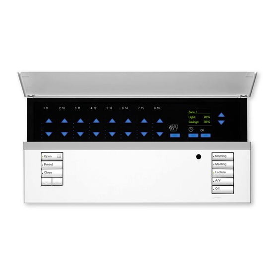
The GRAFIK Eye QS System allows for control of both lights and
shades or window treatments using a single control unit. Features
include pushbutton scene recall, info screen that displays energy
savings and status, IR receiver, astronomic timeclock, occupant
sensor connection, and backlit buttons that are easy to find and
operate.
Model Number
Unit Capacity
(watts)
QSG - 3PCE
1 500
QSG - 4PCE
2 000
QSG - 6PCE
2 300
(see page 8 for additional ratings)
All units: 230 V
50/60 Hz
R
System
LUTRON
Zone Capacity
(watts)
500
500
500
Operation Guide
Contents
Installation
Wiring the GRAFIK Eye QS System . . . . . . . . . . . . . . . . . 3
Class 2 / PELV Cable . . . . . . . . . . . . . . . . . . . . . . . . . 4
QS System Low-Voltage Control Wiring . . . . . . . . . . . . . .5
QS System Low-Voltage Terminal Connections . . . . . . . 6
Installing the GRAFIK Eye QS System . . . . . . . . . . . . . . . 7
Zone Setup . . . . . . . . . . . . . . . . . . . . . . . . . . . . . . . . . . . .8
Operation
Preprogrammed Button Functionality . . . . . . . . . . . . . . 10
General Functionality . . . . . . . . . . . . . . . . . . . . . . . . . . . 11
General Functionality: Programming Mode . . . . . . . . . .12
Zone Button Operation . . . . . . . . . . . . . . . . . . . . . . . . . .13
Quick Scene Programming . . . . . . . . . . . . . . . . . . . . . . 15
Scene Setup . . . . . . . . . . . . . . . . . . . . . . . . . . . . . . . . . .16
LED Displays for Lighting Levels . . . . . . . . . . . . . . . . . . 18
Adjusting Window Treatment Settings . . . . . . . . . . . . . .19
Timeclock Operation . . . . . . . . . . . . . . . . . . . . . . . . . . . .23
Set Save Mode . . . . . . . . . . . . . . . . . . . . . . . . . . . . . . . .28
Set Up Occupant Sensor . . . . . . . . . . . . . . . . . . . . . . . .29
Activate System Accessories . . . . . . . . . . . . . . . . . . . . .30
Faceplate Removal . . . . . . . . . . . . . . . . . . . . . . . . . . . . .30
Troubleshooting . . . . . . . . . . . . . . . . . . . . . . . . . . . . . . . .31
Menu Options . . . . . . . . . . . . . . . . . . . . . . . . . . . . . . . . .34
Warranty . . . . . . . . . . . . . . . . . . . . . . . . . . . . . . . . . . . . .35
Contact Information . . . . . . . . . . . . . . . . . . . . . . . . . . . .36
Chinese
Installation and
Advertisement
Table of Contents

Related Manuals for Lutron Electronics GRAFIK Eye QSG-3PCE


Summary of Contents for Lutron Electronics GRAFIK Eye QSG-3PCE
-
Page 1: Table Of Contents
Installation and System Operation Guide Please Read The GRAFIK Eye QS System allows for control of both lights and Contents shades or window treatments using a single control unit. Features Installation include pushbutton scene recall, info screen that displays energy Features and Functions of the GRAFIK Eye QS System . -
Page 2: Features And Functions Of The Grafik Eye Qs System
Features and Functions of the GRAFIK Eye QS System ® Hinged faceplate Space for future shade columns Info screen Zone numbers Displays status; programming functions Zone raise/lower buttons Zone LEDs display current Master buttons lighting zone levels Temporarily raise and lower lighting levels on unit Lighting column Shade column... -
Page 3: Wiring The Grafik Eye Qs System
Wiring the GRAFIK Eye QS System ® Important Wiring Information Caution! Before connecting the Caution! Do not connect line loads to the control unit, test the voltage/mains cable to Class 2 / • Use properly certified cable for all line loads for short-circuits. -
Page 4: Wiring The Grafik Eye Qs System Class 2 / Pelv Cable
Wiring the GRAFIK Eye QS System ® Class 2 / PELV USA Cable IR Wiring 1,0 mm (#18 AWG) each terminal 1: IR DATA From external 2: IR COM IR connection (by others) Occupant Sensor Wiring 1 2 3 4 5 6 L N 1,0 mm (#18 AWG) each terminal... -
Page 5: Qs System Low-Voltage Control Wiring
QS System Low-Voltage Control Wiring • System communication uses Class 2 / T-Tap Wiring Example PELV low-voltage wiring. GRAFIK Eye QS • Follow all local and national electrical codes when installing Class 2 / PELV seeTouch QS wiring with line voltage/mains wiring. LUTRON •... -
Page 6: Qs System Low-Voltage Terminal Connections
QS System Low-Voltage Terminal Connections Control units shown in rear view • Connect the terminal 1, 3, and 4 connections to all control units, wallstations, and control interfaces. • Each control unit has its own power A3 powers supply. Terminate the terminal 2 wallstations 2, connection (24 V power) so that each... -
Page 7: Installing The Grafik Eye Qs System
Installing the GRAFIK Eye QS System ® 1.Mount a 89 mm (3 1/2-in.) deep 200 mm (7.9 in.) 4-gang wallbox on a dry, flat indoor surface that is accessible and allows for system programming and operation. Allow at least 110 mm 87 mm (4 1/2 in.) clearance above and below (3.5 in.) -
Page 8: Zone Setup
Zone Setup Assign Load Type Master buttons 1. Enter programming mode (see page 12). Main menu 2. Use the master buttons to highlight “Zone button setup” and press the OK button to Occ sensor accept. Zone setup 3. Use the master buttons to highlight “Load type”. - Page 9 Zone Setup Set High End or Low End Master High and low end trim settings limit the Main menu buttons maximum and minimum output of a dimming zone. Trim levels are set Occ sensor button automatically when the load type is Zone setup programmed.
-
Page 10: Preprogrammed Button Functionality
Preprogrammed Button Functionality The GRAFIK Eye QS System controls lights without special programming. The factory ® defaults for the lighting column buttons are shown below for both dimmable and non- dim zones. See pages 15 through 17 for methods for changing scene settings. Lighting Column Button Preprogramming (Factory Default: Dimmable Loads) Scene 1: All lights to 100%... -
Page 11: General Functionality
General Functionality The info screen goes blank after 20 Info screen: see example screens below seconds if there is no button press or fading. Master buttons temporarily raise or lower The master buttons also activate the info all lights (except unaffected, shades, and screen. -
Page 12: General Functionality: Programming Mode
General Functionality: Programming Mode Entering and Exiting Programming Mode Main menu To enter programming mode: Press and hold simultaneously the top and Timeclock Master buttons bottom buttons on the lighting column for 3 Scene setup seconds.The LEDs in the lighting buttons OK button will scroll from top to bottom, confirming Info screen display... -
Page 13: Zone Button Operation
Zone Button Operation Each column of buttons represents one zone of lights. Pressing any button on a column turns on the info screen and displays the zone’s current light level and current energy savings. Pressing the raise and lower buttons on a zone causes different actions depending on zone type (see below). - Page 14 Zone Button Operation Name a Zone Master Main menu 1. Enter programming mode (see page 12). buttons 2. Use the master buttons to highlight “Zone setup” Occ sensor and press the OK button to accept. button Scene setup Zone setup 3.
-
Page 15: Quick Scene Programming
Quick Scene Programming Save Always Mode The default save mode (see page 28) is Save Always. This mode allows you to quickly set scenes on the lighting column without entering program mode. 1.Press the button for the scene you want to set;... -
Page 16: Scene Setup
Scene Setup Program a Scene Main menu 1. Enter programming mode (see page 12). 2. Use the master buttons to highlight “Scene setup” and Timeclock press the OK button to accept. Master Scene setup Scene setup 3. Use the master buttons to select “Levels” to adjust lighting buttons and/or window treatment levels. - Page 17 Scene Setup Name a Scene Master Main menu 1. Enter programming mode (see page 12). buttons 2. Use the master buttons to highlight “Scene setup” Occ sensor and press the OK button to accept. button Scene setup Scene setup 3. Use the master buttons to highlight “Labels” and press the OK button to accept.
-
Page 18: Led Displays For Lighting Levels
LED Displays for Lighting Levels Dimmable Lights Non-Dim Lights 1-17% 18-34% 35-51% 52-68% 69-85% 86-99% On/100% Unaffected (lights are not affected by scene button or master raise/lower) Legend: LED lit LED off GRAFIK Eye QS System Installation and Operation Guide 18 ®... -
Page 19: Adjusting Window Treatment Settings
Adjusting Window Treatment Settings Setting Limits 2.Select the EDU you want to to adjust using the top button on the shade Note: Entering Limit Setup mode column. Each time you press and release may cause window treatments to the top button, a different EDU that is move approximately 203.2 mm assigned to that shade column will open (8 in.)up or down. - Page 20 Adjusting Window Treatment Settings Assigning EDUs to Shade Columns - Or, press and release any button on an Note: Once you have assigned window EDU to toggle between unassignment treatments to a shade column, you will Note: Entering Assignment mode and assignment for that EDU’s window notice the following additional will cause the window treatments...
- Page 21 Adjusting Window Treatment Settings Preset Adjustment: Simple Method Preset Adjustment: Advanced Method 4.To move an EDU individually to its desired preset setting, select the EDU 1. Use the raise and lower Note: The advanced method for adjusting using the top button on the shade buttons on the shade presets is needed only if you wish to have column.
- Page 22 Adjusting Window Treatment Settings Name a Group of Window Treatments Main menu 1. Enter programming mode (see page 12). Master 2. Use the master buttons to highlight “Shade labels” and press buttons Zone setup the OK button to accept. Shade labels 3.
-
Page 23: Timeclock Operation
Timeclock Operation Set Time and Date Main menu 1. Enter programming mode (see page 12). 2. Use the master buttons to highlight “Timeclock” Timeclock Timeclock and press the OK button to accept. Scene setup Master 3. Use the master buttons to highlight “Time & date” buttons and press the OK button to accept. - Page 24 Timeclock Operation Set Location Main menu 1. Enter programming mode (see page 12). 2. Use the master buttons to highlight Timeclock Master Timeclock “Timeclock” and press the OK button to buttons Scene setup accept. 3. Use the master buttons to highlight button “Location”...
- Page 25 Timeclock Operation Add an Event Main menu 1. Enter programming mode (see page 12). 2. Use the master buttons to highlight “Timeclock” and press the OK Timeclock Timeclock button to accept. Master Scene setup 3. Use the master buttons to highlight “Add events” and press the OK buttons button to accept.
- Page 26 Timeclock Operation Delete an Event 1. Enter programming mode (see page 12). Main menu 2. Use the master buttons to highlight Timeclock Timeclock “Timeclock” and press the OK button to Scene setup accept. Master buttons 3. Use the master buttons to highlight “Delete events”...
- Page 27 Timeclock Operation Set a Holiday 1. Enter programming mode (see page 12). Timeclock 2. Use the master buttons to highlight “Timeclock” and press the OK button to Delete schedule accept. Holiday Master 3. Use the master buttons to highlight buttons “Holiday”...
-
Page 28: Set Save Mode
Set Save Mode 1. Enter programming mode (see page 12). Main menu 2. Use the master buttons to highlight “Save mode” and press the OK button to Scene setup accept. Master Save mode buttons 3. Use the master buttons to highlight the save mode you would like. -
Page 29: Set Up Occupant Sensor
Set Up Occupant Sensor 1. Enter programming mode (see page 12). Main menu 2. Use the master buttons to highlight “Occ sensor” and press the OK button to accept. Save mode Master Occ sensor 3. Use the master buttons to select the scene you wish to activate buttons when the room is occupied. -
Page 30: Activate System Accessories
Activate System Accessories Faceplate Removal Once your control unit is programmed, The faceplates may need to be removed you will need to activate any accessories to change the color or to write in zone or interfaces that are a part of the labels. -
Page 31: Troubleshooting
Troubleshooting Symptom Possible Causes Remedy Unit does not control loads Breaker/MCB is off Switch breaker/MCB on Unit does not turn lights on Long fade time Set fade time to 0 seconds LEDs on front of unit are not ON Low zone settings Reprogram scenes to a higher intensity MCB/breaker is tripping Miswire... - Page 32 Troubleshooting (continued) Symptom Possible Causes Remedy Unit does not allow scene change or Unit in wrong save mode Change to correct save mode zone adjustments Keypad in system has locked the unit Check programming and state of keypads Screen is off Normal operation Screen turns off after 20 seconds Occupant sensor input does not work...
- Page 33 Troubleshooting (continued) - Window Treatment Functions Symptom Possible Causes Remedy EDU (electronic drive unit of the window EDU is not powered Check EDU power treatment) will not move Window treatment fabric is caught on Check and unbind window treatment something fabric EDU is not assigned to a keypad Assign the EDU to a keypad...
-
Page 34: Menu Options
Menu Options Timeclock Zone setup • View events • Load type See page 26 See page 8 • Add events • High end See page 9 Copy all timeclock events from one day to another • Low end See page 9 •... -
Page 35: Warranty
(b) failure to TO THE INSTALLATION, DEINSTALLATION, USE OF OR INABILITY registered trademarks of Lutron Electronics Co., Inc. install, maintain and operate the unit pursuant to the operating TO USE THE UNIT OR OTHERWISE UNDER OR IN CONNECTION ©... -
Page 36: Contact Information
FREEPHONE 0800.90.12.18 TEL +86.10.5877.1818 FAX +55.11.3887.7138 FAX +86.10.5877.1816 Germany North and South America Technical Hotlines Lutron Electronics GmbH, Landsberger Allee 201, 13055 China, Shanghai USA, Canada, Caribbean: 1.800.523.9466 Berlin, Germany Lutron GL Ltd., Shanghai Representative Office Mexico: +1.888.235.2910 TEL +49.(0)30.9710.4590 Suite 07, 39th Floor, Plaza 66 Central/South America: +1.610.282.6701...
Need help?
Do you have a question about the GRAFIK Eye QSG-3PCE and is the answer not in the manual?
Questions and answers