
Related Manuals for golmar Nexa 90


Summary of Contents for golmar Nexa 90
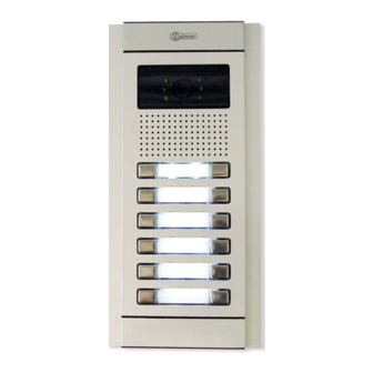
- Page 1 Cód. 50124534 Audio door entry system 4+'n' installation busy channel Nexa 90 Instructions manual T651 ML rev.0113...
-
Page 2: Table Of Contents
INTRODUCTION First of all we would like to thank and congratulate you for the purchase of this product manufactured by Golmar. The commitment to reach the satisfaction of our customers is stated through the ISO-9001 certification and for the manufacturing of products like this one. -
Page 3: System Characteristics
SYSTEM CHARACTERISTICS O Audio system with 4 + N wires installation. O For installations with several access doors. O Up to three telephones in the same apartment. O Up to 20 push buttons modules EL610. O Electronic call type with selectable call tone on EL651 sound module. O Acoustic call acknowledgement signal. -
Page 4: Door Panel Description
DOOR PANEL DESCRIPTION oor panel description. Main module Push button module Sound module , sound module with busy channel (electronic call). EL651 Push buttons electronic module EL610A , for 5 single push buttons or 10 double push buttons. Short connection cable, it is supplied with EL610A module (8 cm length). For the connection of the push buttons between the sound module EL651 and the push buttons module EL610A and between push buttons modules EL610A of the same... -
Page 5: Modules Description
MODULES DESCRIPTION ound module EL651 description. Front side. Speaker. Door panel audio adjustment. Telephone audio adjustment. Microphone. Sound module push buttons (x2). Back side. Door panel audio adjustment. Telephone audio adjustment. Push buttons connector. Installation terminals (4+N Bus and busy channel). Label. - Page 6 MODULES DESCRIPTION ush buttons electronic module EL610A description. Front side. Push buttons module (x10). Back side. Input push buttons connector. Label. Installation terminals push buttons, (call Independent). Output push buttons connector. Push buttons number. - I1 : Call ind. to push button 1. - I2 : Call ind.
- Page 7 DOOR PANEL INSTALLATION mbedding box positioning. 1850 1700 1500 The upper part of the door panel should be placed at 1,65m. height roughly. The hole dimensions will depend on the type of door panel. Door panel 90CS CEV90 Model CEA90C CEV90C 99 mm.
-
Page 8: Sound Module El651
DOOR PANEL INSTALLATION lace the embedding box. Pass the wiring through the hole made in the bottom part of the embedding box. Level and flush the embedding box. Once the embedding box is placed, remove the protective labels from the attaching door panel holes. ssembly the electronic modules. - Page 9 DOOR PANEL INSTALLATION old the frame on the embedding box. Insert the hinge that it is supplied with the product in the embedding box, as shown in the drawing. To hold the frame on the embedding box, insert the hinge in the housings arranged for this purpose in the frame, as shown in the drawing.
- Page 10 DOOR PANEL INSTALLATION lug the Short connection cable. 5 P1 3 ~2~1 CVCV Insert the short connection cable that it is supplied with the product EL610A, in the push buttons connector of the sound module EL651 and the other end of the connection cable in the input connector placed in the top part of the push buttons EL610A module, as shown in the drawing.
- Page 11 DOOR PANEL INSTALLATION inal adjustments. If after starting the system it 's considered that the audio volume isn 't correct, proceed with the necessary adjustments as shown in the drawing . lace the nameplate labels. Open the label holder. Place the label and close.
-
Page 12: Door Panel Installation
DOOR PANEL INSTALLATION oor panel assembly. In assemblies of a single door panel, it is ready from factory to be mounted. If the door panel to installing is of more than one module it will be necessary make some adjustments to join a door panel with other one. -
Page 13: Power Supply Installation
POWER SUPPLY INSTALLATION nstalling the TF-104 transformer. Install the transformer in a dry and protected place without risk of drip or water projections. To avoid an electrical shock, neither remove the primary protection cover nor handle the connected wire in the terminals. The installation and handling of these equipments must be performed by authorised personnel and without the power connected. -
Page 14: Telephone Installation
TELEPHONE INSTALLATION escription of the T-900, T-902, T-900VD, T-910 and T-910R telephones. Telephone handset. Speaker grille. Microphone hole. Subjection hole. Telephone cord connectors. Door release push button. Hook switch. Contact free additional push button. Max. 200mA / 48Vd.c. (only T-902.) To open the telephone insert a plain screwdriver into the slots and rotate it as shown. - Page 15 TELEPHONE INSTALLATION escription of the T-700, T-712VD and T-710R telephones. Telephone handset. Speaker grille. Microphone hole. Subjection hole. Telephone cord connectors. Door release push button. Contact free additional push button. Max. 200mA / 48Vd.c. (only T-712VD). Call volume regulator. (only T-712VD with electronic call). Hook switch.
-
Page 16: Installations Diagrams
INSTALLATION DIAGRAM Platea Serie 700 Telephone T-700, T-712VD and T-710R Condal Serie 900 Telephone T-900, T-902, T-900VD, T-910 0 10 5 3 P1 and T-910R Nexa 90 ind. 3 ind. 2 EL651 EL610A TF-104 Connection cable ind. 1 I1 I2 I3 I4 I5 I6 I7 I8 I9 I10... -
Page 17: Several Access Doors
INSTALLATION DIAGRAM everal access door. Electronic call. Nexa 90 EL651 EL610A TF-104 Connection cable I1 I2 I3 I4 I5 I6 I7 I8 I9 I10 I1 I2 10 5 ind. 1 Main ind. 2 ind. 3 Sections chart Terminal 100m. 300m. -
Page 18: Replacement
Note: Replace the installation of several access Serie 60 '4+n' to Nexa 60 '4+n'. If telephones are not compatible with electronic call they must be also replaced by Golmar electronic call-compatible telephones. For the connection of the Nexa 60 '4+n', (see pages 55-56). -
Page 19: Optional Connections
OPTIONAL CONNECTIONS arallel telephones installation. The maximum number of telephones placed in the same apartment is three. For each telephone placed in parallel the section corresponding to the call wire must be doubled. Electronic call. ind. TROUBLESHOOTING HINTS O Nothing operates. w Check the output transformer voltage between 'SEC' terminals: it should have 12 to 17Va.c. - Page 20 Golmar se reserva el derecho a cualquier modificación sin previo aviso. Golmar se réserve le droit de toute modification sans préavis. Golmar reserves the right to make any modifications without prior notice.
Need help?
Do you have a question about the Nexa 90 and is the answer not in the manual?
Questions and answers