Table of Contents
Advertisement
GALA SYNERGIC 5000
TECHNICAL INSTRUCTIONS MANUAL. POWER SOURCES.
GB
INDUSTRIAL MIG/MAG WELDING EQUIPMENT OF SYNERGIC CONTROL.
GB
TO HELP YOU IN YOUR WORK CAREFULLY READ THIS MANUAL.
THIS EQUIPMENT MUST BE USED BY PROFESSIONALS.
Jaime Ferrán 19 50014 ZARAGOZA (Spain)
TLF.-34/976473410 FAX.-34/976472450
GALA Synergic
5000
(3Ph - 230/400V 50/60 Hz)
Ref. 432.00.000
Ref. 43217545/Ed0
Advertisement
Table of Contents

Related Manuals for gala gar GALA SYNERGIC 5000


Summary of Contents for gala gar GALA SYNERGIC 5000
- Page 1 GALA SYNERGIC 5000 TECHNICAL INSTRUCTIONS MANUAL. POWER SOURCES. INDUSTRIAL MIG/MAG WELDING EQUIPMENT OF SYNERGIC CONTROL. GALA Synergic 5000 (3Ph - 230/400V 50/60 Hz) Ref. 432.00.000 THIS EQUIPMENT MUST BE USED BY PROFESSIONALS. TO HELP YOU IN YOUR WORK CAREFULLY READ THIS MANUAL.
-
Page 2: Table Of Contents
CONTENTS Page 1. GENERAL DESCRIPTION. TECHNICAL CHARACTERISTICS. --------------------------------------------------------------------- 3 1.1. POWER SOURCES: GALA SYNERGIC 5000. MODULAR SYSTEM. -------------------------------------------------- 3 1.2. WIRE-FEED UNIT D-24C SYNERGIC Ref. 627.00.000---------------------------------------------------------------- 4 1.3. EXTENSION CORDS. WELDING TORCHES. --------------------------------------------------------------------------- 4 1.4. COOLING MODULE WCS 510. Ref. 634.00.000 -------------------------------------------------------------------- 4 1.5. -
Page 3: General Description. Technical Characteristics
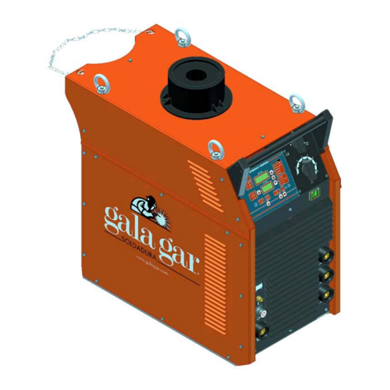
1.3 - Connection extension lead between power source and wire-feed unit. Welding torch. 1.4 - Cooling module for cooled welding gun. 1.5 Bottle support. 1.6 - Auxiliary elements: Pressure reducing valve for gas bottle, gas economiser. 1.1. POWER SOURCES: GALA SYNERGIC 5000. MODULAR SYSTEM. GALA SYNERGIC 5000 TECHNICAL CHARACTERISTICS Ref. 432.00.00... -
Page 4: Wire-Feed Unit D-24C Synergic Ref. 627.00.000
GALA SYNERGIC 5000 D-24 C. Ref. 627.00.000. Four rollers. WCS-510 Ref. 634.00.000. Cooling module GALA SYNERGIC 5000 Ref. 432.00.000. Mig/Mag Power source Connection extension (COOLED) Ref. 639.84.000 BOTTLE SUPPORT Ref. 432.12.080 General dimensions of the GALA SYNERGIC equipment. COOLED modular system. -
Page 5: Transport And Installation
The assembly will be carried out by suspending the equipment as shown in figure 2. DO NOT LIFT EQUIPMENT WITH GAS BOTTLE MOUNTED ASSEMBLY PLAN FOR GALA SYNERGIC 5000 EQUIPMENT 2 PASADORES ALETAS n 10 n 10... -
Page 6: Electrical Supply Installation
GALA SYNERGIC 5000 2.1. ELECTRICAL SUPPLY INSTALLATION. The electrical installation of the equipment making up the system must be carried out by specialised personnel according to the applicable standards. The location must fulfill the following conditions: Place: Dry and ventilated, far enough away from the welding area in order to prevent the metal dust caused by the welding process from getting into the equipment. -
Page 7: Installation Of Synergic Gala System Without Cooling Module
GALA SYNERGIC 5000 2.2. INSTALLATION OF SELF-COOLED SYNERGIC GALA SYSTEM (WITHOUT COOLING MODULE). Electrical connection of power source Installation of welding shielding gas circuit K- Supply hose E- Gas intake hose to power source. L- Connection plug. F- Pressure reducing valve of gas flow control. -
Page 8: Installation Of Cooled Synergic Gala System
GALA SYNERGIC 5000 2.3. INSTALLATION OF COOLED SYNERGIC GALA SYSTEM. Electrical connection of power source Installation of welding shielding gas circuit K- Supply hose E- Gas intake hose to power source. L- Connection plug. F- Pressure reducing valve of gas flow control. -
Page 9: Start-Up. Adjustment And Operation Controls
Once the wire has been fitted, we can then hook up the G torch. 3.2. OPERATION CONTROLS OF THE POWER SOURCE. MAIN OPERATION CONTROLS OF GALA SYNERGIC 5000 N- General ON/OFF switch. With this switch we can start up the power source and the wire-feed unit. - Page 10 GALA SYNERGIC 5000 CONTROLS AND DISPLAYS OF SYNERGIC CONTROL PANEL LD17 LD1-LD6 LD14-LD16 LD22 LD11-LD13 LD7-LD10 LD25 LD23-LD24 LD18-LD19 LD20-LD21 Welding program, wire diameter and welding power settings. The welding power will be selected with the “V” and “U” switches of the power source.
-
Page 11: First Start-Up. Starting Settings
GALA SYNERGIC 5000 Cycle parameters settings mode (Pre-flow, Post-flow, Cooling...) MODE pushbutton with the following functions: 1- By keeping it pressed for 2 seconds it is possible to enter/exit the settings mode. 2- By pressing it in setting mode we can change the cycle variable selected. -
Page 12: Cooling System Setting Process
GALA SYNERGIC 5000 3.3.2. COOLING SYSTEM SETTING PROCESS. Depending on whether the installation is cooled or not, we must set the equipment during the first start-up. Proceed as follows immediately after the previous setting process: 2 s. Keep pushbutton P6 (MODE) pressed for 2 sec. It will 1º... - Page 13 GALA SYNERGIC 5000 Once the working mode has been defined, you must carry out the welding works programming: . DETERMINE THE WELDING PROGRAM: MATERIAL TO BE WELDED – SHIELDING GAS DETERMINE THE WELDING WIRE DIAMETER TO BE USED. 1st. P1 will select the welding program.
-
Page 14: Welding Mode By Means Of Manual Program
GALA SYNERGIC 5000 3.5. WELDING MODE BY MEANS OF MANUAL PROGRAM. This program enables the parameters to be adjusted manually just like any traditional machine. Firstly, before proceeding to select the manual program you must define the working mode (continuous welding, spot or intermittent welding) and the pulse mode on the torch pushbutton: 1st. -
Page 15: Setting Mode Of Cycle Parameters
GALA SYNERGIC 5000 3.6. SETTING MODE OF CYCLE PARAMETERS. In cycle parameter setting mode we can adapt the most outstanding variables that intervene in the welding cycle to our needs. 3.6.1. OPERATING OF CYCLE PARAMETERS SETTINGS MENU. The cycle parameter setting process is carried out as follows: Keep pushbutton P6 (MODE) pressed for 2 sec. - Page 16 GALA SYNERGIC 5000 : Welding time in spot and intermittent welding operation. Define the execution time of spot welding. This parameter define the time in which the weld is activated in case of intermittent welding mode. Factory value: 2.0 s.
-
Page 17: Welding Mode By Means Of User Programmes (Job)
GALA SYNERGIC 5000 3.7. WELDING MODE BY MEANS OF USER PROGRAMMES (JOB). 10 user-customised welding programs can be recorded with the JOB mode, which can be reproduced at any time. 3.7.1 USER PROGRAM RECORDING. A welding program can be recorded from a manual welding program or from a synergic welding program. -
Page 18: User Program Job Reproduction
GALA SYNERGIC 5000 3.7.2. USER PROGRAM JOB REPRODUCTION. The user program welding situation is identified by LD25 led (JOB) lighting up. If we are in welding mode (LD25 off) proceed to briefly press pushbutton P7, the LD25 led will light up, we are in JOB mode. -
Page 19: Wire-Feed Units. Operation Controls
GALA SYNERGIC 5000 3.8. WIRE-FEED UNITS. OPERATION CONTROLS. Euro-connector for welding torch Wire speed control. connection. Warning light ON Gas purge pushbutton. T 5A/250V Protection fuse. Wire purge pushbutton. Coupling for hot water inlet connection of welding gun. Control lever of wire feed pressure. -
Page 20: Recommendations For The Use Of The Equipment And Welding Operation. Materials
GALA SYNERGIC 5000 3.10. RECOMMENDATIONS FOR THE USE OF THE EQUIPMENT AND WELDING OPERATION. MATERIALS AND GASES. The adjustment of the welding parameters in the MIG-MAG equipment is a much more sensitive job than in traditional electrode welding equipment. The synergic control will permit easy regulation by informing the control of the welding work you wish to carry out, the welding parameters will be automatically assigned. -
Page 21: Maintenance Operations. Recommendations
GALA SYNERGIC 5000 4. MAINTENANCE OPERATIONS. RECOMMENDATIONS. In order for the equipment to have a long life we must follow some essential rules for maintenance and use. Abide by these recommendations. CORRECT MAINTENANCE OF THE EQUIPMENT WILL AVOID A GREAT PERCENTAGE OF FAULTS. -
Page 22: Anomalies. Probable Causes. Possible Solutions
GALA SYNERGIC 5000 5. ANOMALIES. PROBABLE CAUSES. POSSIBLE SOLUTIONS. SYMPTOM. ANOMALY. PROBABLE CAUSE. POSSIBLE SOLUTION. The machine has no voltage in one or all its 1. Make sure there is voltage at the entry to the vital elements. machine, if not the tapping must be changed. It is advisable to see if any magnetothermal has "blown". - Page 23 GALA SYNERGIC 5000 SYMPTOM. ANOMALY. PROBABLE CAUSE. POSSIBLE SOLUTION. THE WELDING START IS Spotting jobs are being carried out with high Place the earth tap at the lowest inductance value inductance intake. VERY AGGRESSIVE. Aluminium is being welded with a drawing Examine the drawing process.
-
Page 24: Safety Measures
GALA SYNERGIC 5000 6. SAFETY MEASURES. The use of this equipment requires a maximum amount of responsibility with respect to their use and maintenance. Read this safety chapter carefully as well as the rest of the instructions manual. The correct use of the equipment will depend on this. -
Page 25: Reference Lists
GALA GAR. The decision to repair or replace parts or supply a new appliance will depend on the criterion of GALA GAR. All replaced parts and products will be the property of GALA GAR. - Page 26 MANUFACTURE AND SALE OF AUTOGENOUS, AND ELECTRIC WELDING APPLIANCES, AND ELECTROMECHANICAL CONSTRUCTIONS. CENTRAL / HEAD OFFICE: Jaime Ferrán, 19 – Nave 30 PO Box 5058 50080 ZARAGOZA (Spain) Tel.: 00 34 976473 410 Fax: 00 34 472 450 E-mail: comercial@galagar.com Internet: http://www.galagar.com...
Need help?
Do you have a question about the GALA SYNERGIC 5000 and is the answer not in the manual?
Questions and answers