Table of Contents
Advertisement
Available languages
Available languages
Quick Links
GALA INDUSTRIAL
MANUAL TÉCNICO DE INSTRUCCIONES. FUENTES DE POTENCIA.
E
EQUIPOS INDUSTRIALES DE SOLDADURA MIG/MAG DE REGULACIÓN ELECTRÓNICA.
TECHNICAL INSTRUCTIONS MANUAL. POWER SOURCES.
GB
INDUSTRIAL MIG/MAG WELDING EQUIPMENT OF ELECTRONIC REGULATION.
E
EN BENEFICIO DE SU TRABAJO LEA ATENTAMENTE ESTE MANUAL.
GB
TO HELP YOU IN YOUR WORK CAREFULLY READ THIS MANUAL.
ESTE EQUIPO DEBE SER UTILIZADO POR PROFESIONALES.
THIS EQUIPMENT MUST BE USED BY PROFESSIONALS.
Jaime Ferrán 19 50014 ZARAGOZA (Spain)
TLF.-34/976473410 FAX.-34/976472450
GALA MIG 4100
Ref. 420.00.000
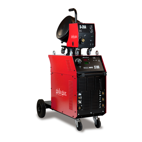
GALA MIG 5100
Ref. 421.00.000
GALA 4100 COMPLET
Ref. 422.00.000
Ref. 420.17.045 / Ed3
Advertisement
Table of Contents

Related Manuals for gala gar GALA MIG 410


Summary of Contents for gala gar GALA MIG 410
- Page 1 GALA INDUSTRIAL MANUAL TÉCNICO DE INSTRUCCIONES. FUENTES DE POTENCIA. EQUIPOS INDUSTRIALES DE SOLDADURA MIG/MAG DE REGULACIÓN ELECTRÓNICA. TECHNICAL INSTRUCTIONS MANUAL. POWER SOURCES. INDUSTRIAL MIG/MAG WELDING EQUIPMENT OF ELECTRONIC REGULATION. GALA MIG 4100 Ref. 420.00.000 GALA MIG 5100 Ref. 421.00.000 GALA 4100 COMPLET Ref.
-
Page 2: Table Of Contents
GALA GAR The decision to repair or replace parts or supply a new appliance will depend on the criterion of GALA GAR All replaced parts and products will be the property of GALA GAR In order for the guarantee to become effective the product and the purchase invoice must be handed over, duly completed and stamped by an authorized Technical Service. -
Page 3: Capitulo 1. Descripción General. Características Técnicas
GALA INDUSTRIAL. Manual de Instrucciones. CAPITULO 1. DESCRIPCIÓN GENERAL. CARACTERÍSTICAS TÉCNICAS. Estos equipos forman parte de un sistema modular (GALA INDUSTRIAL) que permite la soldadura eléctrica mediante el procedimiento semiautomático MIG-MAG de aceros al carbono, aceros débilmente aleados, aceros inoxidables y aluminio, que son los metales más utilizados en la industria moderna. El conjunto del sistema modular que configura la instalación, comprende los siguientes elementos: 1.1- Fuente de potencia. - Page 4 GALA INDUSTRIAL. Manual de Instrucciones. Fig. 1- Dimensiones generales de los equipos GALA INDUSTRIAL. Sistema modular. OPCIÓN (A) CON SOPORTE BOTELLAS. No permite refrigeración modular. D-12 A. Ref. 618.00.000. Dos ruletas . D-20 A. Ref. 621.00.000. Cuatro ruletas. GALA MIG 4100 Ref. 420.00.000. Mig/Mag GALA 4100 COMPLET.
- Page 5 GALA INDUSTRIAL. Manual de Instrucciones. 1.2. DEVANADORAS D-12 A ; D-20 A ; D-20 AR D-12 A: Devanadora abierta con cubre rollo. Motor de arrastre con dos ruletas engranadas φ40 mm. Control de velocidad de hilo y tensión de soldadura. Posibilidad de incorporar refrigeración. D-20 A: Devanadora abierta con cubre rollo.
-
Page 6: Capitulo 2. Transporte E Instalación
GALA INDUSTRIAL. Manual de Instrucciones. CAPITULO 2. TRANSPORTE E INSTALACIÓN Fig. 2 Sistema de elevación. En el transporte del equipo deben evitarse los golpes y los movimientos bruscos. La posición del transporte será la referida por las flechas indicativas del embalaje. Debe protegerse el embalaje de la caída de agua. - Page 7 GALA INDUSTRIAL. Manual de Instrucciones. CAMBIO DE TENSIÓN Todos equipos serie GALA Los equipos standard salen de fábrica con el INDUSTRIAL son bitensión (versión standard a selector de tensión a 400 V. Para cambiarlo a la 230/400V.), por ello, es preciso comprobar que la tensión de 230 coloque el tornillo T en la posición tensión seleccionada en el equipo coincide con el 2.
- Page 8 GALA INDUSTRIAL. Manual de Instrucciones. 2.3. INSTALACIÓN DEL SISTEMA MODULAR MIG REFRIGERADO. En la Fig.5 se describe el proceso de instalación del sistema modular MIG refrigerado. El sistema es equivalente al de la fig. 4. Incluyendo refrigeración. O/I- Tubos de agua fría y caliente (ROJO). M- Conexión del sistema de refrigeración Fig.
- Page 9 GALA INDUSTRIAL. Manual de Instrucciones. 2.4. INSTALACIÓN CON MODO DE TRABAJO DE ELECTRODO EN EQUIPOS MULTIPROCESO. Fig. 7. Instalación del equipo GALA INDUSTRIAL (MULTIPROCESO) en soldadura de ELECTRODO. ATENCION: EN ESTE MODO DE TRABAJO DEBE DESCONECTARSE LA DEVANADORA. G- PINZA DE SOLDADURA. (en este caso a positivo) J- MASA DE SOLDADURA.
-
Page 10: Capitulo 3. Puesta En Marcha. Funcionamiento Y Reglajes
GALA INDUSTRIAL. Manual de Instrucciones. CAPITULO 3. PUESTA EN MARCHA. FUNCIONAMIENTO Y REGLAJES. 3.1 PUESTA EN MARCHA OPERACIONES PREVIAS. En principio, la conexión del sistema debe realizarse tal como se indica en el capítulo anterior y antes de realizar una puesta en marcha definitiva del sistema, realice las siguientes operaciones (Obsérvense Fig. 5/6): 1º) Asegurarse que la tensión en la red es la misma que tiene preseleccionada la máquina (Fig. - Page 11 GALA INDUSTRIAL. Manual de Instrucciones. 3.2. FUENTE DE POTENCIA. MANDOS DE OPERACIÓN. En la Fig. 10 se dibujan los paneles de control de los equipos GALA INDUSTRIAL. Las operaciones realizadas por los mandos se describen seguidamente: Fig. 10. Paneles de control de los equipos GALA INDUSTRIAL. GALA MIG GALA COMPLET (MULTIPROCESO) N- INTERRUPTOR GENERAL.
- Page 12 GALA INDUSTRIAL. Manual de Instrucciones. 3.3. DEVANADORAS. MANDOS DE OPERACIÓN. Sobre la devanadora existirá no solamente el potenciómetro de regulación de velocidad de hilo sino que además existirá el potenciómetro de regulación continua de la tensión de soldadura. Para realizar una operación correcta lea el manual de instrucciones de las devanadoras. 3.4.
-
Page 13: Capitulo 4. Operaciones De Mantenimiento Recomendaciones
GALA INDUSTRIAL. Manual de Instrucciones. SOLDADURA DEL ALUMINIO. El gas a utilizar en este caso es Argón puro (sistema de soldadura MIG). Los caudales estarán comprendidos entre 8 y 18 l/min. Aconsejamos la utilización de un hilo de Aluminio de diámetro mínimo de 1 mm. El aluminio es un material blando que puede ocasionar problemas en el arrastre. -
Page 14: Capitulo 5. Anomalías. Causas Probables. Soluciones Posibles
GALA INDUSTRIAL. Manual de Instrucciones. CAPITULO 5. ANOMALÍAS. CAUSAS PROBABLES. SOLUCIONES POSIBLES. SÍNTOMA. ANOMALÍA CAUSA PROBABLE. SOLUCIÓN POSIBLE. La máquina carece de tensión en alguno o 1.Observar que la tensión en la entrada de la todos sus elementos vitales. máquina existe; de no ser así hay que proceder a PROBLEMA GENERAL. - Page 15 GALA INDUSTRIAL. Manual de Instrucciones. SÍNTOMA. ANOMALÍA CAUSA PROBABLE. SOLUCIÓN POSIBLE. EL INICIO DE LA Se esta realizando labores de punteado con Coloque la toma de masa en el valor de inductancia una toma de inductancia elevada. más bajo. SOLDADURA ES MUY Se esta realizando soldadura de aluminio Examine el proceso de arrastre.
-
Page 16: Capitulo 6. Medidas De Seguridad
GALA INDUSTRIAL. Manual de Instrucciones. CAPITULO 6. MEDIDAS DE SEGURIDAD. La utilización de estos equipos exige en su utilización y mantenimiento un grado máximo de responsabilidad. Lea atentamente este capitulo de seguridad, así como el resto del manual de instrucciones, de ello dependerá que el uso que haga del equipo sea el correcto. -
Page 17: Chapter 1. General Description Technical Characteristics
GALA INDUSTRIAL. Instructions Manual. CHAPTER 1. GENERAL DESCRIPTION. TECHNICAL CHARACTERISTICS. This equipment forms part of a modular system (INDUSTRIAL GALA) that permits electric welding of carbon steels, slightly alloyed steels, stainless steels and aluminium, which are the most commonly used metals in modern industry, by means of the MIG-MAG semiautomatic procedure. - Page 18 GALA INDUSTRIAL. Instructions Manual. Fig. 1 - General dimensions of the INDUSTRIAL GALA equipment Modular System. OPTION (A) WITH BOTTLE SUPPORT. Does not permit modular cooling. D-12 A. Ref. 618.00.000. Two rollers . D-20 A. Ref. 621.00.000. Four roller. GALA MIG 4100 Ref. 420.00.000. Mig/Mag GALA 4100 COMPLET.
- Page 19 GALA INDUSTRIAL. Instructions Manual. 1.2. WIRE-FEED UNITS D-12 A ; D-20 A ; D-20 AR D-12 A: D-12 A: Open wire-feed with roll-cover. Drive motor with two geared φ 40 mm rollers. Wire speed control and welding voltage Possibility of incorporating an cooling unit. D-20 A: Open wire-feed with roll-cover.
-
Page 20: Chapter 2. Transport And Installation
GALA INDUSTRIAL. Instructions Manual. CHAPTER 2. TRANSPORT AND INSTALLATION. Fig. 2 - Elevation system. Knocks and sudden movements must be avoided when transporting the equipment. The transport position will be shown by arrows on the packaging. In any case, the packaging must be protected from water. - Page 21 GALA INDUSTRIAL. Instructions Manual. VOLTAGE CHANGE All the equipment from the GALA INDUSTRIAL Standard equipment leaves the factory with the series have two voltages (standard version at voltage selected at 400 V. To change to 230 230/400 V). Therefore it is necessary to check that voltage place screw T in position 2.
- Page 22 GALA INDUSTRIAL. Instructions Manual. 2.3. INSTALLATION OF COOLED MIG MODULAR SYSTEM. Fig. 5 describes the cooled MIG modular system installation process. The system is the equivalent to that shown in fig. 4. Including cooling. O/I- Hot and cold water pipes (RED). M- Connection of cooling system.
- Page 23 GALA INDUSTRIAL. Instructions Manual. 2.4. INSTALLATION WITH ELECTRODE WORKING MODE IN MULTIPROCESSING EQUIPMENT. Fig. 7. Installation of GALA INDUSTRIAL equipment (MULTIPROCESSING) in ELECTRODE welding. WARNING: THE WIRE-FEED UNIT MUST BE DISCONNECTED IN THIS WORKING MODE. G- ELECTRODE-HOLDER CLAMP. (in this case to positive) K- EARTH CLAMP.
-
Page 24: Chapter 3. Start-Up. Adjustment And Operation Controls
GALA INDUSTRIAL. Instructions Manual. CHAPTER 3. START-UP. ADJUSTMENT AND OPERATION CONTROLS. 3.1 START-UP. PRELIMINARY OPERATIONS. In principle, the system must be connected as indicated in the previous chapter and before starting the system up definitely, the following steps must be taken (See Fig. 5/6): 1)- Make sure the mains voltage is the same as that pre-selected in the machine (Fig. - Page 25 GALA INDUSTRIAL. Instructions Manual. 3.2. POWER SOURCE. OPERATION CONTROLS. The INDUSTRIAL GALA equipment control panels are given in figure 10. The operations carried out by the controls are described below: Fig. 10. Control panels of the INDUSTRIAL GALA equipment. GALA MIG GALA COMPLET (MULTIPROCESSING) N- GENERAL ON/OFF SWITCH.
- Page 26 GALA INDUSTRIAL. Instructions Manual. 3.3. WIRE-FEED UNITS. OPERATION CONTROLS. Apart from the wire speed adjustment potentiometer on the wire-feed unit there will also be a continuous welding voltage adjustment potentiometer. In order to carry out a correct operation, please read the wire-feed units instructions manual. 3.4.
-
Page 27: Chapter 4. Maintenance Operations. Recommendations
GALA INDUSTRIAL. Instructions Manual. ALUMINIUM WELDING. The gas to be used in this case is pure Argon (MIG welding system). The flows will be between 8 and 18 l/min. We advise using an aluminium wire with a minimum diameter of 1 mm. Aluminium is a soft material, which can cause problems in driving. -
Page 28: Chapter 5. Anomalies. Probable Causes. Possible Solutions
GALA INDUSTRIAL. Instructions Manual. CHAPTER 5. ANOMALIES. PROBABLE CAUSES. POSSIBLE SOLUTIONS. SYMPTOM. ANOMALY. PROBABLE CAUSE. POSSIBLE SOLUTION. The machine has no voltage in one or all its 1. Make sure there is voltage at the entry to the vital elements. machine, if not the tapping must be changed. - Page 29 GALA INDUSTRIAL. Instructions Manual. SYMPTOM. ANOMALY. PROBABLE CAUSE. POSSIBLE SOLUTION. THE WELDING START IS Spotting jobs are being carried out with high Place the earth tap at the lowest inductance value inductance intake. VERY AGGRESSIVE. Aluminium is being welded with a drawing Examine the drawing process.
-
Page 30: Chapter 6. Safety Measures
GALA INDUSTRIAL. Instructions Manual. CHAPTER 6. SAFETY MEASURES. The use of this equipment requires a maximum amount of responsibility with respect to their use and maintenance. Read this safety chapter carefully as well as the rest of the instructions manual. The correct use of the equipment will depend on this. -
Page 31: Anexos
GALA INDUSTRIAL. ANEXOS. PLANOS ELÉCTRICOS Y DESPIECES. • DECLARACIÓN DE CONFORMIDAD PARA EL MARCADO CE. • ESQUEMAS ELÉCTRICOS. • PLANOS DE DESPIECE Y LISTA DE REFERENCIAS. GB APPENDICES. ELECTRICAL DRAWINGS AND REFERENCE PART LISTS. • DECLARATION OF CONFORMITY & EC MARKING •... - Page 32 TRAFO PRAL. TRAFO PRAL. TRAFO PRAL. MIG 4100 MIG 4100 MIG 5100 COMPLET MARCA REF.42012015 REF.42112015 REF.42212015 DESCRIPCION 42012115 42112115 42212115 BOBINA SALIDAS CORTAS MIG (230/400V) 42012215 42112215 42212215 BOBINA CENTRAL MIG (230/400V) 42012315 42112315 42212315 BOBINA SALIDAS LARGAS MIG (230/400V) 49800001 49800001 49800001...
- Page 33 FABRICACIÓN Y VENTA DE APARATOS DE SOLDADURA AUTOGENA, ELECTRICA Y CONSTRUCCIONES ELECTROMECANICAS MANUFACTURE AND SALE OF AUTOGENOUS, AND ELECTRIC WELDING APPLIANCES, AND ELECTROMECHANICAL CONSTRUCTIONS. CENTRAL: Jaime Ferrán, 19, nave 30 Apartado de Correos 5058 50080 ZARAGOZA Teléfono 976 47 34 10 Telefax 976 47 24 50 E-mail: comercial@galagar.com Internet: http://www.galagar.com...
Need help?
Do you have a question about the GALA MIG 410 and is the answer not in the manual?
Questions and answers