Table of Contents
Advertisement
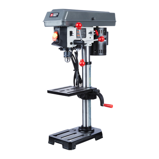
10 IN. (254 MM) DRILL PRESS
PERCEUSE À COLONNE DE 254 MM
(10 PO)
254 MM (10 PULGADAS)
PERFORADORA DE COLUMNA
Instruction Manual
Manuel d'instructions
Manual de instrucciones
www.portercable.com
INSTRUCTIVO DE OPERACIÓN,
CENTROS DE SERVICIO Y PÓLIZA
DE GARANTÍA.
CATALOG NUMBER
ADVERTENCIA: LÉASE ESTE
PCXB620DP
INSTRUCTIVO ANTES DE USAR EL
PRODUCTO.
1
Advertisement
Table of Contents

Related Manuals for Porter-Cable PCXB620DP


Summary of Contents for Porter-Cable PCXB620DP
-
Page 1: Instruction Manual
PERCEUSE À COLONNE DE 254 MM (10 PO) 254 MM (10 PULGADAS) PERFORADORA DE COLUMNA Instruction Manual Manuel d’instructions Manual de instrucciones www.portercable.com INSTRUCTIVO DE OPERACIÓN, CENTROS DE SERVICIO Y PÓLIZA DE GARANTÍA. CATALOG NUMBER ADVERTENCIA: LÉASE ESTE PCXB620DP INSTRUCTIVO ANTES DE USAR EL PRODUCTO. -
Page 2: Table Of Contents
TABLE OF CONTENTS SECTION PAGE PRODUCT SPECIFICATIONS ................... CALIFORNIA PROPOSITION 65................SAFETY GUIDELINES - DEFINITIONS ..............POWER TOOL SAFETY ..................... ADDITIONAL SAFETY RULES FOR DRILL PRESSES..........ELECTRICAL REQUIREMENTS AND SAFETY ............TOOLS NEEDED FOR ASSEMBLY ................CARTON CONTENTS ....................KNOW YOUR DRILL PRESS ............... GLOSSARY OF TERMS.................... -
Page 3: California Proposition 65
CALIFORNIA PROPOSITION 65 WARNING Some dust created by power sanding, sawing, grinding, drilling and other construction activities contains chemicals known to the state of California to cause cancer, birth defects or other reproductive harm. Some examples of these chemicals are: ●... -
Page 4: Power Tool Safety
POWER TOOL SAFETY GENERAL SAFETY INSTRUCTIONS 9. USE THE RIGHT TOOL. Do not force the BEFORE USING THIS POWER TOOL tool or an attachment to do a job for which Safety is a combination of common sense, it was not designed. staying alert and knowing how to use your power tool. - Page 5 16. REDUCE THE RISK OF 21. DO NOT OVERREACH. Keep proper UNINTENTIONAL STARTING. Make footing and balance at all times. sure switch is in the OFF position before plugging the tool in. 22. MAINTAIN TOOLS WITH CARE. Keep tools sharp and clean for best and safest 17.
-
Page 6: Additional Safety Rules For Drill Presses
ADDITIONAL SAFETY RULES FOR DRILL PRESS Following good safety practices when using 10. SECURE THE WORK. Use clamps or a drill presses is a must. Make a habit of vise to hold the work. It’s safer than using including safety in all your activities. your hand and it frees both hands to operate tool. - Page 7 22. DO NOT use bits with screw tips. These 27. DO NOT FORCE DRILLING. The tool will bits will pull the workpiece up from the do the job better and safer at the rate for table and start to spin, causing a serious which it is was intended.
-
Page 8: Electrical Requirements And Safety
ELECTRICAL REQUIREMENTS AND SAFETY POWER SUPPLY AND MOTOR Use a separate electrical circuit for your tool. SPECIFICATIONS This circuit must not be less than #18 wire and should be protected with a 3.2 Amp time WARNING lag fuse. Before connecting the motor to the To avoid electrical hazards, fire hazards, power line, make sure the switch is in the off or damage to the tool, use proper circuit... - Page 9 WARNING This tool is for indoor use only. Do not expose to rain or use in damp locations. This tool is intended for use on a circuit that has a receptacle like the one illustrated in Fig. 1. Fig. 1 shows a three-pronged electrical plug and receptacle that has a grounding conductor.
-
Page 10: Tools Needed For Assembly
CARTON CONTENTS TOOLS NEEDED FOR ASSEMBLY Supplied Not Supplied UNPACKING AND CHECKING CONTENTS Carefully unpack the drill press and all its parts, and compare against the list below and the illustration on the next page. Place the 3 mm hex key Slotted screwdriver drill press on a secure surface and examine it carefully. - Page 11 UNPACKING YOUR DRILL PRESS...
-
Page 12: Know Your Drill Press
KNOW YOUR DRILL PRESS Depth scale Depth stop pointer ON/OFF LED nuts Pulley cover light switch Motor pulley Quill return coil / spring Spindle pulley Front Rear LED light Feed Rack ring handles Bevel lock Table lock bolt handle Pulley cover Chuck key holder Belt tension Base... -
Page 13: Glossary Of Terms
GLOSSARY OF TERMS BASE – Supports drill press. For additional DRILLING SPEED – Changed by placing stability, holes are provided in the base to bolt the belt in any of the steps (grooves) in the drill press to the floor. (See “ADDITIONAL pulleys. -
Page 14: Assembly And Adjustments
ASSEMBLY AND ADJUSTMENTS Estimated Assembly Time: 25 - 35 Minutes. Fig. B WARNING ● For your safety, never connect plug to power source receptacle until all assembly and adjustment steps are all complete, and you have read and understood the safety instructions. ●... - Page 15 1. Carefully lift the head (1) and slide it onto 6. Install the rack ring (6) onto the column, the column (2). Make sure the head (1) so the top lip of the rack sits into the rack slides down over the column as far as ring (6).
- Page 16 1. Bag “E” - Clean out the tapered hole in 2. Place a ball joint separator (not shown) the chuck (1) with a clean cloth and a above the chuck and tap it lightly with a non-alcohol based cleaner. Wipe clean all hammer or rubber mallet to cause the oil reside and any dirt or grime thoroughly.
- Page 17 Fig. L Fig. M ADJUSTMENTS INSTRUCTIONS NOTE: All the adjustments for the operation of the drill press have been completed at the factory. Due to normal wear and use, some occasional readjustments may be necessary. WARNING SPINDLE / QUILL (FIG. N) To avoid injury from an accidental start, Rotate the feed handles counterclockwise ALWAYS make sure the switch is in the...
- Page 18 QUILL RETURN SPRING (FIG. O) BELT TENSION (FIG. P) The quill return spring may need adjustment WARNING if the quill return speed is too fast or too slow. To avoid injury from an accidental start, This spring is located on the left side of the ALWAYS make sure the switch is in drill head.
-
Page 19: Operation
OPERATION BASIC DRILL PRESS OPERATION ON/OFF SWITCH (FIG. S) The ON/OFF switch has a removable, safety WARNING key. With the safety key removed from the To avoid possible injury, keep guard switch, unauthorized and hazardous use by closed and in place while tool is in children and others is minimized. - Page 20 INSTALLING DRILL BIT IN CHUCK (FIG. U) Depth scale method (Fig. W) 1. With the switch “OFF” and the safety key NOTE: With the chuck in the upper position, removed, open the chuck jaws (1) using the tip of the drill bit must be just slightly the chuck key (2).
- Page 21 BASIC OPERATION INSTRUCTIONS WARNING To get the best results and minimize the When using a drill press vise, it MUST likelihood of personal injury, follow these be clamped or bolted to the table to instructions for operating your drill press. avoid injury from a spinning workpiece, or damaged vise or bit parts.
- Page 22 FEEDING 1. Pull down the feed handles with only enough effort to allow the drill bit to cut. 2. Feeding too slowly might cause the drill bit to burn. Feeding too rapidly might cause the belt or drill to slip, tear the workpiece loose or break the drill bit.
-
Page 23: Maintenance
Do not use any accessory unless you Since accessories, other than those offered have completely read the Instruction by Porter-Cable, have not been tested with Manual for that accessory. this product, use of such accessories with this tool could be hazardous. To reduce the risk of injury, only Porter-Cable recommended accessories should be used with this product. -
Page 24: Troubleshooting Guide
Use only identical replacement parts. For a parts list or to order parts, visit our service website at www.portercable.com. You can also order parts from your nearest Porter-Cable Factory Service Center or Porter-Cable Authorized Warranty Service Center. Or, you can call our Customer Care Center at (888) 609-9779. - Page 25 See Section trying to “ASSEMBLY INSTALLING THE install. CHUCK”. For assistance with your product, visit our website at www.portercable.com for a list of service centers, or call the Porter-Cable Customer Care Center at (888) 609-9779.
-
Page 26: Parts List
PARTS LIST 10 IN. (254 MM) DRILL PRESS PARTS LIST I.D. No. Description Size Q'ty I.D. No. Description Size Q'ty X758 PULLEY SET NUT 1"-20 X773 QUILL SET SCREW M8*1.25-14 X759 BATTERY X774 HEX. NUT M8*1.25 T=6.5 X75A SWITCH KEY X778 SPRING PIN X75C POWER CORD... - Page 27 10 IN. (254 MM) DRILL PRESS SCHEMATIC X758 X77K X77W X7BA X7BB X77N X77A X77M X7B8 X77L X77P X7B9 X77J X77L X77B X77H X77D X77C X77G X77E X77F X77X X779 X76L X778 X774 X77N X75C X773 X7AZ X76K X76S X772 X76M X76J X77X...
-
Page 28: Warranty
90 DAYS MONEY BACK GUARANTEE: If you are not completely satisfied with the performance of your PORTER-CABLE Power Tool for any reason, you can return it within 90 days from the date of purchase with a receipt for a full refund – no questions asked.
Need help?
Do you have a question about the PCXB620DP and is the answer not in the manual?
Questions and answers
I need a return spring, porter cable pcxb620dp, mine broke off HELP