Table of Contents
Advertisement
Quick Links
Advertisement
Table of Contents
Troubleshooting

Subscribe to Our Youtube Channel
Related Manuals for Sena Rhio10


Summary of Contents for Sena Rhio10
- Page 1 Rhio10 Remote I/O Manager User Manual Version 1.4.3 2007-05-07...
- Page 2 Firmware version 1.4.x Printed in Korea Copyright Copyright 2002~2007, Sena Technologies, Inc. All rights reserved. Sena Technologies reserves the right to make changes and improvements to its product without providing notice. Trademark HelloDevice™ is a trademark of Sena Technologies, Inc.
-
Page 3: Revision History
Name Description V1.0.0 2005-05-21 D.H. Shin Initial Release V1.0.1 2005-08-08 D.H. Shin “ Table 2-2. Terminal Block Assignment of the Rhio10 “is added. V1.0.2 2005-11-02 D.H. Shin Typo errors corrected. V1.0.3 2005-11-08 JS. Kim Operating and storage temperature is updated. -
Page 4: Table Of Contents
Table of Contents 1. Introduction ..........7 1.1 Overview ...........................7 1.2 Package Check List ........................7 1.3 Product Specification .........................8 2. Getting Started ..........10 2.1 Panel Layout ........................... 10 2.2 Connecting the Hardware ......................12 2.2.1 Setting up DIN Rail mount kit..................12 2.2.2 Connecting the Power ....................13 2.2.3 Connecting to the Network ....................14 2.3 Rhio Manager Installation......................14... - Page 5 4.3.1 Setting Enable/Disable ....................35 4.3.2 Setting run condition......................36 4.3.3 Delay & Pulse Operation ....................37 4.3.4 Setting Power-out Post Recovery ..................37 4.4 ADC Input Port Setting......................37 4.4.1 Setting Reference ......................38 4.4.2 Setting ADC Input Port ....................38 4.5 I/O Port Connection .........................39 4.5.1 Digital Output Port......................39 4.5.2 Digital Input Port......................39 4.5.3 ADC Input Port......................40...
- Page 6 B.2 Command Usage ........................70 B.2.1 'set' Command......................71 B.2.2 'get' Command......................72 B.2.3 'help' Command......................74 B.2.4 'save' Command......................75 B.2.5 'exit' Command......................75 B.2.6 'reboot' Command......................75 B.3 System Configuration using Console command................ 75 B.3.1 Network Configuration....................75 B.3.2 Host Mode Configuration....................76 B.3.3 System Administration....................78 Appendix C.
-
Page 7: Introduction
Rhio10 supports 10 Digital Relay Output ports and has basic logic function capability such as AND, OR, NOT and Delay/Pulse along with the status of the input ports. Rhio10 supports 12 optically isolated digital inputs for monitoring of the digital sensors. Rhio10’ s Analog ports support both level mode for data acquisition and switch mode for threshold detection. -
Page 8: Product Specification
1.3 Product Specification 10 Base-T Ethernet with RJ45 Ethernet connector Network Interface Supports static and dynamic IP address -Number of channels: 12 -Input type: Voltage -Input circuitry: Optically isolated photo-coupler -Input range: 0V ∼ ±24V Digital Input OFF 0V ∼ ±1.2V, ON ±3.3V ∼ ±24V -Sampling rate: 20ms -Isolation voltage: 5KV - Number of channels: 10... - Page 9 137 x 111 x 58 (mm), 5.4 x 4.4 x 2.3 (in.) Physical properties Weight: 730g Certification FCC (A), CE, MIC Warranty 5-year limited warranty...
-
Page 10: Getting Started
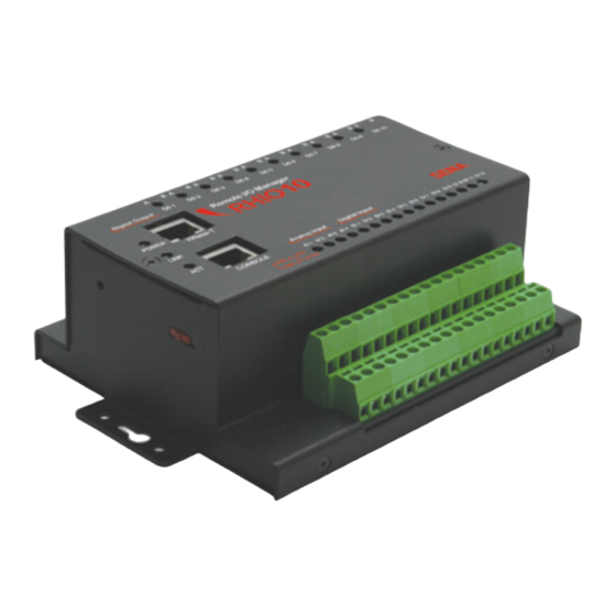
12 lamps for digital input status, and lamps for 4 analog port status. There is a DIP switch on the side of the Rhio10 for data/console switching and hole for factory reset operation. Table 2-1 shows the description of the indicator lamps of the Rhio10. - Page 11 Figure 2-1. The panel layout of theRhio10 Table 2-2. Terminal Block Assignment of the Rhio10 DI10 DI11 DI12 • Power Input ( PWR_A , PWR_B ): (1,2) •Analog reference voltage ( Ref ) : (3) -It is analog reference voltage input block. Rhio represents voltage from 0 V to a reference Input voltage in 1,024 steps.
-
Page 12: Connecting The Hardware
2.2 Connecting the Hardware 2.2.1 Setting up DIN Rail mount kit Users may use DIN rail mounting kit included in the package to install the Rhio10 on to the DIN rail. Figure 2-2. Dimension of DIN Rail mount kit and applicable DIN Rails... -
Page 13: Connecting The Power
Figure 2-4. Setting up the Rhio10 to DIN Rail 2.2.2 Connecting the Power Supply the proper power according to the power specification of the Rhio10, i.e. 9V~48VDC, MAX. 5W. If the power is properly applied, [Power] indicator will maintain RED. Be sure not to use the cable longer than 3m for normal operation. -
Page 14: Connecting To The Network
2.2.3 Connecting to the Network Connect the one end of the Ethernet cable to the Rhio10 10Base -T port and the other to the Ethernet network. If the cable is properly hooked up, the Rhio10 will have a valid connection to... -
Page 15: Basic Configuration Using Rhio Manager
Figure 2.7 Rhio Manager screen layout 2.3.2 Basic configuration using Rhio Manager Select Interface It specifies the communication method between Rhio10 and Rhi0 Manager. Be sure to set it up as “ Network”mode. Quick Connect Users may connect to the Rhio10 from using Rhio Manager by specifying the destination IP address. - Page 16 Users may probe the Rhio10 on the network. If users perform [Probe] command, then the Rhio10 detected will be shown on the Probe screen. If users select the one in the Probe screen, then they are asked to enter ID and Password. Users are able to configure the Rhio10 ’ s parameters within the Get/Set screen.
-
Page 17: System Configuration And Administration
3. System Configuration and Administration 3.1 Network Configuration A valid IP address of the Rhio10 needs to be assigned before it starts to work in the user's network environment. A network system administrator may provide the user with this IP address setting information for the network. - Page 18 The factory default configuration of IP mode is DHCP mode. In order to detect the Rhio10 for the first time, users have to perform [Probe] function by using Rhio Manager. If there is a DHCP server on the users’ environment, then the IP address assigned by the DHCP server is displayed.
-
Page 19: Static Ip
A subnet represents all the network hosts at one geographic location, in one building, or on the same local area network. When there is any outgoing packet over the network, the Rhio10 will check whether the desired TCP/IP host specified in the packet is on the local network segment... -
Page 20: Dhcp
If the operating time reaches the lease time, the Rhio10 will request the DHCP server for renewal of its lease time. If the DHCP server approves extending the lease, the Rhio10 can continue to work with the current IP address. -
Page 21: Pppoe
- Hosts on the a specific subnet can access the Rhio10 - Any host can access the Rhio10 The user may allow a host or a group of hosts to access the Rhio10. Then the user must enter the IP address and subnet to be allowed for accessing. -
Page 22: Host Mode Configuration
255.255.255.255 for the subnet. To allow any hosts to the Rhio10, give 0.0.0.0 for both of the IP address and subnet. Please refer to Table 3-2 for more details. Table 3-2 Input examples of allowed remote hosts Input format... - Page 23 If the connection is not established, it will accept all incoming connection and connect to the remote host if there are any I/O status data. Otherwise, it will send data back and forth. In summary, the Rhio10 will work as if it is virtually connected to the remote host.
- Page 24 [Established]. This state is not valid in TCP client mode. Sync-Sent If the Rhio10 sends a connection request to a remote host, the state is changed from [Closed] to [Sync-Sent]. This state is maintained until the remote host accepts the connection request. This state is valid only in TCP client mode.
-
Page 25: Tcp Server Mode Operations
3.2.1 TCP Server Mode Operations The Rhio10 works as a TCP server, and the default TCP state is [Listen] in this mode. The Rhio10 supports only one TCP socket connection. If a connection is currently established, the additional connection requests will be rejected. The remote host will be a socket program acting as a TCP client running on user ’PC. - Page 26 Inactivity timeout is set to maintain the TCP connection state as Closed or Listen in TCP host mode unless there is any I/O data transfer between the I/O device and the Rhio10. If there is no incoming or outgoing I/O data during the specified inactivity timeout interval, the existing TCP connection will be closed automatically.
-
Page 27: Tcp Client Mode Operation
[Closed] --> [Sync-Sent] --> [Established] --> [Data] --> [Closed] At start-up, an initial TCP state is [Closed]. If there is any changed in I/O state, the Rhio10 will try to connect to a user-defined remote host. Then, the state will be changed to [Sync-Sent], which means the connection request is being sent. - Page 28 Cyclic Connection It Cyclic Connection function is enabled, the Rhio10 will make an attempt to connect to the user- defined remote host at certain interval even if there’ s no change in the I/O status data. If the remote host prepares I/O control/monitor command, it will be transferred to the Rhio10 after the connection is established.
-
Page 29: Tcp Server/Client Mode Operation
RHIO10 is always connected to the specified remote host. 2) Operations The only difference from TCP server mode is that the RHIO10 will try to connect and send I/O state data to the remote host even if the TCP session is not established. The difference from TCP client mode is that it will accept incoming connection request from remote host if the session is not established. -
Page 30: System Administration
Users may change the ID/Password and Device Name within the Rhio Manager admin section. Users have to click the [Clear] button after they change the ID/Password to clear the ID/Password configuration in the Rhio Manager as well. Device Name can be set up to discriminate the Rhio10 devices on the network. -
Page 31: Restoring Factory Default
Users may restore the Rhio10 parameters into factory default value by pressing factory reset switch on the hole of Rhio10 side panel. They will have to put the sharp pin into the hole and press it for around 1 sec to reset the Rhio10. Rhio10 will be rebooted after the operation. -
Page 32: I/O Setting And Application
You can monitor, control and set I/O states by pressing the [I/O PORT CONTROL] button. Once [I/O PORT CONTROL] is invoked, Rhio Manager begins to monitor the I/O state by connecting to a local port of Rhio10 via a TCP socket. To allow this process, the Rhio10 should be set to TCP server mode. -
Page 33: Specifying Monitoring Interval
4.1.2 Specifying monitoring interval You can continue to monitor the I/O state of Rhio10 at a specified time interval by setting [Setting Monitor Interval]. The valid value for monitoring intervals is any number between 2 and 10 seconds. In the specified time interval, Rhio Manager sends a state request command and receives a response from Rhio10 and displays it on the screen. -
Page 34: Digital Input Setting
4.2 Digital Input Setting Rhio10 has 12 digital input ports. You can enable/disable each of these digital input ports with Rhio Manager or by issuing the commands specified in "Ch. 5 I/O Port Related Protocols". When setting the digital input with Rhio Manager, place your mouse cursor over the Digital Input LED on the I/O Port Control screen and right -click it to display the Setting window. -
Page 35: Digital Output Port Setting
4.3 Digital Output Port Setting Rhio10 has 10 digital output ports. You can set each of these digital output ports with Rhio Manager or by issuing the commands specified in "Ch. 5 I/O Port Related Protocols". Place your mouse cursor over the Digital Output Port LED on the I/O Port Control screen and right-click it to display the Setting Output Port window. -
Page 36: Setting Run Condition
4.3.2 Setting run condition When the [Macro] check box is selected, you can enter a conditional expression and then use it to control operation of an output port. Enter the desired conditional expression in the [Macro] box. Specify an operation condition for each output port. An output port that has not been set is regarded as a port available for direct control. -
Page 37: Delay & Pulse Operation
If it is disabled, the output port state becomes OFF when power goes out and back on. 4.4 ADC Input Port Setting Rhio10 has 4 ADC input ports. You can set an ADC input port with Rhio Manager or by issuing commands via an I/O port protocol (refer to "Ch. 5 I/O Port Related Protocols” ). -
Page 38: Setting Reference
Figure 4-5 Setting ADC Input Port 4.4.1 Setting Reference Specify a reference voltage for analog input data. Rhio represents voltage from 0 V to a reference voltage in 1,024 steps. A reference voltage may not exceed 5 V. Specify a reference voltage in the Reference list box. -
Page 39: I/O Port Connection
This section describes how to make a required connection with the digital output, digital input and ADC input port of Rhio10 for the users’devices. The length of cables used for I/O port connection should be less than 3 meters to ensure normal operation. -
Page 40: Adc Input Port
Figure 4-7 Connection of Digital Input Port 4.5.3 ADC Input Port An ADC input port is a non-insulated input port. If possible, a circuit should be made using AVCC (+5V) voltage supplied from internal circuits. When operating in Switch mode, a threshold voltage should be specified. - Page 41 2) When using an Analog Input Potentiometer An analog input operates in reference to input voltage and has an impedance of 100㏀. When using a Potentiometer as shown in Figure 4-9, an impedance in the range of 1㏀ - 5㏀ is ideal. When using an external signal source, lower impedance ensures stable operation against various noises.
-
Page 42: Software Development & Application
5. Software Development & Application You can use the Rhio library to develop application software that is used to communicate with Rhio10. The Rhio Library Files RHIO_Proc.dll, RHIO_Process.h You must link these two files in order to develop software using the Rhio library. - Page 43 2) Structure (See Appendix D.2) Structure Description SADCData ON/OFF state of each port SOnOffStateData ON/OFF state of all ports SSetOutput Output port configuration information SSetADC ADC configuration information SSetInput Input port configuration information SRHIOSetting All ports configuration information 3) Function (See Appendix D.3) Function Description A function that creates Process Class that...
- Page 44 Send a command that enables/disables all RHIO_SndCmd_SetPortEnable ports. Send a command that checks enable/disable RHIO_SndCmd_GetPortEnable state of all ports. Send command that enables/disables RHIO_SndCmd_SetPwrStopEnable power-out recovery for all ports. Send a command that checks enable/disable RHIO_SndCmd_GetPwrStopEnable state of power-out recovery for all input ports. RHIO_SndCmd_SetFactoryReset Send Rhio Factory Reset command.
-
Page 45: Creating And Demonstrating A Sample Program With Rhio Library
5.2 Creating and demonstrating a sample program with Rhio library The sample program (RHIO_TEST) is a dialog box based application that has been created with Microsoft Visual Studio .NET linked to Rhio library (RHIO_Proc.dll, RHIO_Process.h). 5.2.1 Program UI Configuration and their related classes Figure 5-1 Main Window of a Sample Program Class Related Files... -
Page 46: Processing
Figure 5-2 Setting Window of a Sample Program Class Related Files CSettingDlg SettingDlg.h SettingDlg.cpp 5.2.2 Processing 5.2.2.1 Initializing Main window 1) Link the library and get the address of a required library function. CWEB_IO_TESTDlg::RHIODllLoad() 2) Initialize dialog items in Main window. CWEB_IO_TESTDlg::InitOutPutButton();... - Page 47 CWEB_IO_TESTDlg::InitSample(CPoint pntStart, int iWidth, int iHeight, int iTerm) CWEB_IO_TESTDlg::InitSelComm(); 3) Create Process Class. m_rhCreate(CWnd *pParentWnd) 5.2.2.2 Event Handling procedure When an event occurs in the main window of the program: ① The Connect button is clicked on. CWEB_IO_TESTDlg::OnBnClickedButtonConnect() TCP Connection m_rhSockConnect (BYTE bAddr1, BYTE bAddr2, BYTE bAddr3, BYTE bAddr4, int iPort) ...
- Page 48 ⑥ The Monitor Power Stop button is clicked on. CSettingDlg::OnBnClickedButtonMonitorPwrStop() ⑦ The Set Power Stop button is clicked on. CSettingDlg::OnBnClickedButtonSetPwrStop() ⑧ The Monitor Enable State of the Port button is clicked on. CSettingDlg::OnBnClickedButtonMonitorEnable() ⑨ The Enable Port button is clicked on. CSettingDlg::OnBnClickedButtonSetEnable() ⑩...
-
Page 49: Rhio Communication Protocol
5.3 Rhio Communication Protocol In this chapter, it covers how to send/receive the command/reply to/from Rhio device by using the Rhio communication protocol. 5.3.1 Overview You can use the Rhio communication protocol to set, control and monitor RHIO. 5.3.1.1 Command Block START LENGTH FUNCTION... - Page 50 - LRC (BCC) Checks for any Errors in the command block. Bytewise XORed value from START FLAG field to DATA field (refer to example below) - END FLAG CR+LF ( 0x0D+0x0A ) -. The data of LENGTH and LRC is expressed as follows. Each 4-bit nibble (upper 4-bit nibble and lower 4-bit nibble) is expressed as 1 Byte data.
-
Page 51: On/Off Control
- NAK Response START LENGTH FUNCTION DATA FLAG (BCC) FLAG Byte Size Start of the The length from Response from CR (0x0D) Command FUNCTION field “00” Data START LF (0x0A) Block, 0x3A to DATA field 0x30,0x30 “NAK” FLAG field to ( “:”... - Page 52 Data MASK Data Data Separator ON/OFF Data Data Order 1 - 10 12-21 Port No. 1 - 10 1-10 0x2C ( “,”) Control: 0x31 ON: 0x31 Data Content separates MASK Non-control: 0x30 OFF: 0x30 from ON/OFF. MASK and ON/OFF Data correspond to one port per byte for each port in sequence. Port location by Data Order Data Order...
- Page 53 0x30: OFF, “0000” -” 1023” : 8-12 0x31: ON (Switch Input), Level 0x39: Level Mode Field Separator 0x2C ( “ ,”) 0x30: OFF, “0000” -” 1023” : 14-18 0x31: ON (Switch Input), Level 0x39: Level Mode Field Separator 0x2C ( “ ,”) 0x30: OFF, “0000”...
-
Page 54: Input/Output State
Run Modes. Set/Run Rhio10 returns a state response once after set command is received. It does not return any state response until it receives run command even if it is switched to Setting mode. When setting output port, ADC input port, Port Enable, Port Power-out Recovery or serial number, send set command first to switch it to Setting mode. -
Page 55: Output Port Setting
5.3.4.2 Response for Set/Run command Same as "5.3.2.2 Response for ON/OFF control". In Setting mode, Rhio10 returns a response once and it does not respond until run command is received. The control state field of the state response, Rhio10 returns 0x31 in Setting mode and 0x30 in Run mode. - Page 56 A conditional expression only takes the form of a single expression with AND, OR, NOT. Eg. AND operation of Input #1 and Input #2 : I1 & I2 OR operation of Output #3 and Input #1 : O3 | I1 AND operation of the inversed Input #10 and Output #10 : !I10 &...
- Page 57 OFF after 5,000 sec delay “00000” “50000” Repeat 100 ms ON and 100 ms OFF. “00001” “00001” Repeat 2 sec ON and 2 sec OFF. “00020” “00020” Repeat 5,000 sec ON and 5,000 sec “50000” “50000” OFF. Repeat 1 sec ON and 3 sec OFF. “00010”...
-
Page 58: Adc Input Port Setting
5.3.5.4 Response for Check Output Port Setting command Same as "5.3.5.2 Response for Set Output Port command". 5.3.6 ADC Input Port Setting 5.3.6.1 Set ADC Input Port Command Command Data Remark Byte Size Set the threshold “ 08” level value for an Set it to a 10-bit ADC ( 0x30, 0x38 ) input ADC port. -
Page 59: Port Enable Setting
Setting Flag 0x30: Set OK 0x31: Not in Setting mode (in Run mode) 0x39: Set NG 5.3.6.3 Check ADC Input Port Setting Command Command Data Remark Byte Size “10” Check the ( 0x31, 0x30 ) 0x30: Fixed to a dummy threshold level Check the ADC value... - Page 60 Field Separator 0x2C ( “ ,”) 0x30: AVcc ( Vcc 5V ) -> default ADC Reference 0x31: Internal ( 2.56V ) Setting 0x32: External ( 2-4.5V ) Field Separator 0x2C ( “ ,”) 8-11 I1-I4 0x31: Enable, 0x32: Disable Field Separator 0x2C ( “ ,”) 13-16 I5-I8 0x31: Enable, 0x32: Disable...
- Page 61 0x30: Avcc ( Vcc 5V ) -> default 0x31: Internal ( 2.56V ) ADC Port 0x32: External ( 2V-4.5V ) Field Separator 0x2C ( “ ,”) 0x30: Avcc ( Vcc 5V ) -> default ADC Reference 0x31: Internal ( 2.56V ) Setting 0x32: External ( 2V-4.5V ) 9-12...
-
Page 62: Port Power-Out Post Recovery Setting
5.3.8 Port Power-out Post Recovery Setting 5.3.8.1 Set Port Power-out Post Recovery command Command Data Remark Byte Size “ 14” Set Power-out ( 0x31, 0x34 ) The Port Power-out Post Post Recovery to Set Power-out Post Recovery setting data Enable/Disable Recovery to for an output port Enable/Disable. - Page 63 O1-O4 0x31: Enable, 0x32: Disable Field Separator 0x2C ( “,” ) Output State 7-10 O5-O8 0x31: Enable, 0x32: Disable Field Separator 0x2C ( “,” ) 12, 13 O9, O10 0x31: Enable, 0x32: Disable 5.3.8.3 Check Port Power-out Post Recovery Setting command Command Data Remark...
-
Page 64: Appendix A. Connection
Brown A.2 Console Port Pin Outs The pin assignment of the RHIO10 RJ45 connector is summarized in Table A-2. Each pin has a function according to the serial communication type configuration. Note : When connecting console port to host, user should use the other end of CAT5 cable using RJ45 to DB9 Female connector(included package). -
Page 65: Ethernet Wiring Diagram
Description Table A-2. Pin assignment of the RJ45 connector A.3 Ethernet Wiring Diagram Figure A-3. Ethernet direct connection using crossover ethernet cable... -
Page 66: Serial Console Wiring Diagram
Figure A-4. Ethernet connection using straight through ethernet cable A.4 Serial Console Wiring Diagram Figure A-5. RS232 wiring diagram... -
Page 67: Appendix B. Accessing Console Port And Command Usage
Accessing Console Port and Command Usage B.1 Accessing Console Port There are two ways to access console port of the RHIO10 depending on whether the user is located at a local site or a remote site. - Serial console: Local users can connect directly to the serial console port of the RHIO10 using serial console/data cable (null-modem cable). - Page 68 9600 Baud rate, Data bits 8, Parity None, Stop bits 1, Hardware flow control 1) Press [ENTER] key. 2) Type the user name and password to log into the RHIO10. A factory default setting of the user name and password are both admin.
-
Page 69: Using Remote Console
For command usages description, please refer to section B.2 Command usage. B.1.2 Using Remote Console The RHIO10 provides remote console feature via telnet as well as serial console so that users can access the RHIO10 at remote site for configuration and monitoring purpose. The IP address of the RHIO10 must be known before users can access the remote console port. -
Page 70: Command Usage
2) The user has to log into the RHIO10. Type the user name and password. A factory default setting of the user name and password are both admin. 3) If the user logged into the RHIO10 successfully, the same command prompt screen as the one of serial console will be displayed. -
Page 71: Set' Command
+ <CR> Exit and reboot the device None B.2.1 'set' Command With ‘ set’command, users can configure parameter values of the RHIO10 for each environment. Basic ‘ set’command usage is as follows: set group par1 [par2 ...] + <CR> where, group = 'ip','host','serial' or 'admin' par1 par2 ... -
Page 72: Get' Command
The changed values will not take effect until ‘ save’and ‘ reboot’commands are invoked. For more details, please refer to section B.2.4. ~ B.2.6. B.2.2 'get' Command With ‘ get’command, users can view the current parameter values and status of the RHIO10. Basic ‘ get’command usage is as follows: get [group] + <CR>... - Page 73 --- Status --- Serial_no.: Rhio10-0207_test MAC_address: 00-01-95-77-88-99 F/W_REV.: V1.2.0 Current_IP: 192.168.0.125 --- Admin --- Username: admin Password: admin Devicename: RHIO10 Device --- IP --- IP_mode: dhcp --- Host --- Host_mode: tcps Local_port: 6001 Inactivity_timeout(sec): 300 --- Serial --- Baudrate: 9600...
-
Page 74: Help' Command
B.2.3 'help' Command With ‘ help’ command, users can find command usage help in the console screen. Basic command usage is as follows: help [group] + <CR> where, if group is omitted, overall help screen will be displayed if group is specified, ‘set’command usage of specified group will be displayed. Figure B-11 shows help screen when no group is specified while Figure 2-16 shows help screen with ‘... -
Page 75: Save' Command
With ‘ save’command, current parameter changes are saved to non-volatile memory. Command usage of ‘ save’command is as follows: save + <CR> Saved changes will be applied if the RHIO10 is rebooted by ‘ reboot’ command or manual rebooting. B.2.5 'exit' Command With ‘... -
Page 76: Host Mode Configuration
= pppoe, par1 = PPPoE username, par2 = PPPoE password To configure IP configuration parameters of the RHIO10, use set command as follows: set ip static ip_address subnet_mask default_gateway + <CR> where, ip_address = IP address of the RHIO10... - Page 77 * set cyclic connection interval to 0 not to use cyclic connection * set inactivity timeout to 0 for unlimited timeout To configure the RHIO10 to work as a TCP server, use ‘ set’command as follows: set host tcps listening_TCP_port inactivity_timeout + <CR>...
-
Page 78: System Administration
To configure the RHIO10 to work as a TCP server/client mode, use ‘ set’command as follows: set host tcpsc listening_port dest_ip dest_port cyclic_connection_interval inactivity_timeout where, listening_port = listening TCP port dest_ip = destination IP address dest_port = destination TCP port cyclic_connection_interval = cyclic connection interval in minutes inactivity_timeout = inactivity timeout in seconds. -
Page 79: Appendix C. Troubleshooting
There are two types of Ethernet cables: Straight- is used through cable and crossover cable. If you are using an Ethernet hub, use straight-through cable. If direct connection between the RHIO10 and remote host is used, use crossover cable instead. ACT LED does not... -
Page 80: Remote Console Troubleshooting
C.4 IP Address Troubleshooting Problem Cause Action Cannot find IP address Use serial console to find IP address of the RHIO10 Use HelloDeviceManager program to probe the RHIO10 on the network C.5 DHCP Troubleshooting Problem Cause Action Cannot lease DHCP... -
Page 81: Appendix D. Rhio Linrary
//Delay OFF waiting status EOF_ONOFF_MACRO, //Macro(condition) waiting status EOF_ONOFF_PULSE //Pulse status SendStatusFlag Transfer status flag for indicating which command is sent to Rhio10 enum SendStatusFlag ESF_ONOFF, //ON, OFF control command transfer status ESF_SET, ESF_SET_MODE, // Set mode switch command transfer status... - Page 82 ESF_SET_FACTROT_RESET, //Factory Reset Command transfer status ESF_SET_SERIAL, //Serial number Set Command transfer status ESF_MON_MACRO, //Macro check Command transfer status ESF_MON_DELAY_PULSE, //Delay/Pulse check Command transfer status ESF_MON_ADC, //ADC check Command transfer status ESF_MON_ENABLE, //Enable/Disable check Command transfer status ESF_MON_PWR_STOP, //Power-out Post Recovery check Command transfer // status ESF_MON_SERIAL, //Serial number check Command transfer status...
-
Page 83: Structure
D.2 Structure ON/OFF status Data Structure which contains Port ON/OFF status typedef struct _ADCData //ADC Data EOnOffFlag eADC; //ADC On/OFF Flag char cADC[5]; //ADC Level storage }SADCData; typedef struct _OnOffStatusData //All Port ON/OFF Data EOnOffFlag eOutput[10]; //Output Port 1~10 EOnOffFlag eInput[12]; //Input Port 1~12 SADCData sADC[4];... -
Page 84: Function
SADCData sADCData[4]; //ADC Level Data }SSetADC; typedef struct _SetInput //Input Port Set Data bool isEnable[12]; //Input port Enable }SSetInput; typedef struct _RHIOSetting //All Port Set Data SSetOutput sOutput; //Setting Output port Data; SSetADC sADC; //Setting ADC port Data; SSetInput sInput; //Setting Input port Data;... - Page 85 RHIO_SockConnect Description : Used when users want to connect to RHIO using TCP Socket connection. Function Prototype : extern "C" __declspec(dllexport) bool RHIO_SockConnect (BYTE bAddr1, BYTE bAddr2, BYTE bAddr3, BYTE bAddr4, int iPort); Parameter : BYTE bAddr1 : 1st byte of the IP Address BYTE bAddr2 : 2nd byte of the IP Address BYTE bAddr3 : 3rd byte of the IP Address BYTE bAddr4 : 4th byte of the IP Address...
- Page 86 RHIO_Close Description : Used when users want to disconnect the current connection with the Rhio in both serial and TCP connection. In order to reconnect to the Rhio, be sure to use Rhio-Close function before connection attempt. Function Prototype : extern "C"...
- Page 87 RHIO_SndCmd_GetOnOff Description : Used to send the command to get ON/OFF status of all the ports Function Prototype : extern "C" __declspec(dllexport) bool RHIO_SndCmd_GetOnOff(); Parameter : None Return : TRUE if successful, False if failed. eg. : RHIO_SndCmd_GetOnOff(); RHIO_SndCmd_SetSettingMod Description : Used to send the command to switch to the Set Mode. Function Prototype : extern "C"...
- Page 88 RHIO_SndCmd_SetMACRO Description : Used to send the command to set/clear the MACRO of an input port Function Prototype : extern "C" __declspec(dllexport) bool RHIO_SndCmd_SetMACRO (SRHIOSetting sSetData, int iPortNum); Parameter : SRHIOSetting sSetData : Data to set SRHIOSetting.sInput.eMacro : Flag to determine to set or clear (ESOF_CLEAR, ESOF_SETTING) SRHIOSetting.sInput.cMacro : MACRO string int iPortNum : Input port number to set...
- Page 89 RHIO_SndCmd_GetMACRO Description : Used to send the command to check whether it is possible to get the MACRO of an input port Function Prototype : extern "C" __declspec(dllexport) bool RHIO_SndCmd_GetMACRO (int iPortNum); Parameter : int iPortNum : Input port number to check Return : TRUE if successful, False if failed.
- Page 90 Parameter when reaction event is received : WPARAM : Command transfer status flag (ESF_SET_DELAY_PULSE) LPARAM : Control status flag of the command (False if Time Out Error) (0x30:Normal operation, 0x39:Abnormal operation, 0x31:Not the Set Mode, 0x32:Not set) eg. : In case of Set command : SRHIOSetting sSetData;...
- Page 91 RHIO_SndCmd_SetADC Description : Used to send the command to set the Level of all the ADC ports from 1 to 4. Function Prototype : extern "C" __declspec(dllexport) bool RHIO_SndCmd_SetADC (SRHIOSetting sSetData); Parameter : SRHIOSetting sSetData : Data to set SRHIOSetting.sADC.sADCData[index].cADC : ADC Level string in 4 bytes between "0000"...
- Page 92 (0x30:Normal operation, 0x39:Abnormal operation, 0x31:Not the Set Mode) ※ When reaction event is received, get data using RHIO_GetSettingData function and check the Level on setting. eg. : RHIO_SndCmd_GetADC(); RHIO_SndCmd_SetPortEnable Description : Used to send the command to enable/disable all the ports. Function Prototype : extern "C"...
- Page 93 RHIO_SndCmd_GetPortEnable Description : Used to send the command to check whether it is possible to get the Enable/Disable Port data of all the ports Function Prototype : extern "C" __declspec(dllexport) bool RHIO_SndCmd_GetPortEnable(); Parameter : None Return : TRUE if successful, False if failed. Parameter when reaction event is received : WPARAM : Command transfer status flag (ESF_MON_ENABLE) LPARAM : Control status flag of the command (False if Time Out Error)
- Page 94 RHIO_SndCmd_GetPwrStopEnable Description : Used to send the command to check whether it is possible to get the Enable/Disable Power Failure Recovery of all the input ports Function Prototype : extern "C" __declspec(dllexport) bool RHIO_SndCmd_GetPwrStopEnable(); Parameter : None Return : TRUE if successful, False if failed. Parameter when reaction event is received : WPARAM : Command transfer status flag (ESF_MON_PWR_STOP) LPARAM : Control status flag of the command (False if Time Out Error)
- Page 95 CString strSerial : Serial number string limited to 12 bytes Return : TRUE if successful, False if failed. Parameter when reaction event is received : WPARAM : Commnad transfer status flag (ESF_SET_SERIAL) LPARAM : Control status flag of the command (False if Time Out Error) (0x30:Normal operation, 0x39:Abnormal operation, 0x31:Not the Set Mode) eg.
- Page 96 RHIO_GetSettingData Description : Used to send the command to get the setting data corresponding to the command transfer status flag Function Prototype : extern "C" __declspec(dllexport) bool RHIO_GetSettingData (SRHIOSetting &sSetData); Parameter : SRHIOSetting &sSetData : Data to get Return : TRUE if successful, False if failed. eg.
-
Page 97: Appendix E. Warranty
(a) any misapplication or misuse of the Product; (b) failure of Customer to adhere to any of SENA’ s specifications or instructions; (c) neglect of, abuse of, or accident to, the Product; or (d) any associated or complementary equipment or software not furnished by SENA. -
Page 98: Hardware Product Warranty Details
All replaced Product and parts become the property of SENA. If SENA determines that the Product is not under warranty, it will, at the Customers option, repair the Product using current SENA standard rates for parts and labor, and return the Pr oduct at no charge in or out of warranty. -
Page 99: Software Product Warranty Details
WARRANTY PERIOD: SENA warranties software Product for a period of one (1) year. WARRANTY COVERAGE: SENA warranty will be limited to providing a software bug fix or a software patch, at a reasonable time after the user notifies SENA of software non-conformance.
Need help?
Do you have a question about the Rhio10 and is the answer not in the manual?
Questions and answers