Table of Contents
Advertisement
Quick Links
Advertisement
Table of Contents

Related Manuals for Sena Rhio232


Summary of Contents for Sena Rhio232
- Page 1 Rhio232 Serial I/O Manager User Manual Version 1.0.6 2015-09-11...
- Page 2 Version 1.0.6 Printed in Korea Copyright Copyright 2005~2015, Sena Technologies, Inc. All rights reserved. Sena Technologies reserves the right to make changes and improvements to its product without providing notice. Trademark Rhio™ is a trademark of Sena Technologies, Inc. Windows® is a registered trademark of Microsoft Corporation.
- Page 3 Revision History Revision Date Name Description V1.0.0 2005-05-21 D.H. Shin Initial Release “Table 2-2. Terminal Block Assignment of V1.0.1 2005-08-08 D.H. Shin the Rhio10 “ is added. V1.0.2 2005-11-02 D.H. Shin Typo errors corrected. V1.0.3 2005-11-08 J.S. Kim Operating and storage temperature is updated.
-
Page 4: Table Of Contents
Table of Contents 1. Introduction ........................6 1.1 Overview ............................6 1.2 Package Check List ........................6 1.3 Product Specification ........................7 2. Getting Started ......................... 9 2.1 Panel Layout ........................... 9 2.2 Connecting the Hardware ......................11 2.2.1 Setting up DIN Rail mount kit ..................... 11 2.2.2 Connecting the Power ...................... - Page 5 4.3.6 ADC Input Port Setting ....................... 42 4.3.7 Port Enable Setting ......................43 4.3.8 Port Power-out Post Recovery Setting ................46 5. How to use the Rhio232 with Device Servers ............. 48 5.1 Connections ..........................48 5.2 Application ............................. 49 Appendix A.
-
Page 6: Introduction
1. Introduction 1.1 Overview The Rhio232 is a Serial I/O Manager that enables Sena Device Servers to control and monitor I/O devices. It is designed to connect to a Sena Device Server through the RS232 interface. The Rhio232 supports 10 Digital Relay Output ports and has basic logic function capability such as AND, OR, NOT and Delay/Pulse along with the status of the input ports. -
Page 7: Product Specification
1.3 Product Specification Supports RS232 serial port, RJ45 connector Serial Interface Baud rate: 9,600/Flow control: None/Data: 8 bit/Stop: 1 bit -Number of channels: 12 -Input type: Voltage -Input circuitry: Optically isolated photo-coupler -Input range: 0V ∼ ±24V Digital Input OFF 0V ∼ ±1.2V, ON ±3.3V ∼ ±24V -Sampling rate: 20ms -Isolation voltage: 5KV - Number of channels: 10... - Page 8 137 x 111 x 58 (mm), 5.4 x 4.4 x 2.3 (in.) Physical properties Weight: 730g Certification FCC (A), CE, MIC Warranty 5-year limited warranty...
-
Page 9: Getting Started
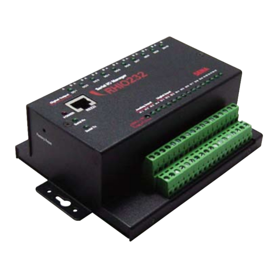
2.1 Panel Layout The Rhio232 has LED indicator lamps for status display. The lamps in the left hand side indicate the system power-on status, Serial Rx and Serial Tx for RS232 communication status. There are 10 lamps for displaying digital output status, 12 lamps for digital input status, and lamps for 4 analog port status. - Page 10 Figure 2-1. The panel layout of the Rhio232 Table 2-2. Terminal Block Assignment of the Rhio232 DI10 DI11 DI12 • Power Input ( PWR_A , PWR_B ): (1,2) • Analog reference voltage ( Ref ) : (3) -It is analog reference voltage input block. Rhio represents voltage from 0 V to a reference voltage in 1,024 steps.
-
Page 11: Connecting The Hardware
2.2 Connecting the Hardware 2.2.1 Setting up DIN Rail mount kit Users may use DIN rail mounting kit included in the package to install the Rhio232 on to the DIN rail. Figure 2-2. Dimension of DIN Rail mount kit and applicable DIN Rails... -
Page 12: Connecting The Power
Figure 2-4. Setting up the Rhio232 to DIN Rail 2.2.2 Connecting the Power Supply the proper power according to the power specification of the Rhio232, i.e. 9V~48VDC, MAX. 5W. If the power is properly applied, [Power] indicator will maintain RED. Be sure not to use the cable longer than 3m for normal operation. -
Page 13: Connecting To The Serial Device
2.2.3 Connecting to the serial device Connect the one end of the CAT5 cable to RS232 port of the Rhio232 and the other to host or device server. If connector type of host or device server is DB9, connect the other end using RJ45 to DB9 Female adaptor. -
Page 14: Basic Configuration Using Rhio Manager
Figure 2.7 Rhio Manager screen layout 2.3.2 Basic configuration using Rhio Manager Select Interface It specifies the communication method between the Rhio232 and Rhio Manager. Be sure to set it up as “Serial” mode. Quick Connect By using [Quick Connect], user can select the RS232 serial port that is connected to the Rhio232. -
Page 15: Restoring Factory Default
Users may restore the Rhio232 parameters into factory default value by pressing factory reset switch on the hole of the Rhio232 side panel. They will have to put the sharp pin into the hole and press it for around 1 sec to reset the Rhio232. The Rhio232 will be rebooted after the operation. -
Page 16: I/O Setting And Application
You can monitor, control and set I/O states by pressing the [I/O PORT CONTROL] button. Once [I/O PORT CONTROL] is invoked, Rhio Manager begins to monitor the I/O state by connecting to a serial port of the Rhio232 via a RS232 serial interface. 3.1.1 LED... -
Page 17: Specifying Monitoring Interval
3.1.2 Specifying monitoring interval You can continue to monitor the I/O state of the Rhio232 at a specified time interval by setting [Setting Monitor Interval]. The valid value for monitoring intervals is any number between 2 and 10 seconds. In the specified time interval, Rhio Manager sends a state request command and receives a response from the Rhio232 and displays it on the screen. -
Page 18: Digital Input Setting
When the operation condition is specified, the port is set to ON if it is met, and it is set to OFF and displayed as a standby state if not. After output control is completed, the Rhio232 returns the states of all ports to the host computer. -
Page 19: Digital Output Port Setting
3.3 Digital Output Port Setting The Rhio232 has 10 digital output ports. You can set each of these digital output ports with Rhio Manager or by issuing the commands specified in "Ch. 4 I/O Port Related Protocols". Place your mouse cursor over the Digital Output Port LED on the I/O Port Control screen and right-click it to display the Setting Output Port window. -
Page 20: Setting Run Condition
3.3.2 Setting run condition When the [Macro] check box is selected, you can enter a conditional expression and then use it to control operation of an output port. Enter the desired conditional expression in the [Macro] box. Specify an operation condition for each output port. An output port that has not been set is regarded as a port available for direct control. -
Page 21: Delay & Pulse Operation
If it is disabled, the output port state becomes OFF when power goes out and back on. 3.4 ADC Input Port Setting The Rhio232 has 4 ADC input ports. You can set an ADC input port with Rhio Manager or by issuing commands via an I/O port protocol (refer to "Ch.4 I/O Port Related Protocols”). -
Page 22: Setting Reference
Figure 3-5 Setting ADC Input Port 3.4.1 Setting Reference Specify a reference voltage for analog input data. Rhio represents voltage from 0 V to a reference voltage in 1,024 steps. A reference voltage may not exceed 5 V. Specify a reference voltage in the Reference list box. -
Page 23: I/O Port Connection
This section describes how to make a required connection with the digital output, digital input and ADC input port of the Rhio232 for the users’ devices. The length of cables used for I/O port connection should be less than 3 meters to ensure normal operation. -
Page 24: Adc Input Port
Figure 3-7 Connection of Digital Input Port 3.5.3 ADC Input Port An ADC input port is a non-insulated input port. If possible, a circuit should be made using AVCC (+5V) voltage supplied from internal circuits. When operating in Switch mode, a threshold voltage should be specified. - Page 25 2) When using an Analog Input Potentiometer An analog input operates in reference to input voltage and has an impedance of 100㏀. When using a Potentiometer as shown in Figure 3-9, an impedance in the range of 1㏀ - 5㏀ is ideal. When using an external signal source, lower impedance ensures stable operation against various noises.
-
Page 26: Software Development & Application
4. Software Development & Application You can use the Rhio library to develop application software that is used to communicate with the Rhio232. The Rhio Library Files RHIO_Proc.dll, RHIO_Process.h You must link these two files in order to develop software using the Rhio library. - Page 27 2) Structure (See Appendix C.2) Structure Description SADCData ON/OFF state of each port SOnOffStateData ON/OFF state of all ports SSetOutput Output port configuration information SSetADC ADC configuration information SSetInput Input port configuration information SRHIOSetting All ports configuration information 3) Function (See Appendix C.3) Function Description A function that creates Process Class that...
- Page 28 Send a command that checks enable/disable RHIO_SndCmd_GetPortEnable state of all ports. Send command that enables/disables RHIO_SndCmd_SetPwrStopEnable power-out recovery for all ports. Send a command that checks enable/disable RHIO_SndCmd_GetPwrStopEnable state of power-out recovery for all input ports. RHIO_SndCmd_SetFactoryReset Send Rhio Factory Reset command. RHIO_SndCmd_SetSerial Send a command that sets Rhio serial number.
-
Page 29: Creating And Demonstrating A Sample Program With Rhio Library
4.2 Creating and demonstrating a sample program with Rhio library The sample program (RHIO_TEST) is a dialog box based application that has been created with Microsoft Visual Studio .NET linked to Rhio library (RHIO_Proc.dll,RHIO_Process.h). 4.2.1 Program UI Configuration and their related classes Figure 4-1 Main Window of a Sample Program Class Related Files... -
Page 30: Processing
Figure 4-2 Setting Window of a Sample Program Class Related Files CSettingDlg SettingDlg.h SettingDlg.cpp 4.2.2 Processing 4.2.2.1 Initializing Main window 1) Link the library and get the address of a required library function. CWEB_IO_TESTDlg::RHIODllLoad() 2) Initialize dialog items in Main window. CWEB_IO_TESTDlg::InitOutPutButton();... - Page 31 CWEB_IO_TESTDlg::InitSample(CPoint pntStart, int iWidth, int iHeight, int iTerm) CWEB_IO_TESTDlg::InitSelComm(); 3) Create Process Class. m_rhCreate(CWnd *pParentWnd) 4.2.2.2 Event Handling procedure When an event occurs in the main window of the program: ① The Connect button is clicked on. CWEB_IO_TESTDlg::OnBnClickedButtonConnect() TCP Connection m_rhSockConnect (BYTE bAddr1, BYTE bAddr2, BYTE bAddr3, BYTE bAddr4, int iPort) ...
- Page 32 ⑥ The Monitor Power Stop button is clicked on. CSettingDlg::OnBnClickedButtonMonitorPwrStop() ⑦ The Set Power Stop button is clicked on. CSettingDlg::OnBnClickedButtonSetPwrStop() ⑧ The Monitor Enable State of the Port button is clicked on. CSettingDlg::OnBnClickedButtonMonitorEnable() ⑨ The Enable Port button is clicked on. CSettingDlg::OnBnClickedButtonSetEnable() ⑩...
-
Page 33: Rhio Communication Protocol
4.3 Rhio Communication Protocol In this chapter, it covers how to send/receive the command/reply to/from Rhio device by using the Rhio communication protocol. 4.3.1 Overview You can use the Rhio communication protocol to set, control and monitor RHIO. 4.3.1.1 Command Block START LENGTH FUNCTION... - Page 34 - LRC (BCC) It checks the Error of the command block. The value by 1 byte XOR from LENGTH field to DATA field - END FLAG CR+LF ( 0x0D+0x0A ) -. The data of LENGTH and LRC is expressed as follows. Each 4-bit nibble (upper 4-bit nibble and lower 4-bit nibble) is expressed as 1 Byte data.
-
Page 35: On/Off Control
- NAK Response START LENGTH FUNCTION DATA FLAG (BCC) FLAG Byte Size Start of the The length from Response from CR (0x0D) “00” Command FUNCTION field Data LENGTH LF (0x0A) “NAK” Block, 0x3A to DATA field 0x30,0x30 field to DATA ( “:”... - Page 36 Data MASK Data Data Separator ON/OFF Data Data Order 1 - 10 12-21 Port No. 1 - 10 1-10 0x2C ( “,” ) Control: 0x31 ON: 0x31 Data Content separates MASK Non-control: 0x30 OFF: 0x30 from ON/OFF. MASK and ON/OFF Data correspond to one port per byte for each port in sequence. Port location by Data Order Data Order...
- Page 37 0x30: OFF, “0000”-”1023”: 8-12 0x31: ON (Switch Input), Level 0x39: Level Mode Field Separator 0x2C ( “,” ) 0x30: OFF, “0000”-”1023”: 14-18 0x31: ON (Switch Input), Level 0x39: Level Mode Field Separator 0x2C ( “,” ) 0x30: OFF, “0000”-”1023”: 20-24 0x31: ON (Switch Input), Level 0x39: Level Mode...
-
Page 38: Input/Output State
0x31: Run and Run Modes. Set/Run The Rhio232 returns a state response once after set command is received. It does not return any state response until it receives run command even if it is switched to Setting mode. When setting output port, ADC input port, Port Enable, Port Power-out Recovery or serial number, send set command first to switch it to Setting mode. -
Page 39: Output Port Setting
4.3.4.2 Response for Set/Run command Same as "4.3.2.2 Response for ON/OFF control". In Setting mode, the Rhio232 returns a response once and it does not respond until run command is received. The control state field of the state response, the Rhio232 returns 0x31 in Setting mode and 0x30 in Run mode. - Page 40 A conditional operator + Input/Output port state (NOT) AND => &, OR => |, NOT => ! A conditional expression only takes the form of a single expression with AND, OR, NOT. Eg. AND operation of Input #1 and Input #2 : I1 &...
- Page 41 “00000” “00020” OFF after 2 sec delay “00000” “50000” OFF after 5,000 sec delay “00001” “00001” Repeat 100 ms ON and 100 ms OFF. “00020” “00020” Repeat 2 sec ON and 2 sec OFF. Repeat 5,000 sec ON and 5,000 sec “50000”...
-
Page 42: Adc Input Port Setting
4.3.5.4 Response for Check Output Port Setting command Same as "4.3.5.2 Response for Set Output Port command". 4.3.6 ADC Input Port Setting 4.3.6.1 Set ADC Input Port Command Command Data Remark Byte Size Set the threshold “08” level value for an Set it to a 10-bit ADC ( 0x30, 0x38 ) input ADC port. -
Page 43: Port Enable Setting
Setting Flag 0x30: Set OK 0x31: Not in Setting mode (in Run mode) 0x39: Set NG 4.3.6.3 Check ADC Input Port Setting Command Command Data Remark Byte Size “10” Check the ( 0x31, 0x30 ) 0x30: Fixed to a dummy threshold level Check the ADC value... - Page 44 Field Separator 0x2C ( “,” ) 0x30: AVcc ( Vcc 5V ) -> default 0x31: Internal ( 2.56V ) ADC Reference 0x32: External ( 2-4.5V ) Setting Field Separator 0x2C ( “,” ) 8-11 I1-I4 0x31: Enable, 0x32: Disable Field Separator 0x2C ( “,” ) 13-16 I5-I8 0x31: Enable, 0x32: Disable...
- Page 45 0x30: Avcc ( Vcc 5V ) -> default 0x31: Internal ( 2.56V ) ADC Port 0x32: External ( 2V-4.5V ) Field Separator 0x2C ( “,” ) 0x30: Avcc ( Vcc 5V ) -> default ADC Reference 0x31: Internal ( 2.56V ) Setting 0x32: External ( 2V-4.5V ) 9-12...
-
Page 46: Port Power-Out Post Recovery Setting
4.3.8 Port Power-out Post Recovery Setting 4.3.8.1 Set Port Power-out Post Recovery command Command Data Remark Byte Size “14” Set Power-out ( 0x31, 0x34 ) The Port Power-out Post Post Recovery to Set Power-out Post Recovery setting data Enable/Disable Recovery to for an output port Enable/Disable. - Page 47 0x31: Enable, 0x32: Disable O1-O4 Field Separator 0x2C ( “,” ) Output State 7-10 O5-O8 0x31: Enable, 0x32: Disable Field Separator 0x2C ( “,” ) 12, 13 O9, O10 0x31: Enable, 0x32: Disable 4.3.8.3 Check Port Power-out Post Recovery Setting command Command Data Remark...
-
Page 48: How To Use The Rhio232 With Device Servers
RJ45. Users should use RJ45-DB9 female straight adapter in the package in order to connect the Rhio232 to the Sena device servers that has DB9 serial port, i.e. LS100, PS100. Users may directly use CAT5 straight cable to connect it to the Super series or STS series models that have RJ45 serial port. -
Page 49: Application
CAT5 straight cable SS110/400/800 STS800/1600 5.2 Application This chapter covers how to test the Rhio232 with the Sena’s 8-port device server, SS800 by using Serial/IP software. The following is the units required to test and the corresponding configurations for each module. - Page 50 It is assumed that Serial/IP COM Port Redirector and Rhio Manager software are already installed on the users’ PC and that the Rhio232 is connected to the appropriate I/O devices. Figure 5-1 shows the application diagram of the SS800 with the Rhio232.
- Page 51 Step 1. Connect the Rhio232 to the port #1 of the SS800 using CAT5 cable. Step 2. Serial/IP Configuration Double click the Serial/IP Tray application and then select COM10 as a virtual serial port after clicking [Select Ports] on the panel.
- Page 52 Click the [Configuration Wizard] button on the Serial/IP Control Panel. Complete COM port setting by clicking [Start] button on the Configuration Wizard panel. Close the window by clicking [Use Setting] button after the communication test.
- Page 53 Run the Rhio Manager and then select [Serial] for communication type. Configure COM port after clicking [Probe] button the toolbar Users can now connect to the Rhio232 which is connected to the SS800 by way of the SS800.
- Page 54 Click the [I/O CONTROL] button and then it will open Rhio Manager I/O management panel. Users can remotely control and monitor the I/O devices connected to the Rhio232 through the COM10 port of the PC. Users can remotely manage the I/O devices by using such components as Serial/IP, SS800 and Rhio232.
-
Page 55: Appendix A. Connection
Appendix A. Connection A.1 Serial Port Pin Outs The pin assignment of the RHIO232 RJ45 connector is summarized in Table A-1. Each pin has a function according to the serial communication type configuration. Note : When connecting serial port to host, users should use the other end of CAT5 cable using RJ45 to DB9 Female connector(included package). -
Page 56: Serial Port Wiring Diagram
A.2 Serial Port Wiring Diagram Figure A-5. RS232 serial port wiring diagram... -
Page 57: Appendix B Troubleshooting
Appendix B Troubleshooting B.1 Power/LED Status Troubleshooting Problem Cause Action Power LED does not Power cable is not Check power connection. The Rhio232’s power light up connected specification is DC 9V~48V. Serial Rx LED does Serial cable Check serial cable connection... -
Page 58: Appendix C. Rhio Linrary
Appendix C. Rhio Linrary C.1 Enumeration Type EOnOffFlag Flag for ON, OFF, Operation condition enum EOnOffFlag EOF_ON, //ON status EOF_ON_ADC_LEVEL, //ADC Level ON status EOF_OFF, //OFF status EOF_NOT, // Status uncertain status EOF_ON_DELAY, //Delay ON waiting status EOF_OFF_DELAY, //Delay OFF waiting status EOF_ONOFF_MACRO, //Macro(condition) waiting status EOF_ONOFF_PULSE... - Page 59 ESF_SET_FACTROT_RESET, //Factory Reset Command transfer status ESF_SET_SERIAL, //Serial number Set Command transfer status ESF_MON_MACRO, //Macro check Command transfer status ESF_MON_DELAY_PULSE, //Delay/Pulse check Command transfer status ESF_MON_ADC, //ADC check Command transfer status ESF_MON_ENABLE, //Enable/Disable check Command transfer status ESF_MON_PWR_STOP, //Power-out Post Recovery check Command transfer //status ESF_MON_SERIAL, //Serial number check Command transfer status...
-
Page 60: Structure
C.2 Structure ON/OFF status Data Structure which contains Port ON/OFF status typedef struct _ADCData //ADC Data EOnOffFlag eADC; //ADC On/OFF Flag char cADC[5]; //ADC Level storage }SADCData; typedef struct _OnOffStatusData //All Port ON/OFF Data EOnOffFlag eOutput[10]; //Output Port 1~10 EOnOffFlag eInput[12]; //Input Port 1~12 SADCData sADC[4];... -
Page 61: Function
SADCData sADCData[4]; //ADC Level Data }SSetADC; typedef struct _SetInput //Input Port Set Data bool isEnable[12]; //Input port Enable }SSetInput; typedef struct _RHIOSetting //All Port Set Data SSetOutput sOutput; //Setting Output port Data; SSetADC sADC; //Setting ADC port Data; SSetInput sInput; //Setting Input port Data;... - Page 62 RHIO_SockConnect Description : Used when users want to connect to RHIO using TCP Socket connection. Function Prototype : extern "C" __declspec(dllexport) bool RHIO_SockConnect (BYTE bAddr1, BYTE bAddr2, BYTE bAddr3, BYTE bAddr4, int iPort); Parameter : BYTE bAddr1 : 1st byte of the IP Address BYTE bAddr2 : 2nd byte of the IP Address BYTE bAddr3 : 3rd byte of the IP Address BYTE bAddr4 : 4th byte of the IP Address...
- Page 63 RHIO_Close Description : Used when users want to disconnect the current connection with the Rhio in both serial and TCP connection. In order to reconnect to the Rhio, be sure to use Rhio-Close function before connection attempt. Function Prototype : extern "C"...
- Page 64 RHIO_SndCmd_GetOnOff Description : Used to send the command to get ON/OFF status of all the ports Function Prototype : extern "C" __declspec(dllexport) bool RHIO_SndCmd_GetOnOff(); Parameter : None Return : TRUE if successful, False if failed. eg. : RHIO_SndCmd_GetOnOff(); RHIO_SndCmd_SetSettingMod Description : Used to send the command to switch to the Set Mode. Function Prototype : extern "C"...
- Page 65 RHIO_SndCmd_SetMACRO Description : Used to send the command to set/clear the MACRO of an input port Function Prototype : extern "C" __declspec(dllexport) bool RHIO_SndCmd_SetMACRO (SRHIOSetting sSetData, int iPortNum); Parameter : SRHIOSetting sSetData : Data to set SRHIOSetting.sInput.eMacro : Flag to determine to set or clear (ESOF_CLEAR, ESOF_SETTING) SRHIOSetting.sInput.cMacro : MACRO string int iPortNum : Input port number to set...
- Page 66 RHIO_SndCmd_GetMACRO Description : Used to send the command to check whether it is possible to get the MACRO of an input port Function Prototype : extern "C" __declspec(dllexport) bool RHIO_SndCmd_GetMACRO (int iPortNum); Parameter : int iPortNum : Input port number to check Return : TRUE if successful, False if failed.
- Page 67 Parameter when reaction event is received : WPARAM : Command transfer status flag (ESF_SET_DELAY_PULSE) LPARAM : Control status flag of the command (False if Time Out Error) (0x30:Normal operation, 0x39:Abnormal operation, 0x31:Not the Set Mode, 0x32:Not set) eg. : In case of Set command : SRHIOSetting sSetData;...
- Page 68 RHIO_SndCmd_SetADC Description : Used to send the command to set the Level of all the ADC ports from 1 to 4. Function Prototype : extern "C" __declspec(dllexport) bool RHIO_SndCmd_SetADC (SRHIOSetting sSetData); Parameter : SRHIOSetting sSetData : Data to set SRHIOSetting.sADC.sADCData[index].cADC : ADC Level string in 4 bytes between "0000"...
- Page 69 (0x30:Normal operation, 0x39:Abnormal operation, 0x31:Not the Set Mode) ※ When reaction event is received, get data using RHIO_GetSettingData function and check the Level on setting. eg. : RHIO_SndCmd_GetADC(); RHIO_SndCmd_SetPortEnable Description : Used to send the command to enable/disable all the ports. Function Prototype : extern "C"...
- Page 70 RHIO_SndCmd_GetPortEnable Description : Used to send the command to check whether it is possible to get the Enable/Disable Port data of all the ports Function Prototype : extern "C" __declspec(dllexport) bool RHIO_SndCmd_GetPortEnable(); Parameter : None Return : TRUE if successful, False if failed. Parameter when reaction event is received : WPARAM : Command transfer status flag (ESF_MON_ENABLE) LPARAM : Control status flag of the command (False if Time Out Error)
- Page 71 RHIO_SndCmd_GetPwrStopEnable Description : Used to send the command to check whether it is possible to get the Enable/Disable Power Failure Recovery of all the input ports Function Prototype : extern "C" __declspec(dllexport) bool RHIO_SndCmd_GetPwrStopEnable(); Parameter : None Return : TRUE if successful, False if failed. Parameter when reaction event is received : WPARAM : Command transfer status flag (ESF_MON_PWR_STOP) LPARAM : Control status flag of the command (False if Time Out Error)
- Page 72 CString strSerial : Serial number string limited to 12 bytes Return : TRUE if successful, False if failed. Parameter when reaction event is received : WPARAM : Commnad transfer status flag (ESF_SET_SERIAL) LPARAM : Control status flag of the command (False if Time Out Error) (0x30:Normal operation, 0x39:Abnormal operation, 0x31:Not the Set Mode) eg.
- Page 73 RHIO_GetSettingData Description : Used to send the command to get the setting data corresponding to the command transfer status flag Function Prototype : extern "C" __declspec(dllexport) bool RHIO_GetSettingData (SRHIOSetting &sSetData); Parameter : SRHIOSetting &sSetData : Data to get Return : TRUE if successful, False if failed. eg.
-
Page 74: Appendix D. Warranty
(a) any misapplication or misuse of the Product; (b) failure of Customer to adhere to any of SENA’s specifications or instructions; (c) neglect of, abuse of, or accident to, the Product; or (d) any associated or complementary equipment or software not furnished by SENA. -
Page 75: Hardware Product Warranty Details
All replaced Product and parts become the property of SENA. If SENA determines that the Product is not under warranty, it will, at the Customers option, repair the Product using current SENA standard rates for parts and labor, and return the Product at no charge in or out of warranty. -
Page 76: Software Product Warranty Details
WARRANTY PERIOD: SENA warranties software Product for a period of one (1) year. WARRANTY COVERAGE: SENA warranty will be limited to providing a software bug fix or a software patch, at a reasonable time after the user notifies SENA of software non-conformance.
Need help?
Do you have a question about the Rhio232 and is the answer not in the manual?
Questions and answers