
Related Manuals for Delem DA-66T


Summary of Contents for Delem DA-66T
- Page 1 DA-66T Reference Manual Operation of Version 2.3 English 8075-9000A Manual version V0913...
- Page 2 Preface This manual describes the operation of the Delem control type DA-66T and is meant for oper- ators who are instructed for operation of the total machine. Delem Limited warranty • This manual does not entitle you to any rights. Delem reserves the right to change this manual without prior warning.
-
Page 3: Table Of Contents
Table of contents 1. Operation overview and general introduction ....1.1 1.1. The control unit ........... . 1.1 1.2. - Page 4 The DXF file ........... 2.24 3.
- Page 5 7.2.1. Main ............7.6 7.2.2.
- Page 6 10.2.5. Air + hem bend punch ........10.12 10.2.6.
-
Page 7: Operation Overview And General Introduction
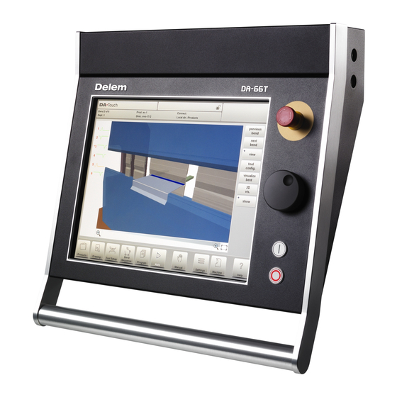
Operation overview and general introduction 1.1. The control unit The control looks as follows: The precise outfit of your control may vary. Operation of the control is mainly done over the touchscreen. A description of the functions and available touch controls is given in the next sections of this manual, aside of the description of the specific functions. -
Page 8: Front Control Elements
1.2. Front control elements The frontpanel, beside display, consists of the following control elements: Emergency stop button, to be implemented by machine manufacturer. Handwheel; manual control of any axis (Y + backgauge axes) Start button Stop button V0913, 1.2... -
Page 9: Usb Connectors
1.3. USB connectors At the right side of the control two USB ports are available for connection of external devices, such as memory sticks or an external keyboard / mouse. V0913, 1.3... -
Page 10: Operation And Programming Modes
1.4. Operation and programming modes The DA-Touch control's main screen looks as follows: Depending on the navigation button which is active, the screen will differ. The above main screen will appear having the Products function active. Just by tapping the various modes, the specific mode will be selected. The structure of the main screen is as follows: Title panel In the top the title panel is always shown. - Page 11 Information panel In the information panel all functions and visualisation related to the selected modus are displayed and can be found. Command panel The command panel is part of the Information panel and is the location where the controls related to the Information panel can be found. Navigation panel The Navigation panel is the area where all the major modes can be found.
- Page 12 Explanation of the main modes / navigation buttons To make a new program and select a program out of the product library. To draw/create a new product or edit an existing product (graphically). To setup the machine and modify existing tool setups. To compute and modify the bend sequence.
-
Page 13: Getting Started
1.5. Getting started 1.5.1. Introduction In order to obtain a bend program for a product, the control offers the possibility to create a product drawing and calculate a valid bend sequence for the product. With this information, a product program is generated. This is done with the following steps: Go to the Products mode in the navigation panel and start a new product by tap- ping New Product. - Page 14 Value Setting Once the product or tool is drawn in the Sketching method the exact values of line lengths and angles can be optimized by the Value setting method. Just tap 2 times on the value of the line length or angle to change and the keyboard will pop-up. The value can be entered in 2 ways of confirmation: •...
-
Page 15: Determine Bend Sequence
1.5.4. Determine bend sequence When the product drawing is completed, the control offers Tool setup mode to program the exact tool set-up as it is organised on the machine. After this you can select the Bend Sequence mode to determine and simulate the required bend sequence. In the Bend Sequence mode, the control shows the product, the machine and the tools. -
Page 16: The Auto Menu And Manual Menu, Production Modes
Both product and tool files can be stored externally. Depending on the configuration, these files can be stored on a network or on a USB storage device. This facilitates a back-up of important data and the possibility to exchange files between Delem controls. More information about this can be found in chapter 9. -
Page 17: Programming Aids
1.6. Programming aids 1.6.1. Help text This control is equipped with an on-line Help function. When the Help-button in the navigation panel is pressed context sensitive help will be provided. To activate a help window for a parameter tap the Help button in the navigation panel. A pop-up window appears with information on the active parameter. -
Page 18: Listbox Functionality
1.6.2. Listbox functionality Several parameters on the control have a limited number of possible values. When selecting such a parameter, by tapping the parameter line on the screen, the list of options will open up near the position where you tapped the line, and the desired value can be selected. To undo the selection and the opened listbox, tapping outside the box will make it close without changing the selected parameter. -
Page 19: Navigation
1.6.4. Navigation Within some modes, the program screens are divided into tabs. The tabs can easily be selected by just tapping them. When a tab is not completely visible or not visible at all, just by dragging the tab row horizontally, the desired tab can be "pulled" in sight and be selected. -
Page 20: Typing Alphanumeric Characters Vs. Special Characters
1.6.5. Typing alphanumeric characters vs. special characters Both alphanumeric characters and special characters can be used throughout the control. A full on-screen alphanumerical keyboard will pop up when required. When editing a field which is pure numeric, the alphanumeric characters will be "greyed-out" and only the numerical keypad can be used. -
Page 21: Network
1.6.6. Network The CNC control is equipped with a network interface. The network function offers the operators the possibility to import product files directly from the network directories or to export the finished product files to the required network directory. Chapter 9 about backup/restore in Settings mode contains more information about networking possibilities. -
Page 22: Keylock Function
1.6.7. Keylock function To prevent for changes to products or programs, the keylock function offers the possibility to lock the control. In the locked state, only a product can be selected and executed in Auto mode. To lock a control just tap the lock symbol in the top of the screen. Lock symbols will also appear behind parameters to show the lock is active and modification is not possible. -
Page 23: Oem Function Panel
Codes can be changed upon desire. The procedure to manages codes can be found in the Installation manual. 1.6.8. OEM function panel Depending on machine manufacturers implementation, the upper right corner of the screen can be used for special indicators. To access functions related to those indicators, the OEM function panel can be opened by tapping this corner of the screen. -
Page 24: Software Versions
1.6.9. Software versions The version of the software in your control is displayed at the System Information tab in the Machine menu. Example of version number: V 1.2.3 V stands for version V 1.x.x is the major version number V x.2.x is the minor version number V x.x.3 is the update version number The major version number is increased when new major features are added to the software. -
Page 25: Products, The Product Library
Products, the product library 2.1. Introduction In the Products mode existing, previously produced, products can be selected to start production or for modification in order to make a similar product. To start making a new product or program New Product or New Program can be used from this mode. 2.1.1. -
Page 26: Product Selection
the product has a CNC program, there is no drawing the product consists of a 2D drawing, there is no CNC program the product has a 2D drawing and a CNC program the product consists of a 3D drawing, there is no CNC program the product has a 3D drawing and a CNC program If a product program is already active its ID is shown in the top of the screen. -
Page 27: New Product, Starting A New Graphical Product
2.1.3. New Product, starting a new graphical product To start a new graphical product tap New Product. After New Product is chosen, the programming of a new product starts with its general details like Product ID, Thickness and Material. V0913, 2.3... -
Page 28: New Program, Starting A Numerical Program
2.1.4. New Program, starting a numerical program To start a new numerical program tap New Program. After New Program is chosen, the programming starts with its general details like e.g. Product ID, Thickness and Material. The shown general tab is next to the successive tabs which are ready for programming the first bend. -
Page 29: Views
2.1.5. Views To view the products as a simple list, or completely graphical the View function can be used. By tapping View one of the three view modes can be selected. V0913, 2.5... - Page 30 V0913, 2.6...
-
Page 31: Edit, Copying And Deleting A Product Or Program
2.1.6. Edit, Copying and Deleting a product or program To delete a product in the Products mode select a product by tapping it. It will be selected. After that tap Edit and use Delete. To finally delete it confirm the question. To delete all products and programs at ones, tap Delete All. -
Page 32: Filter Function
2.1.7. Filter function To make finding products easier the filter function enables live searches through-out the Products mode. When tapping Filter, the filter screen will show. By typing the desired filter string, optionally devided by spaces, the live search will start. Optionally a different view can be selected. -
Page 33: Change Directory
Tap Make Subdir and enter the new name. Subdirectories are called subdirectories because these directories reside under the local directory 'DELEM\PRODUCTS'. The name of the subdirectory cannot be changed. In this menu it is not possible to copy products from one subdirectory to another subdirectory;... -
Page 34: Network Product Selection
2.1.9. Network product selection When a networkdirectory has been mounted in the control this mounted directory can be found under Network. Network is available next to the Product directory when using change directory. The name of the mounted drive indicates availability for product selection and storage. -
Page 35: The Dxf Import Option
CAD-system output file. This chapter will explain the use of the DXF converter to import DXF files and its functionality. (This functionality is optionally available in the DA-66T for 2D products only) The DXF import option is started with the command button above New Product. Import DXF opens a file selection browser to select the DXF file. - Page 36 For the DXF file to be imported it is advised to create the original drawing as accurate as possible. Bend lines should be connected to contour lines to obtain an accurate product drawing. If this is not the case, the DXF Converter can correct small errors. After selecting the DXF file the DXF import function window will open showing the DXF file.
-
Page 37: Product Drawing Dimensions
2.2.1. Product drawing dimensions The drawing file can be organised in two ways: • projection dimensions; • cutting dimensions. These ways are described in the following subparagraphs. During operation in the DXF converter, it is possible to switch between cutting dimensions and projection dimensions. -
Page 38: Bendlines And Layer Selection With Line Assignment
2.2.2. Bendlines and Layer selection with Line assignment For a proper conversion, the assignment of specific product properties to lines in the DXF is important. Depending on the content of the DXF, the bendlines, contour and additional text information can be assigned layer by layer. In case layer selection is set off, the bendlines are being searched for automatically. -
Page 39: Layer Selection Switched On
Layer selection switched on With layer selection on, the available layers in the DXF are shown in the list. In the header the symbols of angle, contour, text and visualisation are shown and indicate the layer assignment. Each layer can be assigned to the specific property column by checking a checkbox. -
Page 40: Layer Selection Switched Off
Layer selection switched off If layer selection is off, the control will automatically assign line properties. Line properties can only be viewed (length) not changed. After selecting a line, the property command button will appear. Colors shown are the colors from the original DXF. V0913, 2.16... -
Page 41: Line Select
Line select In the window of the DXF converter lines can be selected, by tapping on these lines, and selections can be inverted. When dragging a box over multiple lines, multiple lines can be selected at ones. Dragging from upper left to lower right will only select lines completely covered by the selection box. -
Page 42: Conversion
2.2.3. Conversion When the assignments have been set properly, conversion can be executed by tapping the Convert button. The conversion preview will be shown when there are warnings or errors. During conversion the DXF drawing is represented by lines like contour line, bend line and inside contour lines. -
Page 43: Product Properties
Product Properties After accepting the preview, converted Product Properties will be shown and can be modified. By accepting and closing this window the actual conversion will take place. The result of the conversion is shown in Drawing. One can continue with the tool set-up and bend sequence determination as with a product drawn by hand. -
Page 44: Converting Cutting Dimensions, With Bend Allowance Info
2.2.4. Converting cutting dimensions, with bend allowance info At the last stage of converting a DXF with cutting dimensions, the bend allowance which has been used during unfolding, needs to be reused in the conversion. Therefore the conversion of cutting dimensions will always use the bend allowance table of the control and it will check if for all bends bend allowance information is available. - Page 45 V0913, 2.21...
-
Page 46: Dxf Settings
2.2.5. DXF Settings In the DXF converter settings the conversion parameters can be configured. It is possible to store multiple settingsfiles for specific drawing types. Save as and load functions are available. Conversion parameters Default angle Bendlines not being indicated with a bending angle value will be converted with this default angle. -
Page 47: Labels
Layer selection Layer selection on / off to enable the assignment of conversion properties by layer. Labels Linetypes and product properties can be labelled within the DXF in order to automatically assign them. With these settings the labels can be configured. Control codes If specific control codes are used in the DXF text, in this settings window these codes can be configured. -
Page 48: The Dxf File
The DXF file The DXF converter reads the entities it knows from the DXF file. The entities are: Text, Mtext, Line, SPLine, 3D, Line, Polyline, LWPolyline, Arc, Circle, 3D face, Solid, Trace and Insert. Furthermore: • The converter can handle ECS co-ordinates. Note: ECS is used in 3D drawings, so the converter interprets the values of the ECS for 2D. -
Page 49: Product Drawing
Product drawing 3.1. General product properties To edit an existing product drawing, choose the specific product from the Product library and select Drawing. To start a new product drawing, choose New Product in the product library When a new product drawing is started a screen with general product properties appears. First these properties, general data, should be set before starting with the product drawing. - Page 50 Product ID A unique name to identify a product program. The maximum length is 25 characters. The product ID may contain letters and numbers as available on the keyboard. Product description A name or description of this program. The maximum length is 25 characters. The product description may contain letters and numbers.
- Page 51 To change the active directory select Change Directory. The current product is automatically copied to the new directory V0913, 3.3...
-
Page 52: Add Notes
3.1.1. Add Notes When Edit Notes has been pressed, a new window appears in which you can edit the text about the current product. The possible characters are displayed on the keyboard. To attach a PDF file to the note tap Attach PDF. Via the directory browser a PDF file can be selected and will be incorporated in the product file. -
Page 53: Product Drawing
3.2. 2D product drawing 3.2.1. Introduction After entering the general product data the drawing screen appears. In the upper information row you will find the information about product ID, product description, inside/outside dimensions selection and actual product directory. Now you can create the profile of the product. It is possible by using your fingers to tap and create quickly the product in 'sketch' mode. - Page 54 The currently active element (line or angle) is highlighted. In a product drawing you can program up to a maximum of 99 bends per product (graphical programming). When the product drawing is finished it is possible to navigate to the next step in the programming process;...
-
Page 55: Line Properties
3.3. Line properties 3.3.1. Introduction When the cursor is on one of the product lines it is possible to change the properties of that line by selecting Properties. 3.3.2. Projection Inside the window with line properties, the following projection properties can be programmed: Horizontal projection The horizontal distance a line must measure, regardless of its angle value. -
Page 56: Precision Selection
or vertical projection distance and press Enter. The required line length is computed and applied to the selected segment. is normal entered line length is vertical projected line length is horizontal projected line length It will be noted on the screen if projection is not possible. 3.3.3. - Page 57 Line interval marked with the open circle should be, if possible, directly placed between back stop and the centre of the die. Notes Specifying line intervals with high precision and closing dimensions may result in longer production time. The precision parameter will have priority over the "front extend ratio", if that is set to "comply if possible".
-
Page 58: Bend Properties
3.4. Bend properties 3.4.1. Air bend Drawing a product graphically is simply programming the line length, angle value, next line length, etc. till the product has its required shape. The bends in the product have their standard or specific properties. The bend properties can be set by selecting the bend and selecting Properties. -
Page 59: Large Radius: Bumping
A large radius is meant to be bent with a special radius punch with large radius. If such a punch is not available, the bumping method can be selected. The radius value may not exceed the length of any adjacent sides. For the definition of the line lengths to be programmed in the part connected to a radius bend, see figure below. - Page 60 First you can choose the Angle Definition. The available definitions are: • The default angle is the angle which could be programmed as standard. • The central angle is the supplement of the default angle (i.e. 180 degrees - default angle).
-
Page 61: Hem Bends
• Enabled (equal sizes) When Enabled all segments will have an equal size. When Disabled the calculation is including half size segments. If in this case a problem with the size of the V die is detected in the bend sequence determination, the user is asked whether or not to select a re-calculation with equally sized segments. - Page 62 the best practical value, the default value is 30 degrees. Hem opening The hem bend can be made with a certain opening distance between the 2 flanges. The hem opening value will be used calculating the beam position in the hemming process. By default this parameter has the value of the Settings mode parameter Default Hem Opening.
-
Page 63: Tool Configuration
Tool configuration 4.1. Introduction To edit or modify a tool setup for the product, select the product from the library and use Tool Setup 4.2. Standard procedure When the function Tool Setup has been activated, the screen shows a front view of the machine set-up in the upper half of the screen. -
Page 64: Tool Selection
4.3. Tool selection When starting a new tool configuration, the machine opening is empty. Select Add to add a tool to the configuration; punch, die or adapter (if enabled). When a tool has been chosen (e.g. a punch), it is placed in the machine with maximum available length. - Page 65 After a tool is placed, the tool ID can be changed by selecting the Punch ID in the screen and tapping on the List view. If only a part of the tool ID is typed, the control automatically offers a list of tools with the typed characters.
-
Page 66: Positioning Or Repositioning
• Product radius; the selected tool must result in a product radius close to the preferred radius. The resulting radius must be in the range of the preferred radius +/- 50%. • The necessary bending force should not exceed the resistance of the tools. •... - Page 67 The tool set-up can be modified with the available functions or by changing a value in the list view. Punches and dies can be added or deleted, the existing tools can be moved to a different position, their length can be modified, the orientation can be changed (i.e. the tool can be turned around) and heel types can be changed.
-
Page 68: Tool Segmentation
4.4. Tool segmentation When using segmented tools, from which desired sized tools can be composed, the control can support this and can help to generate the appropriate segmentation. In below paragraph the functionality for segmentation is explained, including the use of the three views on the tool setup. -
Page 69: Segmentation Of Individual Tools
4.5. Segmentation of individual tools After the proces of setting up the desired tools for the products to be made, the Bend Sequence mode can calculate the most efficient bend sequence. Upon desire the tools can be segmented, helping in the selection of the segments creating the correct tool length. -
Page 70: Assignments
To merge a segmented tool to a non-segmented tool, the Merge segments button can be used. When changing the properties (e.g. length) of a segmented tool, it will automatically merge into a non-segmented tool. Assignments The assigments used during the segmentation calculation can be found by tapping the Assignments button. -
Page 71: Segments In The Tool Library
Segments can be changed within the segmentation view. The available segments in stock are not taken into account at that time. With a renewed segmentation this can be verified. When changing tool length or type, segmentation will be lost, and need to be generated again. 4.5.3. - Page 72 In every tool, the segment’s length, the optional heel shape and the available amount of segments can be programmed on the Segmentation tab. V0913, 4.10...
-
Page 73: Station Selection And Repositioning
4.6. Station selection and repositioning The third Tool Setup view is the Station view. In Station view the complete toolstations are highlighted when selected, and can be repositioned by programming an alternate position or dragging to the desired new position in the machine. A toolstation is automatically defined when there is an overlap from punches with dies. - Page 74 V0913, 4.12...
- Page 75 Bend Sequence 5.1. Introduction To generate or modify a bend sequence for the product drawing, select the product from the library and use Bend Sequence When a tool configuration is available, the bend simulation can be started to determine a bend sequence for the active product.
-
Page 76: Bend Sequence
Functions Unbend Unbend the currently shown bend or start searching for the next feasible bend to unfold. Bend Bend the product in the simulation screen or switch to the next bend step. Shift product / Shift gauge Shift the product manually (if product is bent) or shift the gauge manually (if product is unbent). - Page 77 After a bendsequence has been calculated or determined, the Save and Save as can also be found in this menu. +Save Save a bendsequence will save the resulting CNC program on disk. The resulting CNC program contains all necessary axis positions and tool numbers. This command can only be executed when a complete bend sequence has been determined.
-
Page 78: View Select
5.1.1. View select Within the bendsequence screen views can be switched upon required choice. The view functions are located oposite of the command buttons in the main screen. V0913, 5.4... -
Page 79: Bend Selector
View functions The upper command icons give direct acces to 2D, 3D view selection. The visualisation of machine, tools and product can be selected with the second set of command icons in the screen. Toggle between some possible ways of displaying the product/tool configuration: •... -
Page 80: Unbend Product
5.2. Unbend product In order to generate a CNC-program the bend sequence must be known. There are two ways to achieve this: • Press the function key Compute. The control will automatically compute the quickest possible bend sequence for this product. •... -
Page 81: Manual Selection Of Bends
5.3. Manual selection of bends Normally the control proposes the next (un)bend in a sequence. This is computed by the control depending on the programmed assignments and of course the product shape and applied tools. For various reasons it can be necessary to choose another bend line for the bend sequence. -
Page 82: Move Product
Accept Save the changes and leave the current screen. 5.3.1. Move product In the bend simulation menu, the control computes the next possible bend to unbend. The product is placed between the tools, where there is no collision with the tools or the machine. In case you want to shift the product under the tool set (which is mounted), you can move the product by selecting the function Shift product. -
Page 83: Move Gauge
Cancel Leave the current screen without saving changes. Accept Save the changes and leave the current screen. 5.3.2. Move gauge The control automatically computes at each bend the X axes, R axes and Z axes positions. It takes into account the values of the option assignments and searches for a solution without collision of the fingers with the product. - Page 84 Change Side Move the selected finger to another side of the product behind the machine. In the example there are two possible finger positions to choose. This way is only possible and will only be accepted if the required axes are enabled in the control (like X1 and X2).
-
Page 85: Assignments
5.4. Assignments 5.4.1. Introduction The Assignments are parameters with which the bend sequence computation is controlled. The assignments screen is opened from the tool configuration screen with the function key Assignm. Automatic bend sequence computation works with several conditions in order to find an optimum between a minimum production time, handling possibilities without product/machine and product/tool collision. -
Page 86: Assignments - General
Leave the current screen without saving changes. Accept Save the changes and leave the current screen. 5.4.2. Assignments - general Optimisation degree Range 1-5. The number of alternatives to be computed for each bend must be entered here. The higher this number the more alternatives are to be examined by the control, so the longer the computing time will be. -
Page 87: Assignments - Backgauge Possibilities
length of a tool is shorter than the tolerance permits, it will not be accepted for a bend. See figure below in which the Punch length has been indicated by PL and the bending length by BL. The tolerance value is the difference between PL and BL. Minimum Y opening During postprocessing of the programmed product, the control always computes an optimal opening of the pressbeam to handle your product. - Page 88 • Yes = allowed Backstop-die, intermediate bend Set to allow if there may be a bend between the die and backstop. Selection possibilities: • Permitted • If unavoidable permitted: if it results that no solutions are to be found, than it is permitted •...
- Page 89 Lay-on backstop limit This parameter is useful in case the press brake has been equipped with backgauge fingers on a moving R-axis, having a so-called "lay-on" construction. When the length of the sheet at the backside of the machine is greater than this limit, the X-axis and R-axis positions will be corrected automatically so the sheet will rest on the backgauge finger.
-
Page 90: Show Bend Sequence
5.5. Show bend sequence When the function Show Bend Sequence has been pressed, a graphical overview of the bend sequence is shown. This option can be called at any time after the first unbend has been made. The graphical overview displays the determined bends as well as the not yet determined bends (question mark sign). -
Page 91: Product Programming
Product programming 6.1. Introduction To generate or modify a numerical program, start a new program from the Products mode or use Program to enter directly To edit an existing CNC program, select a product in the Products overview and select the navigation button Program. - Page 92 The main screen shows the existing numerical program or, when starting a new program, the first to be programmed bend. To change the main product properties tap Product Properties. These parameters of the program are the same for every bending of the program (main data of program). Functions Copy product Copy the current product.
- Page 93 Parameter explanation Product ID A unique name to identify a product program. The maximum length is 25 characters. The product ID may contain letters and numbers. Product description A number or description of this program. The maximum length is 25 characters. The product description may contain letters and numbers.
- Page 94 The bend selector in the top of the screen can be used to navigate thru the bends. The indicated bends can be tapped to easily select the desired bend data. Product Properties Opens a new window, in which product properties, effective for all bends, are shown and can be editted.
-
Page 95: Bend Parameters
6.2. Bend parameters The parameters of every bend are listed on one page and can be scrolled thru. Below the specific bend paramaters are explained. The product ID and product description are displayed in the top row on the screen. Tools Punch The name (ID) of the selected punch. - Page 96 turn the tool around). Turn Punch / Turn Die Turn around the applied tool (back to front). Only available if the cursor is placed on a tool parameter. Bend parameters Method Select the required bending method. The control supports 4 methods: •...
- Page 97 Note 1 The hemming bends are shown here with a special hemming punch, but this is not required. Note 2 When bottoming operation is selected, the end of bend position of the Y-axis beam depends on the working force. If however the force is sufficient for the beam to go to the calculated Y- axis end of bend position, the beam stroke will be limited by the position value.
- Page 98 Edit notes It is possible to add a note to your product, in order to store comment or background information about the current product. It is also possible to add a note to each bend. The note is a simple text field, it has no influence on product values or bend sequence calculations.
- Page 99 Gauge function The function key Gauge Func opens the gauge functions window. In this window several backgauge related parameters can be programmed. These parameters serve to program the desired finger positions for a certain bend. The necessary axis positions that are necessary for this bend are calculated from the programmed finger positions.
- Page 100 • Lay-on = 2: lay on second level • Lay-on = 3: lay on third level Used When setting this parameter to off, the finger is parked. When a finger is parked, the finger is positioned at its minimum or maximum Z-position, depending on the finger being the leftmost or rightmost active finger.
-
Page 101: Bend Functions
6.3. Bend functions Auxiliary functions of the bending can be programmed scrolling down the bend parameters page. Mute Sequence point at which the Y-axis is switched from fast closing speed to pressing speed. The value programmed here is the distance of the mute point above the sheet. By default, the mute value from the programmed die is used. - Page 102 Repetition 0 = bending is skipped 1 through 99 = the number of times this bending will be repeated. Wait for retract In case of a retract, let the Y-axis wait until the retract is finished, yes or no. No: the retract is started when the Y-axis passes the clamping point, the Y-axis does not stop.
- Page 103 Note After selecting a new bend this will be a copy of the preceding one; you only have to alter those parameters which are different from the preceding bend. Bend parameters - All Bends When the function All Bends has been pressed, a complete overview of the bends appears. After pushing End the page from which this page was selected will be restored, with the cursor on the parameter selected before.
- Page 104 When the function Edit has been pressed a new, temporary button bar appears with additional functions: Insert Bend To insert a new bend between one of the bends. When pressed, the current bend is copied and added after the current bend. Mark Bend Mark the current bend, in order to prepare it for another action, like move or swap.
- Page 105 Connecting CNC programs With the parameter Connect it is possible to create a 3-dimensional product. The control automatically executes the bend sequences in the different directions in succession. You program the control as follows: Create the product in one direction. Create the product in the other direction.
-
Page 106: Special Edit Remarks
6.4. Special edit remarks After changing program data the control will not automatically calculate: Force Decompression Crowning device setting Z-axis position offset X-axis position correction Parameters 1 through 4 are only automatically recalculated if the parameter Auto Computations Edit (see the Settings mode) has been enabled. Parameter 5 is only automatically recalculated if the parameter Active Bend Allowance Table (see the Settings mode) has been activated. -
Page 107: Automatic Mode
Automatic mode 7.1. Introduction By tapping the navigation button Auto the control is switched to the automatic production mode. In auto mode with the active program, production can be started. After entering Auto, the Start button can be pressed and production can begin. The automatic mode executes the program automatically bend by bend after pushing the Start button. -
Page 108: Auto Mode, Parameter Explanation
The repetition of a bend and the connected programs, when applicable, are shown in the header of the screen. A connected program is also indicated in the bend selectors last position. 7.1.1. Auto mode, parameter explanation Following is a list of the available parameters in Auto mode. Corrections Angle 1 / Angle 2 Corrections on angle values in this bending. -
Page 109: General Corrections
corrections will be saved in the active bending program. The auxiliary axis correction should be entered as following examples indicate: Programmed value of 200 millimetres. Measured value of 202 millimetres. -> Then it is required to program a correction of -2. Programmed value of 200 millimetres. - Page 110 Repetition Selection of one of the repeated steps of one bend. Useful if a bend has a repetition value larger than 1. This parameter is visible when the function Select Rept. No. is pressed. V0913, 7.4...
-
Page 111: View Modes
7.2. View modes The auto mode screen is offering a diversity of views which, depending on ones production methode, can be chosen. When selecting auto mode for the first time, the main screen will appear. On the right side of the screen the available view modes can be selected. Following view modes are available: Main, numerical bend data as well as graphical information simultaneously shown (if available). -
Page 112: Main
7.2.1. Main Main view shows the numerical data of the bend along with the corrections. The corrections can be programmed here. The splitter control devides the screen in graphical visualisation and the numerical data. This can be closed if only numerical data is required. Both lower columns can be scrolled to see all data. -
Page 113: All Bends
7.2.2. All bends The all bends view mode shows, with or without the opened graphical pane, a table including all bend data. The bends are shown row wize and the columns display all bend parameters. During bending the control will step through the list and corrections belonging to the selected bend are shown in the lower part of the screen. -
Page 114: Graphical
7.2.3. Graphical In graphical view mode a full screen graphical view of the bend process is given. Optionally the view can be switched to 3D to have the product and machine shown in 3D. This can be toggled. Changes to the view angle and zoom level will also be used in the smaller graphical visualisations in other view modes. -
Page 115: Macro
7.2.4. Macro With macro view mode, the control switches to a view with only large axes values on the screen. This view can be used when working a little remote from the control, still able to read the axes values. Next to the target position (programmed) also the actual position of all access can be followed. -
Page 116: Manual Positioning
7.2.5. Manual positioning In manual positioning view mode the axes values are shown at large. Axes can be selected and while selected the position can be controlled by turning the handwheel. The teach indicator: When the teach indicators arrow is pressed, standing in between actual value and programmed value, the value is tought to the program step. -
Page 117: Corrections
7.2.6. Corrections In this view mode all corrections of all bends are shown. You can browse through all α corrections and change them as you see fit. If a correction for 1 is entered then this value is α α copied to the correction for 2. -
Page 118: Tool Setup
7.2.7. Tool setup Tool setup shows the tool configuration which is required for the selected product. In the tool setup view mode also tool properties, next to their required position, can be checked. In this tool setup view mode no changes can be made to the actual setup. If this is required one has to switch to the Tool Setup menu, outside Auto mode. -
Page 119: Diagnostics
7.2.8. Diagnostics The diagnostics view mode is meant for service purpose mostly. In diagnostics the activities of independent axes can be monitored. I/O on the control system can be followed. In rare situations this information can be helpfull to diagnose operation during the bending proces. V0913, 7.13... -
Page 120: Notes
7.3. Notes The notes which can be added to a product or program can be viewed in Auto mode. With the presence of the notes indicator its indicated that notes are added to this product and by tapping the indicator these will be shown. Notes can be added generally to a product or program but also to specific bends. -
Page 121: Bumping Correction
7.4. Bumping correction In case of a selected bumping bend a general correction for a bumping bend can be entered. This function can be activated when the cursor is on the parameter for angle correction ('corr. α α 2'). It is only available if a product is loaded that contains a bumping bend. With Bumping Corr. - Page 122 V0913, 7.16...
-
Page 123: Manual Mode
Manual mode 8.1. Introduction By tapping the navigation button Manual the control is switched to the manual production mode. In manual mode you program the parameters for one bending. This mode is useful for testing, for calibration and for single bends. Manual mode is independent from Automatic mode and can be programmed independently of the programs in memory. -
Page 124: Manual Mode, Parameter Explanation
8.1.1. Manual mode, parameter explanation Following is a list of the available parameters in Manual mode. Product Properties Thickness Program the thickness of the sheet. Material Selection of one of the programmed materials, which are used to calculate the bending depths. - Page 125 Angle Angle to bend. α α Corr. 1, Corr. Correction on angle to bend. The angle correction should be entered as following examples indicate: Programmed value of 90 degrees. Measured value of 92 degrees. α -> Then it is required to program Corr. with -2.
-
Page 126: Force
Opening This parameter results in a certain gap opening between the punch and the die after the bend. A positive value is the gap opening above Mute, a negative value below Mute. When you want to limit the handling time for the product you can program a small positive or a negative value. -
Page 127: Tools
Tools Punch The name (ID) of the selected punch. Tap to modify or select from the punch library. The name (ID) of the selected die. Tap to modify or select from the die library. Punch adapter The name (ID) of the selected punch adapter. Tap to modify or select from the punch adapter library. -
Page 128: Gauges
Gauges Auxiliary axis If you have one or more auxiliary axes (for instance an X-axis, R-axis, Z-axis or part support) the parameters of these axes appear here. When you have a R1-axis and a R2 axis the programmed R1 value is automatically copied to the R2-axis value. The R2-axis value can, if necessary, be changed afterwards. -
Page 129: Programming Parameters & Views
8.2. Programming parameters & Views Parameters in manual mode can be programmed one by one. The effect of the parameter on other parameters can be computed either automatically or manually. This depends on the selected mode on the left-hand side of the screen. The Auto Computation switch enable to select between: The relation between parameters is visualized with a symbol and a background color. -
Page 130: View
View The command buttons on the right side of the screen give access to other views. Next to the Main view, there are Macro, Manual Positioning, Corrections as also a Diagnostics view. V0913, 8.8... -
Page 131: Macro
8.3. Macro With Macro the control switches to a new view with only large axes values on the screen. This view can be used when working a little remote from the control, still able to read the axes values. V0913, 8.9... -
Page 132: Manual Movement Of The Axes
8.4. Manual movement of the axes 8.4.1. Movement procedure To move an axis to a specific position manually, the hand wheel on the front panel of the control can be used. After tapping Manual Pos in the main screen of Manual Mode, the following screen appears: Within this mode, any of the shown axes can be moved by turning the hand wheel. -
Page 133: Teach
8.4.2. Teach To teach the control, taking over a position found by manual moving an axis, a simple procedure can be used. When you have moved an axis to a certain position with the hand wheel, you may want to store this position. -
Page 134: Corrections
8.5. Corrections In this view mode the corrections for the bend programmed in Manual are shwon. are shown. Since this is always a single bend, a single line will be shown. The programmed corrections can be verified here similarly to the corrections in Automode. Entries in the correction database and for initial correction can also be monitored in this screen. -
Page 135: Diagnostics
8.6. Diagnostics When tapping Diagnostics, the control switches to a new view which shows axes states. In this window, the current state of available axes can be observed. This screen can also be active while the control is started. As such, it can be used to monitor the control behaviour during a bend cycle. -
Page 136: Io Status
8.6.1. IO status When tapping on one of the modules in the Diagnostics, the control switches to a new view with the state of inputs and outputs. In this window, the current state of inputs and outputs can be observed. This screen can also be active while the control is started. As such, it can be used to monitor the control behaviour during a bend cycle. -
Page 137: Zoomed Io
Zoomed IO When tapping on one or more (up to 8) pins and extra page Zoomed IO is created with an enlarged view of the selected IO; selected pins will be shown in large, enabling distant monitoring. V0913, 8.15... - Page 138 V0913, 8.16...
-
Page 139: Settings
Settings 9.1. Introduction By tapping the navigation button Settings the control is switched to Settings mode. The Settings mode of the control, which can be found in the navigation panel, gives access to all kind of settings which influence the programming of new products and programs. Default values and specific constraints can be set. -
Page 140: General
9.2. General Select the required tab and tap the parameter to be changed. When parameters have a numerical or alphanumerical value, the keyboard will appear to enter the desired value. When the setting or parameter can be selected from a list, the list will appear and selection can be done by tapping. - Page 141 With this function you can install a new help language on the control. Make sure the required help file is present on the control disk or another accessible location (network, USB disk). It will automatically be selected and installed. Keyboard layout Upon choice one can select Qwerty, Qwertz or Azerty keyboard layout.
-
Page 142: Materials
9.3. Materials In this tab, materials with their properties can be programmed. Existing materials can be edited, new materials can be added or existing materials deleted. A maximum of 99 materials can be programmed on the control. For each material, three properties are present and can be viewed and edited. Material name Name of the material, as it will appear in the programming screens. -
Page 143: Backup / Restore
9.4. Backup / restore This tab offers the possibilities to backup and restore products, tools as well as settings and tables. When products or tools originate from older control models, both for products and tools an import function can also be found here. Tools and products can be backupped and restored according to the following procedures. -
Page 144: Product Backup
9.4.1. Product backup To make a backup of programs to disk, choose Products from the main menu Backup. When the initial backup directory has been set, the products backup screen appears. In the backup screen the products in the selected directory are shown. Basic functions to change the view can be chosen similarly to the Products mode. -
Page 145: Product Restore
9.4.2. Product restore To restore programs to the control, choose Products in the main menu Restore. When the initial restore directory has been set, the products restore screen appears. In the restore screen the products in the selected directory are shown. Basic functions to change the view can be chosen similarly to the Products mode. -
Page 146: Tool Backup
9.4.3. Tool backup To make a backup of tools to disk, choose Backup in the main menu for Tools. When the initial backup directory has been set, the tools backup screen appears. With this menu a back-up of tools on the control can be made: punches, dies or machine shapes. -
Page 147: Tool Restore
9.4.4. Tool restore The restore procedures for tools run similar to the procedures for product restore. 9.4.5. Backup and restore for Tables and Settings To backup user specific settings and tables the Backup/restore tab offers specific functionality. The procedure is again analogue to the backup and restore of products and tools. The special function All, will automatically execute all steps sequentially for either Backup or Restore (Products + Tools + Tables + Settings). -
Page 148: Directory Navigation
9.4.6. Directory navigation When Backup Directory is used, a new window appears with a list of available backup directories. In this window you can browse through the directory structure of your backup device. Tap the dot to look inside a subdirectory. To move one level up, tap the (PARENT) map. To select the directory you are currently in, tap Select. -
Page 149: Program Settings
9.5. Program settings Angle correction computation Parameter to enable the input of 'measured angles' for which corrections will be calculated. disabled => no correction computation from measured angles. enabled => the operator can enter the measured angle of a bend and haveangle corrections calculated. - Page 150 When searching for similar bends, the control searches for bends that have the same properties as the active bend. The following properties of a bend are compared: • Material properties • Thickness • Die opening • Die radius • Punch radius •...
- Page 151 independently when changing the X-axis corrections in production mode.. copy => copy CX1 to CX2 when changing CX1 (default). delta => keep delta between CX1 and CX2 when changing CX1. independent => change CX1 and CX2 independently. Auto computations edit In the Program mode you can change the value of the programmed parameters.
-
Page 152: Default Values
9.6. Default values Y opening default Default Y-axis opening value. The value programmed here is used as initial value for the parameter 'Y-axis opening' in the Program mode. Default pressing speed Default pressing speed, used as initial value for the parameter 'pressing speed' in a new program. - Page 153 With this parameter you can preset a longer waiting time when needed for product handling. Default dwell time Default value for the parameter 'dwell time' in a bend program. Default hem opening The hem bend can be made with a certain opening distance between the 2 flanges. The hem opening value will be used calculating the beam position in the hemming process.
-
Page 154: Computation Settings
9.7. Computation settings Active bend allowance table computation => the control will calculate the bend alowance table => the bend allowance table will be used Bend-allowance is the correction of the X-axis due to sheet shortening after bending. With this parameter the method for bend-allowance calculation is chosen. 'Computation' means the standard formula of the control is used to calculate the bend-allowance. - Page 155 It is not possible to create a table through this menu. Only when a table has been loaded into the control is it possible to edit its contents. For more information about bend-allowance tables, we refer to the Delem manual of the bend- allowance table.
- Page 156 calculated with respect to the end of the sheet. V0913, 9.18...
-
Page 157: Production Settings
9.8. Production settings Stock count mode Setting for the stock counter in production mode, to have the stock counter (product counter) count up or down. When down counting is selected, the stock counter in production mode is decremented after each product cycle. When the counter has reached zero, the control is stopped. On the next start action, the stock counting value is reset to its original value. - Page 158 Lock touch screen when started To enable the locking of the touchscreen while the controller is started. Pressure correction Percentage of calculated force which actually controls the pressure valve. Clamping correction The position of the beam at which the sheet is clamped, is calculated. In order to have a firm clamped sheet it is possible to offset the calculated pinch point with the value here programmed.
- Page 159 • Old X-axis position as well as new position inside the zone: back gauge moves to the intermediate X-axis position, then the Z-movement is started. When the Z-axes are in position the X-movement is started to move the back gauge to its new position. Intermediate R for X-movement Temporary position for the R-axis, to avoid collision as a result of movement of the X- axis.
-
Page 160: Production Time Calculation
9.9. Production time calculation The parameters on this page are used to calculate the production time for a product in the bend sequence computation process . This production time depends on the positioning speed of the axes and the product handling times. The positioning speed is depending on machine settings. -
Page 161: Machine
Machine 10.1. Introduction By tapping the navigation button Machine the control is switched to Machine mode. The Machine mode of the control, which can be found in the navigation panel, gives access to the configuration items of the machine and specific machine characteristics which influence generic calculations and machine behaviour. -
Page 162: Programming Of Punches
10.2. Programming of Punches In this tab, the punches used in the machine, can be programmed. New punches can be added, existing punches can be edited and also deleted. V0913, 10.2... -
Page 163: View
10.2.1. View In the main page, a list of available punches is shown. By using the View function, similar to Products mode, different views can be selected. Next to the default view Expanded also Graphical and Graphical Heel are available. Graphical directory In Graphical the geometry of the tools is shown as well as the main properties. - Page 164 Graphical directory punches with heels In Graphical Heel the geometry of the tools is shown as well as the heel properties. V0913, 10.4...
-
Page 165: Create A New Punch
10.2.2. Create a new punch To create a new punch, tap Edit in the library and subsequently use New. The punch profile can be created with help of the programming and drawing facilities of the control. First the basic shape of the punch and its ID must be programmed. After that the shape details must be programmed following the wizard. -
Page 166: Standard Punch
10.2.3. Standard punch Height The height the tool. Important: this height value will be used in the bend depth calculation. Angle The angle of the punch tip. Radius The radius of the punch tip. This value will be used as inner radius of the bend to make when this radius value is bigger than the inner radius as will result from the bending process. - Page 167 Drawing orientation of the punch on the screen The right hand side of the tool is the back gauge side. The bottom point of the punch will be placed on the center line of the press brake shape. Drawing After entering these typical values you can create the tool drawing with the drawing facilities. Drawing a tool profile is done by entering angle values and line length values.
- Page 168 To change the specific properties of the line or angle, add or remove a radius, change the length, etc. It is e.g. possible to add a radius in the outline of the tool. Tool Properties To change the generic tool data and description. Description A name or description of this tool.
- Page 169 If 'shoulder mounted' is chosen, the Y-axis position is calculated from the standard tool height. This is the default setting. If 'head mounted' is chosen, a correction is made for Y-axis computation Heel dimensions Width Width of the heel. Height 1 Height1 of the heel.
- Page 170 Edit punch drawing To edit an existing tool, tap the tool in the library. The tool appears on the screen and can be edited with the drawing facilities. V0913, 10.10...
-
Page 171: Hem Bend Punch
10.2.4. Hem bend punch Height The total height of the tool. Important: this height value will be used in the bend depth calculation. Hemming width The width of the tool to program. Hemming load opening Depending on the construction of your machine you can program here an opening position for your punch at which position you can put in your product to hem the particular bend. -
Page 172: Air + Hem Bend Punch
10.2.5. Air + hem bend punch Height The total height of the tool. Important: this height value will be used in the bend depth calculation. Angle The angle of the punch tip. Radius The radius of the punch tip. This value will be used as inner radius of the bend to make when this radius value is bigger than the inner radius as will result from the bending process. - Page 173 position for your punch at which position you can put in your product to hem the particular bend. The opening position will also take twice the sheet thickness into account. Hemming resistance Maximum allowable force on the tool during hemming. After entering these typical values you can create the tool drawing with the drawing facilities.
-
Page 174: Big Radius Punch
10.2.6. Big radius punch Height The total height of the tool. Important: this height value will be used in the bend depth calculation. Radius The radius of the punch tip. Radius height The height of the big radius part of the special tool as indicated in the drawing on the screen for the basic data. - Page 175 V0913, 10.15...
-
Page 176: Programming Of Bottom Dies
10.3. Programming of bottom dies In this tab, the bottom dies used in the machine, can be programmed. New dies can be added, existing dies can be edited and also deleted. V0913, 10.16... -
Page 177: View
10.3.1. View In the main page, a list of available dies is shown. By using the View function, similar to Products mode, different views can be selected. Next to the default view Expanded also Graphical is available. Graphical directory In Graphical the geometry of the tools is shown as well as the main properties. V0913, 10.17... - Page 178 To program a new die, tap Edit in the library and subsequently use New. V0913, 10.18...
-
Page 179: Create A New Die
10.3.2. Create a new die To create a new tool, tap Edit in the die library and subsequently use New. The control will start by asking for the required tool shape and tool identification name (ID). Shape A selection must be done from the different available basic die shapes corresponding to the required die action. -
Page 180: Standard Die
10.3.3. Standard die Width The width of the tool to program. Height The total height of the tool. Important: this height value will be used in the bend depth calculation. Radius The radius of the edges of the V-opening. V angle The angle of the die. - Page 181 V bottom Herewith the different possible bottoms inside the V opening can be defined: • Standard is a sharp angle in the bottom of the die. • Round is a die bottom with a radius to be programmed with the parameter 'Inside radius'.
- Page 182 Following functions are available while drawing Delete Line To delete a line segment. Change Height To change the height dimension of the tool. Auto Finish Finishing the tool outline to the top of the tool automatically. Reset Drawing To reset the programmed drawing of the tool till the basic, initial shape. Properties To change the specific properties of the line or angle, add or remove a radius, change the length, etc.
- Page 183 Resistance Maximum allowable force on the tool. X-safe Calculated safety zone (minimum X-axis value), which will be used in the case a R-axis is mounted. This to prevent finger to die collision. The indicated minimum value is computed automatically from the die dimensions as follows: X-SAFE = FS + ½...
- Page 184 Edit die drawing To edit an existing tool, tap the tool in the library. The tool appears on the screen and can be edited with the drawing facilities. V0913, 10.24...
-
Page 185: Hem Bend Die
10.3.4. Hem bend die Height The total height of the tool. Important: this height value will be used in the bend depth calculation. Hemming width The width of the tool to program. Hemming resistance Maximum allowable force on the tool during hemming. After entering these typical values you can create the tool drawing with the drawing facilities. - Page 186 V0913, 10.26...
-
Page 187: Inside Hem Bend Die
10.3.5. Inside hem bend die Height The total height of the tool. Important: this height value will be used in the bend depth calculation. Radius The radius of the edges of the V-opening. V angle The angle of the die. V opening The V-opening of the die. - Page 188 Upper hemming width The width of the segment in the upper part of the die used for the hemming action. Hemming load opening The opening height of the die in the opened status to place the product with the hem bend.
- Page 189 V0913, 10.29...
-
Page 190: Air + Hem Bend U Die
10.3.6. Air + hem bend U die Width The width of the tool to program. Height The total height of the tool. Important: this height value will be used in the bend depth calculation. Radius The radius of the edges of the U-opening. U height The height of the U-opening of the die. - Page 191 After entering these typical values you can create the tool drawing with the drawing facilities. Drawing a tool profile is done by entering angle values and line length values. Also the Touch drawing tools are available as with the product drawing method. V0913, 10.31...
-
Page 192: Multi V Die
10.3.7. Multi V die Height The total height of the tool. Important: this height value will be used in the bend depth calculation. Width The width of the tool to program. Number of openings Number of V or U openings U / V opening properties After specifiing the number of tool V or U openings, the specific tool features must be programmed under Properties when the V or U opening is selected. - Page 193 U / V opening Type of V or U opening Radius The radius of the edges of the V-opening. V angle The angle of the die. V opening The V-opening of the die. V bottom Herewith the different possible bottoms inside the V opening can be defined: •...
-
Page 194: Machine Frame
10.4. Machine frame On this tab the active machine geometries from upper and lower beam and the side frames, can be selected and set. Also the machine identification can be programmed here. Next to the Machine Upper Side and Machine Lower Side which are chosen from those available, the Side frame dimensions can be programmed in this page. - Page 195 Machine frame The side frames of the machine are part of the total machine design and important for the bendsequence of a product in relation to possible width. Some machines have side frames outside the bending zone and are not of influence for the collision detection. In that case the frames do not need to be shown in the bend simulation process.
-
Page 196: Adapter
10.5. Adapter On this page the tool adapters can be enabled and programmed. Upon choise upper adapters as well as lower adapters can be enabled. The default adapter which will be chosen, when an adapter is added to the tool setup, can also be set. When adding an adapter, first basic parameters need to be given based on a template. -
Page 197: Back Gauge Dimensions
10.6. Back gauge dimensions With these finger dimensions the R-axis movement and related X-axes movement is taken into account. Also the workpiece / back gauge collision are computed using the dimensions. Default lay on position This is the default lay-on position in case a lay-on position must be used during automatic bend sequence computation, e.g. - Page 198 sheet edge and the X-axis position is outside the die safety zone. A negative value gives a lower back gauge position. This offset is only valid for gauge position 0. Gauge positions The number of possible gauge positions (max. 4). When this parameter is changed, a new pop-up window with finger geometry appears.
- Page 199 Tap Edit Drawing to make the backgauge drawing appear wherein the dimensions of the back gauge finger can be programmed. The following parameters describe the dimensions of the back gauge and the lay-on positions. The number of parameters that has to be programmed depends on the number of gauge positions.
-
Page 200: Position Corrections
10.7. Position corrections X position correction When the actual, mechanical axis position is not corresponding with the displayed value than is it possible to correct the position with this parameter. Program the calculated difference. Example: - When the programmed and displayed value = 250 and the actual, mechanical position value = 252 the CX parameter = -2. -
Page 201: Machine Upper Side
10.8. Machine upper side In this tab the machine geometry for the upper beam, as a profile, can be programmed. This information is used in the collision detection of collisions with product and machine. When e.g. utilities are added to the machine in special cases, these can be programmed as a special machine shape to enable the collision calculations to take this into account. - Page 202 To create a new machine part, tap Edit in the library and subsequently use Add. The control will start by asking for an ID, a description and a height. Unique name or number to identify the machine part. The maximum length is 25 characters.
- Page 203 After giving in the base parameters for the specific machine part, the drawing editor appears. Similar to drawing of tools, also the details of the machine parts can be drawn. Either by tapping and sketching or by giving in the length of sides and pointing the direction of the next side.
-
Page 204: Machine Lower Side
10.9. Machine lower side In this tab the machine geometry for the lower side (table), as a profile, can be programmed. This information is used in the collision detection of collisions with product and machine. When e.g. utilities are added to the machine in special cases, these can be programmed as a special machine shape to enable the collision calculations to take this into account. - Page 205 For the lower side of the machine the height is defined from the table surface to the floor level. After giving in the base parameters for the specific machine part, the drawing editor appears. Similar to drawing of tools, also the details of the machine parts can be drawn. Either by tapping and sketching or by giving in the length of sides and pointing the direction of the next side.
-
Page 206: Protractor
10.10. Protractor With this parameter you can select a digital angle measuring device when the option OP-W- PROTRACTOR has been installed. Angle Measurement Device • Not Used • Mitutoyo 187-50x • Mit.187-50x U-WAVE (this option will only be displayed if the wireless receiver has been detected during start-up) This device can be used in the production modes. - Page 207 message will appear on the screen. α In case the ‘Auto enter corr. ’ parameter is switched on, the correction will not be copied automatically when the deviation is too large V0913, 10.47...
-
Page 208: Event Logging
10.11. Event logging 10.11.1.Parameters With this feature it is possible to register certain events on the control. These events are stored in text files that can be examined afterwards. The log files that are created with this feature can be used for production management. This page contains all parameters for the event logging function. - Page 209 The following parameters show the events that can be logged. With each parameter it is possible to program if the event should be logged or not. At least one of these parameters should be switched on for logging. Controller Start Log event: the control has been started.
-
Page 210: Explanation
10.11.2.Explanation One line in the log file can look as follows: <log time="20100129T122021.477" event="mode" mode="1"/> <log time="20100129T122034.464" event="start" prod="EVENTLOG" step="1" stock="32767"/> Each line is one event, with a few possible attributes. The time is always listed, followed by the nature of the event. The time is listed as follows: log time=<date>T<time>... - Page 211 Event type Keyword Possible attributes Mode change mode mode number: 1 = manual 2 = programming 3 = automatic 4 = step by step Step change step product ID, step number Control start start product ID, step number and stock counter Control stop stop product ID, step number and...
-
Page 212: Maintenance
10.12. Maintenance On this tab maintenance related functions are located. Next to the machine hour counter and the machine stoke counter also functions to help replace modules and to store diagnostic data can be found here. Hours The number of hours the machine is running. Strokes The number of strokes the pressbeam has executed. - Page 213 When the cursor is placed on Diagnostic mode an additional function will appear. Tapping Create .dat-file will store the most important product and control data on the connected USB key. This information can be helpful for the maintenance support. Replace module An axis module can easily be exchanged without special access following the exchange procedure.
-
Page 214: System Information
Sequencer The version number of the running sequencer Delem.def The version number of the running delem.def file Modules The programmed modules with ID and flash version. This list of modules might contain more than 4 items; in that case the list can be scrolled. -
Page 215: Parameter Index
Angle ......6.7 Delem.def ..... . 10.54 Angle . - Page 216 Height ......10.20 Material name ..... 9.4 Height .
- Page 217 Resistance ..... .10.23 Width ......10.30 Resistance .
- Page 218 V0913, A.4...
Need help?
Do you have a question about the DA-66T and is the answer not in the manual?
Questions and answers
Bonjour, comment faire pour avoir le manuel en version francaise ?