
Related Manuals for Anritsu PIM Master MW82119A


Summary of Contents for Anritsu PIM Master MW82119A
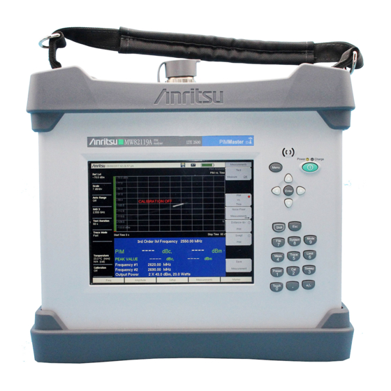
- Page 1 Anritsu MW82119A Manual Get Pricing & Availability at ApexWaves.com Call Today: 1-800-915-6216 Email: sales@apexwaves.com https://www.apexwaves.com/analyzers/anritsu/pim-master/MW82119A...
- Page 2 Maintenance Manual PIM Master™ MW82119A Passive InterModulation Analyzer Anritsu Company Part Number: 10580-00286 490 Jarvis Drive Revision: D Morgan Hill, CA 95037-2809 Published: July 2015 Copyright 2015 Anritsu Company http://www.anritsu.com...
-
Page 8: Safety Symbols
Some or all of the following five symbols may or may not be used on all Anritsu equipment. In addition, there may be other labels attached to products that are not shown in the diagrams in this manual. - Page 9 These hazardous compounds present a risk of injury or loss due to exposure. Anritsu Company recommends removing the battery for long-term storage of the instrument and storing the battery in a leak-proof, plastic container.
-
Page 10: Table Of Contents
Anritsu Customer Service Centers ........ - Page 11 Table of Contents (Continued) Appendix A—Test Records Introduction ..............A-1 Reference PIM Measurement .
-
Page 12: Chapter 1-General Information
Chapter 1 — General Information The Anritsu PIM Master is capable of producing up to 40 Watts of RF power in the cellular communications bands. Users must take precautions to minimize exposure to these RF fields: Always terminate the output port of the test equipment into a load, a loaded line, or a line that •... -
Page 13: Product Description
1-2 Product Description Chapter 1 — General Information Product Description The MW82119A PIM Master model is a portable passive inter-modulation analyzer featuring precise performance for the APT (700 MHz), LTE (700 MHz), LTE (800 MHz), Cellular (850 MHz), E-GSM (900 MHz), DCS (1800 MHz), PCS (1900 MHz), AWS (1700/2100 MHz), UMTS (2100 MHz), and LTE (2600 MHz) frequency bands. -
Page 14: Other Options
GPS Receiver (Requires GPS antenna sold separately) Optional Accessories For a complete list of the available accessories, refer to the PIM Master MW82119A Product Brochure & Technical Data Sheet (Anritsu part number 11410-00679). You can download a PDF copy of this document at the following URL: http://www.anritsu.com/en-US/Downloads/Brochures-Datasheets-and-Catalogs/Brochure/DWL9842.aspx... -
Page 15: Recommended Test Equipment
Table 1-3. Recommended Equipment Critical Specification Manufacturer/Model Synthesized Signal Frequency: 600 MHz to 3 GHz, Anritsu Model MG3691C with Generator Power Output: 0 dBm option 4 or option 5 Power Meter Power Range: –70 to +20 dBm Anritsu Model ML2438A... - Page 16 Chapter 1 — General Information 1-6 Replaceable Parts and Assemblies Part Number Description ND80833 MW82119A with Option 192 Filter Assembly ND75351 MW82119A with Option 192 RF Module Assembly ND80842 MW82119A with Option 193 Filter Assembly ND80400 MW82119A with Option 193 RF Module Assembly ND80841 MW82119A with Option 210 Filter Assembly ND80198...
- Page 17 1-6 Replaceable Parts and Assemblies Chapter 1 — General Information Part Number Description 3-72493-3 MW82119A-0850, 850 MHz Model Label 3-72493-4 MW82119A-0900, 900 MHz Model Label 3-72493-10 MW82119A-0800, 800 MHz Model Label 3-72493-7 MW82119A-0210, 2100 MHz Model Label 3-72493-8 MW82119A-0260, 2600 MHz Model Label PN: 10580-00286 Rev.
-
Page 18: Chapter 2-Pim Analyzer Verification
Chapter 2 — PIM Analyzer Verification The Anritsu PIM Master is capable of producing up to 40 Watts of RF power in the cellular communications bands. Users must take precautions to minimize exposure to these RF fields: Always terminate the output port of the test equipment into a load, a loaded line, or a line that •... -
Page 19: Reference Pim Measurement
The following test is used to verify the PIM measurement functionality. A known PIM reference (standard) is used for verification. Equipment Required • Anritsu Model 2000-1724-R or 2000-1749-R Low PIM Load (Termination) • Anritsu Model 1091-390-R or Anritsu Model 1091-403-R PIM Standard Procedure 1. - Page 20 Chapter 2 — PIM Analyzer Verification 2-2 Reference PIM Measurement PIM Standard Results Table 2-1. PIM Standard MW82119A with Carrier Frequencies IM3 Freq Result Expected F1: 734 MHz F2: 757 MHz 711 MHz –81 dBm ± 3 dB 1091-403-R (910 MHz) Option 700(L) F1: 734 MHz F2: 757 MHz 780 MHz...
-
Page 21: Output Power
Test Component, which consists of the Fixed Attenuator, and Test Cable. Component Characterization Equipment Required • Anritsu Model MG3691C Signal Generator with Option 4 or Option 5, or equivalent • Anritsu Model 34RKNF50 K(m) to N(f) Adapter • Power Meter, Anritsu Model ML2438A •... - Page 22 Chapter 2 — PIM Analyzer Verification 2-3 Output Power PIM Master Tx Frequency Table Table 2-2. MW82119A PIM Master F1 Carrier Frequencies F2 Carrier Frequencies F2: 756 MHz F1: 734 MHz Option 700 F2: 766 MHz F1: 734.5 MHz Option 700 F2: 788 MHz F1: 768 MHz Option 702...
-
Page 23: Output Power Verification
• Anritsu Model MS2712E Spectrum Analyzer or equivalent • Test Component from above consisting of: • Anritsu Model 3-1010-123 30 dB 50 W Fixed Attenuator • Anritsu Model 15NN50-1.5C RF Coaxial Cable • Anritsu Model 1091-423-R 7/16 DIN(m) to N(m) Adapter Procedure Follow this entire procedure for each instrument that you test. -
Page 24: Output Tone Power Accuracy
Chapter 2 — PIM Analyzer Verification 2-3 Output Power 11. Press the Shift key and then the Preset (1) key. Press the Preset submenu key to set the PIM Master to the factory preset state. 12. Confirm that all of the connectors are clean because any debris or contamination may cause incorrect measurement results. -
Page 25: Residual Pim Measurement
The following test is used to verify the residual PIM of the PIM Master. The procedure measures the internal residual PIM of the PIM Master. Equipment Required • Anritsu Model 2000-1724-R or 2000-1749-R Low PIM Load (Termination) • Anritsu Model 1091-390-R or Anritsu Model 1091-403-R PIM Standard Procedure Follow this entire procedure for each instrument that you test. -
Page 26: Option 31, Gps Verification
• Amphenol Model B1004A1-ND3G-93R-0.05-1W GPS Terminator or equivalent Procedure 1. Connect the external power supply (Anritsu PN 40-187-R) to the PIM Master. 2. Press the On/Off key to turn on the PIM Master. 3. Set the MW82119A to PIM Analyzer mode and preset the instrument. - Page 27 2-5 Option 31, GPS Verification Chapter 2 — PIM Analyzer Verification 2-10 PN: 10580-00286 Rev. D MW82119A MM...
-
Page 28: Chapter 3-Troubleshooting
Chapter 3 — Troubleshooting The Anritsu PIM Master is capable of producing up to 40 Watts of RF power in the cellular communications bands. Users must take precautions to minimize exposure to these RF fields: Always terminate the output port of the test equipment into a load, a loaded line, or a line that •... -
Page 29: Pim Analyzer Warning Messages
7. Receiver Amplitude Low This message can occur if signal amplitude degrades within the instrument. It can have an impact on overall measurement accuracy and should be an indicator to sent the unit to Anritsu Service Center for repair. PN: 10580-00286 Rev. D... -
Page 30: Operating Problems
The Main PCB Assembly has failed. One of the internal power rails may have failed. Contact your Anritsu Service Center. The PIM Master instrument Application Self Test – PIM Application Self Test fails: The RF PCB Assembly has failed. One of the internal power rails may have failed. Contact your Anritsu Service Center. Error Messages 1. - Page 31 3-5 Other Problems Chapter 3 — Troubleshooting 4. If you are in the middle of making measurements and absolutely cannot wait to replace the touch screen, then an emergency arrow mode navigation alternative is available. Select Touch Screen Calibration from the System menu and enter 1, and then enter 1 again.
-
Page 32: Chapter 4-Battery Information
Anritsu Company recommends removing the battery for long-term storage of the instrument and also recommends storing the battery in a leak-proof, plastic container. The following information relates to the care and handling of the Anritsu battery pack and Lithium-Ion batteries. -
Page 33: Battery Pack Removal And Replacement
4-2 Battery Pack Removal and Replacement Chapter 4 — Battery Information Battery Pack Removal and Replacement This section provides instructions for the removal and replacement of the PIM Master battery pack. Many of the procedures in this section are generic, and apply to many similar instruments. Photos Note and illustrations used here are representative and may show instruments other than the PIM Master. - Page 34 Chapter 4 — Battery Information 4-2 Battery Pack Removal and Replacement 3. Remove the battery access door by sliding it out of the slot in the case, as shown Figure 4-3. Removing the Battery Access Door Figure 4-3. MW82119A MM PN: 10580-00286 Rev.
- Page 35 4-2 Battery Pack Removal and Replacement Chapter 4 — Battery Information 4. With the battery access door completely removed, the battery snaps in and out of the compartment door, as illustrated in Figure 4-4. Note the battery orientation image in the cover. Removing the Battery Figure 4-4.
-
Page 36: Chapter 5-Assembly Replacement
Replacement of the Main PCB, RF Module, or Filter Assembly within the Chassis requires a full characterization with adjustments to be performed. Adjustments are not documented in this Maintenance Manual. Contact your local Anritsu Service Center for this service. Many of the procedures in this section are generic, and apply to many similar instruments. Photos Note and illustrations used are representative and may show instruments other than the PIM Master. -
Page 37: Front Panel Removal
5-3 Front Panel Removal Chapter 5 — Assembly Replacement Front Panel Removal Electrostatic Discharge (ESD) can damage the highly sensitive circuits in the instrument. The PIM Master contains components that can easily be damaged by electrostatic discharge (ESD). An ESD safe work area and proper ESD handling procedures that conform to ANSI/ESD S20.20-1999 or ANSI/ESD S20.20-2007 are mandatory to avoid ESD damage when handling Caution subassemblies or components found in the instrument. - Page 38 Chapter 5 — Assembly Replacement 5-3 Front Panel Removal 3. Remove the bottom bumper (Figure 5-2). The bottom bumper part number is 3-72497. Remove the Bottom Bumper Figure 5-2. 4. Remove the 2 screws retaining the Handle Strap (Figure 5-3). The Handle Strap part number is 2000-1713-R.
- Page 39 5-3 Front Panel Removal Chapter 5 — Assembly Replacement 5. Remove the Top Bumper and Handle Hand Strap (Figure 5-4). The top bumper part number is 3-72496. Remove the Top Bumper Figure 5-4. PN: 10580-00286 Rev. D MW82119A MM...
- Page 40 Chapter 5 — Assembly Replacement 5-3 Front Panel Removal 6. Remove the 8 screws retaining the Front Panel. a. Remove the 2 screws on the top (Figure 5-5) under the stickers. Remove the Top Screws Figure 5-5. b. Remove the 2 screws on the bottom (under the stickers), the 2 screws on the right side, and the 2 screws on the left side (Figure 5-6).
- Page 41 5-3 Front Panel Removal Chapter 5 — Assembly Replacement 7. Carefully raise the bottom edge of the front panel and unpeel the Kapton tape on the LCD cable connector (left side under the Front Panel). Remove the connector (Figure 5-7). LCD Cable Connector Figure 5-7.
-
Page 42: Tilt Bail
Chapter 5 — Assembly Replacement 5-3 Front Panel Removal 9. The Front Panel Assembly is now separated from the PIM Master body (Figure 5-9). Top and Bottom of the Front Panel Assembly Figure 5-9. 10. Reverse the above steps to reassemble the case. New screws with patch lock must be used for reassembly. -
Page 43: Front Panel Assemblies
5-4 Front Panel Assemblies Chapter 5 — Assembly Replacement Front Panel Assemblies These procedures allow access to the following replaceable parts and assemblies: • 3-15-165 — LCD Display with LED Backlight • ND80480 — 8.4 in GFG Touch Screen • 3-74999-3 — Main Numeric Keypad PCB •... - Page 44 Chapter 5 — Assembly Replacement 5-4 Front Panel Assemblies 3. Disconnect the LCD Backlight Cable from the Keypad PCB (Figure 5-11). Figure 5-11. Disconnect Backlight Cable 4. Carefully lift up and remove the bracket with the LCD attached (Figure 5-12). Figure 5-12.
- Page 45 5-4 Front Panel Assemblies Chapter 5 — Assembly Replacement 5. The GFG Touchscreen is connected to the Keypad PCB with a flexi-circuit. Pull down on the side of the connector to release the flexi-circuit and then gently pull the flexi-circuit straight out(Figure 5-13).
- Page 46 Chapter 5 — Assembly Replacement 5-4 Front Panel Assemblies 7. Carefully disconnect the Speaker connector and remove the 8 screws holding the Keypad PCB to the Front Panel Assembly (Figure 5-15). Figure 5-15. Remove Keypad PCB Screws 8. Carefully remove the PCB to expose the PCB membrane (Figure 5-16).
- Page 47 5-4 Front Panel Assemblies Chapter 5 — Assembly Replacement 9. Peal up the rubber keypad membrane (Figure 5-17). Figure 5-17. Remove Rubber Keypad Membrane 10. Carefully pry up the speaker with a stub nosed pick. Note that the front side of the speaker has a gasket (Figure 5-18).
- Page 48 Chapter 5 — Assembly Replacement 5-4 Front Panel Assemblies 11. Remove the 4 screws holding the LCD Display to the bracket (Figure 5-19). Figure 5-19. Replace LCD 12. Reverse the above steps to reassemble the Front Panel Assembly. 13. Note the correct cable path shown below when reattaching the LCD bracket to the Front Panel (Figure 5-20).
- Page 49 5-4 Front Panel Assemblies Chapter 5 — Assembly Replacement 14. Reverse the above steps to reassemble the front panel assembly. New screws with patch lock must be used for reassembly. Note 5-14 PN: 10580-00286 Rev. D MW82119A MM...
-
Page 50: Chassis Assemblies
Replacement of the Main PCB, RF Module or Filter Assembly requires a full characterization with Note adjustments to be performed. Adjustments are not documented in this Maintenance Manual. Contact your local Anritsu Service Center for this service. 1. Perform procedure in “Front Panel Removal” on page 5-2. - Page 51 5-5 Chassis Assemblies Chapter 5 — Assembly Replacement 2. Raise the connector side panel cover door and remove the 2 screws. Remove the door and attached base plate (Figure 5-21). Figure 5-21. Remove Door Panel 3. Remove the 6 screws from each side panel (Figure 5-22).
- Page 52 Chapter 5 — Assembly Replacement 5-5 Chassis Assemblies 5. Remove the 4 screws holding the bottom panel (Figure 5-23). Figure 5-23. Remove Bottom Panel Screws 6. Lower the bottom panel and disconnect the battery cable (Figure 5-24). Remove Connector Figure 5-24. Remove Bottom Panel MW82119A MM PN: 10580-00286 Rev.
- Page 53 5-5 Chassis Assemblies Chapter 5 — Assembly Replacement 7. Remove the 4 screws holding the top panel cover (Figure 5-25). Figure 5-25. Remove Top Panel Screws 5-18 PN: 10580-00286 Rev. D MW82119A MM...
- Page 54 Chapter 5 — Assembly Replacement 5-5 Chassis Assemblies 8. Slide the chassis out of the housing (Figure 5-26). Figure 5-26. Slide Chassis Out of Housing The design and size of the filter and RF assemblies vary based on the Option number of the MW82119A.
- Page 55 5-5 Chassis Assemblies Chapter 5 — Assembly Replacement Figure 5-28. GPS Module with MMCX Cable attached Figure 5-29. GPS SMA Connection on connector panel (inside and outside view) 5-20 PN: 10580-00286 Rev. D MW82119A MM...
- Page 56 Chapter 5 — Assembly Replacement 5-5 Chassis Assemblies 10. Remove the Emergency Stop cable assembly from the Main Board assembly. Remove the screws from the top plate of the filter assembly. Between 5 and 11 screws may be used based upon the model Option (Figure 5-30).
- Page 57 5-5 Chassis Assemblies Chapter 5 — Assembly Replacement 11. If applicable, remove the brackets from both sides of the filter assembly (Figure 5-31). The sample below has 4 screws on each side. On the connector panel side, slide the side bracket past the large black capacitor.
- Page 58 Chapter 5 — Assembly Replacement 5-5 Chassis Assemblies 12. Remove the five M3 x 6 screws on the perimeter (shown in Green) holding the motherboard to the chassis and the four M3 x 35 mm screws (shown in Red) holding the motherboard to the RF assembly (Figure 5-32).
- Page 59 14. If replacing the filter, then flip the assembly over so that it is resting on the Main PCB board shield. Carefully disconnect the 5 semi-rigid RF cables that are connected to the filter assembly by using the Anritsu 5/16 in torque wrench (p/n 01-201). Figure 5-35 illustrates the 5 cables.
- Page 60 Chapter 5 — Assembly Replacement 5-5 Chassis Assemblies 15. The filter assembly can now be removed (Figure 5-36). Figure 5-36. Remove Filter Assembly MW82119A MM PN: 10580-00286 Rev. D 5-25...
- Page 61 5-5 Chassis Assemblies Chapter 5 — Assembly Replacement 16. Note the cable routing, and then carefully remove the cover plate by sliding around the semi-rigid cables (Figure 5-37). Be careful to avoid damaging or bending the semi-rigid cables when removing the plate. Figure 5-37.
-
Page 62: A-1 Introduction
Continuing to document this process with each performance verification session provides a detailed history of the instrument performance. The Anritsu PIM Master is capable of producing up to 40 Watts of RF power in the cellular communications bands. Users must take precautions to minimize exposure to these RF fields: Always terminate the output port of the test equipment into a load, a loaded line, or a line that •... -
Page 63: A-2 Reference Pim Measurement
A-2 Reference PIM Measurement Appendix A — Test Records MW82119A Firmware Rev: _____________ Operator: ____________________ Date: _____________ Serial Number: _______________ Options: ___________________________________________________ Reference PIM Measurement Table A-1. Reference PIM Measurement with PIM Standard PIM Master Expected Values from MW82119A IM3 Frequency Table 2-1 on page 2-3 Measurement Reading Option ______... - Page 64 Appendix A — Test Records A-3 Output Power MW82119A Firmware Rev: _____________ Operator: ____________________ Date: _____________ Serial Number: _______________ Options: ___________________________________________________ Output Power (continued) Output Tone Power Accuracy Table A-4. PIM Output Tone Power Accuracy (1 of 2) PIM Master Expected Power Reading MW82119A Tone Frequency and Power...
-
Page 65: A-4 Residual Pim Measurement
A-4 Residual PIM Measurement Appendix A — Test Records MW82119A Firmware Rev: _____________ Operator: ____________________ Date: _____________ Serial Number: _______________ Options: ___________________________________________________ Table A-4. PIM Output Tone Power Accuracy (2 of 2) PIM Master Expected Power Reading MW82119A Tone Frequency and Power and Tolerance Measured Value F1 Carrier... - Page 66 ....2-4 Anritsu document part numbers ... . . 1-3 assemblies, factory only repairs ....1-4 parts, factory only repairs .
- Page 67 U to W turn-on problems ......3-1 verification tests frequency accuracy ..... .2-4 Unit Cannot Complete Boot-Up .
- Page 69 Anritsu Company 490 Jarvis Drive Anritsu utilizes recycled paper and environmentally conscious inks and toner. Morgan Hill, CA 95037-2809 http://www.anritsu.com...
Need help?
Do you have a question about the PIM Master MW82119A and is the answer not in the manual?
Questions and answers