Table of Contents
Advertisement
Quick Links
A l l t e s t I n s t r u me n t s , I n c .
5 0 0 C e n t r a l A v e .
F a r mi n g d a l e , N J 0 7 7 2 7
P : ( 7 3 2 ) 9 1 9 - 3 3 3 9
F : ( 7 3 2 ) 9 1 9 - 3 3 3 2
a l l t e s t . n e t
s s a l e s @ a l l t e s t . n e t
T h e t e s t & me a s u r e me n t
e q u i p me n t y o u n e e d a t
t h e p r i c e y o u w a n t .
A l l t e s t c a r r i e s t h e w o r l d ' s l a r g e s t s e l e c t i o n o f
u s e d / r e f u r b i s h e d b e n c h t o p t e s t & me a s u r e me n t
e q u i p me n t a t 5 0 % t h e p r i c e o f n e w .
O O u r e q u i p me n t i s g u a r a n t e e d w o r k i n g , w a r r a n t i e d , a n d
a v a i l a b l e w i t h c e r t i f i e d c a l i b r a t i o n f r o m o u r i n - h o u s e s t a f f
o f t e c h n i c i a n s a n d e n g i n e e r s .
• 1 0 + f u l l t i me t e c h n i c i a n s w i t h o v e r 1 5 0 y e a r s o f
s p e c i a l i z a t i o n
• 9 0 d a y w a r r a n t y & 5 d a y r i g h t o f r e t u r n o n a l l
e q u i p me n t
• • 1 - 3 y e a r w a r r a n t i e s f o r n e w a n d
p r e mi u m- r e f u r b i s h e d e q u i p me n t
• E v e r y u n i t t e s t e d t o O E M s p e c i f i c a t i o n s
• S a t i s f a c t i o n g u a r a n t e e d
Y o u h a v e p l a n s , w e w i l l h e l p y o u a c h i e v e t h e m.
A n y p r o j e c t . A n y b u d g e t .
t
G e t a q u o t e t o d a y !
C C a l l ( 7 3 2 ) 9 1 9 - 3 3 3 9 o r e ma i l s a l e s @a l l t e s t . n e t .
Advertisement
Table of Contents

Related Manuals for Anritsu PIM Master MW8219A


Summary of Contents for Anritsu PIM Master MW8219A
- Page 1 T h e t e s t & me a s u r e me n t e q u i p me n t y o u n e e d a t t h e p r i c e y o u w a n t . A l l t e s t I n s t r u me n t s , I n c .
- Page 2 User Guide PIM Master™ Passive Intermodulation Analyzer MW8219A, 1930 MHz – 1990 MHz, 2110 MHz – 2155 MHz MW8209A, 925 MHz – 960 MHz MW8208A, 869 MHz – 894 MHz...
- Page 4 MW8219A, 1930 MHz – 1990 MHz and 2110 MHz – 2155 MHz MW8209A, 925 MHz – 960 MHz MW8208A, 869 MHz – 894 MHz Anritsu Company Part Number: 10580-00280 490 Jarvis Drive Revision: F Morgan Hill, CA 95037-2809 Published: January 2012 Copyright 2012 Anritsu Company http://www.anritsu.com...
- Page 6 LIMITATION OF WARRANTY The foregoing warranty does not apply to Anritsu connectors that have failed due to normal wear. Also, the warranty does not apply to defects resulting from improper or inadequate maintenance by the Buyer, unauthorized modification or misuse, or operation outside of the environmental specifications of the product.
- Page 8 This product and its manuals may require an Export License or approval by the government of the product country of origin for re-export from your country. Before you export this product or any of its manuals, please contact Anritsu Company to confirm whether or not these items are export-controlled.
- Page 10 Some or all of the following five symbols may or may not be used on all Anritsu equipment. In addition, there may be other labels attached to products that are not shown in the diagrams in this manual.
- Page 11 For Safety Warning Always refer to the operation manual when working near locations at which the alert mark, shown on the left, is attached. If the operation, etc., is performed without heeding the advice in the operation manual, there is a risk of personal injury. In addition, the equipment performance may be reduced.
-
Page 12: Table Of Contents
......1-11 1-16 Anritsu Handheld Instruments ....... . . 1-11 1-17 Anritsu Line Sweep Tools (LST) . - Page 13 Table of Contents (Continued) 2-10 PIM Measurements Menu ........2-18 2-11 Marker Menu .
- Page 14 Table of Contents (Continued) Chapter Overview ..........4-2 Remote Access Password Protection .
- Page 15 Table of Contents (Continued) Contents-4 PN: 10580-00280 Rev. F MW8219A, MW8209A, MW8208A UG...
-
Page 16: Chapter 1-General Information
Chapter 1 — General Information The Anritsu PIM Master is capable of producing up to 100 Watts of RF power in the cellular communications bands. Users must take precautions to minimize exposure to these RF fields: Always terminate the output port of the test equipment into a load, a loaded line, or a line that will radiate or absorb the energy before beginning a PIM test. -
Page 17: Scope Of The Pim Master User Guide
PIM Analyzer and Distance-to-PIM Analyzer modes that are associated with supported Anritsu handheld instruments. This chapter provides a general overview of PIM analysis and the Anritsu PIM Master. It also includes instructions on care and user maintenance, describes frequency range pairs, illustrates a typical PIM analysis setup, and reviews updating the PIM Master firmware. -
Page 18: Additional Documentation
Passive Inter-Modulation (PIM) Analyzer. PIM Master Models Table 1-1 lists the current available models. Refer to the Anritsu web site for the latest information on available PIM Master models and frequency ranges. PIM Master Models Table 1-1. - Page 19 1-5 PIM Master Models Chapter 1 — General Information 1. For AWS, F1 will be in the PCS frequency range, and F2 will be in the AWS range. Passive Device goes Non-linear, Intermodulates the Two Frequencies, Generates PIM Product in Rx band, Raises Noise Floor.
-
Page 20: Standard Accessories
Chapter 1 — General Information 1-6 Standard Accessories Standard Accessories The Anritsu PIM Master includes a one year warranty which includes: hardware, firmware, and a Document of Calibration and Conformance. The following items are supplied with the product. Standard Accessories for PIM Master Models Table 1-2. -
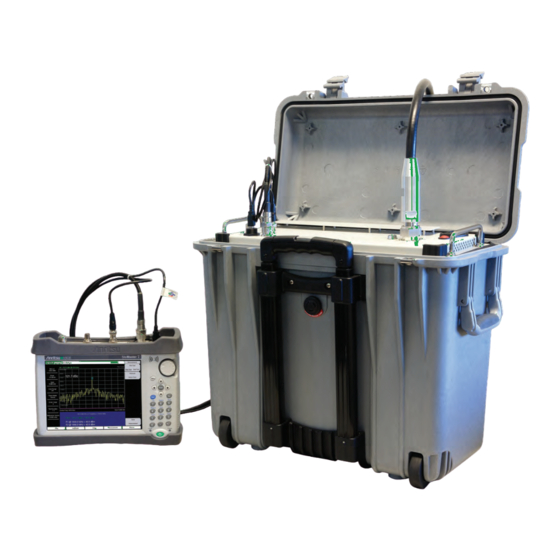
Page 21: Connection Diagram
Chapter 1 — General Information Connection Diagram The PIM Master is shipped with an Anritsu Interconnect Cable Assembly (part number: 2000-1635-R). The assembly includes the 3 cables that are needed to connect the PIM Master to a PIM Compatible Anritsu handheld instrument. -
Page 22: Pim Analysis Display Overviews
Chapter 1 — General Information 1-9 PIM Analysis Display Overviews PIM Analysis Display Overviews Figure 1-3 Figure 1-4 show typical PIM and Distance-to-PIM measurements with descriptive labels to help you become familiar with display screen (sweep window) elements. PIM Analyzer Battery Measurement Mode (PIM Analyzer) -
Page 23: Dtp Pim Analyzer
Refer to the PIM Master Product Brochure (part number: 11410-00546) for general specifications, detailed measurement specifications, ordering information, and available accessories. The product brochure is included with the instrument and is available on the Anritsu web site: http://www.anritsu.com. PN: 10580-00280 Rev. F MW8219A, MW8209A, MW8208A UG... -
Page 24: Preventive Maintenance
1. Connect the PIM Master to the Anritsu handheld instrument as shown in Section 1-8 “Connection Diagram” on page 1-6. 2. For PIM Analysis, set the PIM Master (via the Anritsu handheld instrument) as follows: Residual PIM Test Settings Table 1-3. -
Page 25: Esd Caution
PIM Master must be returned to an authorized service center annually for calibration. If your PIM Master does not show similar results, contact Anritsu customer service at: http://www.anritsu.com/Contact.asp Anritsu recommends an annual calibration and performance verification of the Note PIM Master. -
Page 26: Supply Voltage And Replacing A Fuse
Figure 3-1). 1-17 Anritsu Line Sweep Tools (LST) Anritsu Line Sweep Tools can download and open PIM files and DTP files. LST provides a means of reviewing and analyzing traces on a PC. MW8219A, MW8209A, MW8208A UG PN: 10580-00280 Rev. F... -
Page 27: Pim Master Firmware Update
Anritsu at +1-800-ANRITSU (+1-800-267-4878). To determine the current firmware version of your PIM Master, use the following procedure on your Anritsu Handheld instrument, which must be connected to the PIM Master (refer to Figure 1-2, “PIM Master Connection Diagram” on page 1-6): 1. -
Page 28: Secure Environment Workplace
Chapter 1 — General Information 1-19 Secure Environment Workplace 1-19 Secure Environment Workplace Refer to the Anritsu handheld instrument User Guide. For USB storage, Anritsu recommends part number 2000-1520-R USB Flash Note Drive. MW8219A, MW8209A, MW8208A UG PN: 10580-00280 Rev. F... - Page 29 1-19 Secure Environment Workplace Chapter 1 — General Information 1-14 PN: 10580-00280 Rev. F MW8219A, MW8209A, MW8208A UG...
-
Page 30: Chapter 2-Pim Analyzer
Chapter 2 — PIM Analyzer The Anritsu PIM Master is capable of producing up to 100 Watts of RF power in the cellular communications bands. Users must take precautions to minimize exposure to these RF fields: Always terminate the output port of the test equipment into a load, a loaded line, or a line that will radiate or absorb the energy before beginning a PIM test. -
Page 31: Connection Panel Overview
5. Connection Diagram 6. USB Type-B Connection (connect to Anritsu handheld instrument) 7. 10 MHz Reference Output Signal, BNC (female) (connect to Anritsu handheld instrument) 8. RF Out Connector, N Type (female) (connect to the Spectrum Analyzer RF In connector of your Anritsu handheld instrument) 9. -
Page 32: Pim Master Connection To Handheld Instrument
2-2 Connection Panel Overview PIM Master Connection to Handheld Instrument When an Anritsu handheld instrument is operating in PIM Analyzer mode, the instrument attempts to connect through the USB connection to the PIM Master. If you want to work in PIM Analyzer mode without connecting to the PIM Master, then you can press Shift + 5 on the handheld instrument to disable USB communications. -
Page 33: Pim Analysis Setup
2-3 PIM Analysis Setup Chapter 2 — PIM Analyzer PIM Analysis Setup Before turning on power on the PIM Master or on the connected Anritsu handheld instrument, connect the cables between the instruments and the DUT as shown in the diagram in Figure 1-2. -
Page 34: Configure The Pim Test
2-3 PIM Analysis Setup 5. Power on the PIM Master. 6. Power on the handheld instrument and select the PIM Analyzer mode. Refer to the Anritsu handheld instrument User Guide for additional information on selecting the PIM Analyzer mode. Configure the PIM Test Frequency Setup 1. - Page 35 2-3 PIM Analysis Setup Chapter 2 — PIM Analyzer The intermodulation distortion (IMx) is a mathematical function of F1 and F2. 3rd Order Intermodulation (IM3) = 2F1–F2 or 2F2–F1 5th Order Intermodulation (IM5) = 3F1–2F2 or 3F2–2F1 7th Order Intermodulation (IM7) = 4F1–3F2 or 4F2–3F1 Finding IM3 when F1 = 1930 MHz and F2 = 1990 MHz: IM3 = 2F1–F2 = 1870 MHz...
- Page 36 Chapter 2 — PIM Analyzer 2-3 PIM Analysis Setup 4. Press the Intermod Order submenu key so that the desired inter-modulation frequency order to be viewed is underlined. 3rd order is the most commonly chosen measurement. 5. Use the Span setting to set the frequency width in the display. Press the Span submenu key.
- Page 37 2-3 PIM Analysis Setup Chapter 2 — PIM Analyzer Spectral Trace View Figure 2-5. Bar Graph View Figure 2-6. PN: 10580-00280 Rev. F MW8219A, MW8209A, MW8208A UG...
- Page 38 Chapter 2 — PIM Analyzer 2-3 PIM Analysis Setup Parameter Setup Dialog Box The Parameter Setup submenu (under the Freq main menu or Setup main menu) opens the Frequency Configuration dialog box (Figure 2-7). This dialog box displays the current carrier frequencies, power, and intermodulations.
- Page 39 2-3 PIM Analysis Setup Chapter 2 — PIM Analyzer Parameter Setup Display for Touch Screen Instruments Figure 2-8. 2-10 PN: 10580-00280 Rev. F MW8219A, MW8209A, MW8208A UG...
-
Page 40: Making The Pim Measurement
PIM Master Test Port to the DUT. PIM distortion is returned through the PIM Master to the Anritsu handheld instrument. The results are displayed on screen in either spectrum view or bar graph. The RF-On light on the PIM Master front panel illuminates during the PIM test. - Page 41 3. Save the current measurement by pressing the Save Measurement submenu key. The Save dialog box opens. 4. Type a name for the measurement to be saved and press Enter. Refer to the Anritsu handheld instrument User Guide for additional information.
-
Page 42: Menu Map
Chapter 2 — PIM Analyzer 2-5 Menu Map Menu Map Figure 2-11 shows the map of the PIM Analyzer mode menus. The following sections describe main menus and associated submenus. Refer to your instrument Spectrum Analyzer Measurement Guide for additional information on the screen display and Spectrum Analyzer measurements. - Page 43 2-5 Menu Map Chapter 2 — PIM Analyzer Frequency Amplitude Setup Measurements Marker Carrier F1 Reference Level Output Power Test Marker 1.930 GHz -50.0 dBm 20 W 1 2 3 4 5 6 Carrier F2 Scale Test Duration 1.990 GHz 10 dB/div 20 s Intermod Order...
-
Page 44: Frequency (Freq) Menu
Span Intermod Order: Select the 3rd, 5th or 7th order of intermodulation. The Anritsu handheld will automatically set the center frequency based on the 5.000 kHz new intermod. Span: Press the Freq main menu key followed by the Span submenu key and enter the desired span. -
Page 45: Amplitude Menu
2-7 Amplitude Menu Chapter 2 — PIM Analyzer Amplitude Menu Key Sequence: Amplitude Reference Level: The reference level is the top graticule line on the display, and can be set from +30 dBm to –150 dBm. A value may be entered from the Amplitude keypad, use the ±... -
Page 46: Setup Menu
Chapter 2 — PIM Analyzer 2-8 Setup Menu Setup Menu Key Sequence: Setup Setup Output Power: Press this submenu key to set the output power level for Output Power both carrier frequencies F1 and F2. Options are 20 W (43 dBm), 30 W (45 dBm), 40 W (46 dBm). -
Page 47: Measurements Menu
Measurement Figure 2-15. Measurements Menu If your Anritsu handheld instrument is in the Distance-to-PIM mode, then pressing PIM changes the Freq/Dist main menu key to Freq and displays the Frequency submenu keys accordingly. 2-10 PIM Measurements Menu Key Sequence: Measurements >... -
Page 48: Marker Menu
Chapter 2 — PIM Analyzer 2-11 Marker Menu 2-11 Marker Menu Key Sequence: Marker Press the Marker main menu key to open the Marker menu. The instrument is equipped with six markers. Any or all markers can be employed simultaneously. Marker Marker Marker: Press this submenu key to selects which marker (1, 2, 3, 4, 5, 6) is... - Page 49 2-14 Trace Menu Chapter 2 — PIM Analyzer 2-20 PN: 10580-00280 Rev. F MW8219A, MW8209A, MW8208A UG...
-
Page 50: Limit Menu
By using Save-On-Event (from Shift (7), for the File menu). a signal that exceeds a limit line can be automatically saved. Refer to your Anritsu handheld instrument User Guide for details. Limit... -
Page 51: Other Menus
2-16 Other Menus Chapter 2 — PIM Analyzer 2-16 Other Menus Preset, File, System, and Mode menus are described in your Anritsu handheld instrument User Guide. 2-22 PN: 10580-00280 Rev. F MW8219A, MW8209A, MW8208A UG... -
Page 52: Chapter 3-Distance-To-Pim™ (Dtp)
Distance-to-PIM™ (DTP) analyzer features are displayed in the relative menus. The choice between PIM analysis and Distance-to-PIM™ analysis is made in the Measurements menu. The Anritsu PIM Master is capable of producing up to 100 Watts of RF power in the cellular communications bands. Users must take precautions to minimize... -
Page 53: Chapter Overview
3-2 Chapter Overview Chapter 3 — Distance-to-PIM™ (DTP) Chapter Overview This chapter contains the following sections: • Section 3-3 “Connection Panel Overview” on page 3-2 • Section 3-4 “DTP Measurement” on page 3-2 • Section 3-5 “DTP Measurement Setup” on page 3-4 •... - Page 54 Chapter 3 — Distance-to-PIM™ (DTP) 3-4 DTP Measurement When any parameter is highlighted, keying in a value and pressing the Enter key or a menu key completes the setting, and the selection highlight is incremented downward in the list. You can also press the Esc key to abort these settings and return to the Freq/Dist menu or the Sweep/Setup menu, depending upon your starting point.
-
Page 55: Dtp Measurement Setup
Distance-to-PIM™ menus, refer to section “Menu Map” on page 3-8. Anritsu handheld instruments with a touch screen offer additional options for some features. You can touch a submenu key or a screen feature (such as the button for Note... - Page 56 Chapter 3 — Distance-to-PIM™ (DTP) 3-5 DTP Measurement Setup 5. In the DTP Parameters window, highlighting the Preset State button displays the Preset State menu. Press the Preset State List submenu key (or touch the Preset State button on the screen) to open a list box. Select from the list of preset states (with differing frequencies and output powers).
-
Page 57: Dtp Testing Calibration
13. Highlight (or touch) the Output Power button to open the Select PIM Output Power list box. Select an appropriate power level and press Enter. 14. Press the Continue button and, if the Anritsu handheld instrument is calibrated, then continue with Step 15. -
Page 58: Post-Calibration Measurement
Chapter 3 — Distance-to-PIM™ (DTP) 3-6 DTP Testing Calibration Post-Calibration Measurement A good practice is performing a DTP measurement after the calibration in order to verify that measurements appear normal after the calibration. Figure 3-2 represents a typical Distance-to-PIM post-calibration measurement. Typical DTP Measurement After a Calibration Figure 3-2. -
Page 59: Making A Dtp Measurement
4. Save the current measurement by pressing the Save Measurement submenu key. The Save Measurement dialog box opens. 5. Type a name for the measurement to be saved and press Enter. Refer to your Anritsu handheld instrument User Guide for additional information about file handling. - Page 60 Chapter 3 — Distance-to-PIM™ (DTP) 3-8 Menu Map Freq/Dist Amplitude Sweep/Setup Measurements Marker Output Power Test Marker Carrier F1 1.930 GHz 80.0 dB 20 W 1 2 3 4 5 6 Carrier F2 Start Test Duration Bottom 2.110 GHz 140.0 dB 10 s Carrier F2 Stop Distance-to-...
-
Page 61: Freq/Dist Menu
3-9 Freq/Dist Menu Chapter 3 — Distance-to-PIM™ (DTP) Freq/Dist Menu Key Sequence: Freq/Dist. Freq/Dist Carrier F1: Press the Freq/Dist main menu key followed by the Carrier F1 submenu key and enter the desired frequency using the keypad, the arrow Carrier F1 keys, or the rotary knob. -
Page 62: Dtp Aid Menu
Chapter 3 — Distance-to-PIM™ (DTP) 3-10 DTP Aid Menu 3-10 DTP Aid Menu Key Sequence: Freq/Dist > DTP Aid Key Sequence: Sweep/Setup > DTP Aid DTP Aid Units: Press this submenu key to display the Units menu. Units Start Start Calibration: Press this submenu key to initiate the calibration process. Calibration The calibration that is used for a DTP measurement is a normalized calibration using a –80 dBm PIM standard. -
Page 63: Dtp Setup Menu
3-11 DTP Setup Menu Chapter 3 — Distance-to-PIM™ (DTP) 3-11 DTP Setup Menu Key Sequence: Freq/Dist > More DTP Setup Cable Loss: Press this submenu key to enter the loss in dB/ft or dB/m for the selected cable by using the keypad, the arrow keys, or the rotary knob, and Cable Loss then press Enter. -
Page 64: Standard List Menu
Chapter 3 — Distance-to-PIM™ (DTP) 3-12 Standard List Menu 3-12 Standard List Menu Key Sequence: Freq/Dist > More > Cable Highlight Cable in the DTP Parameters window. The Cable List Box and the Standard List menu are displayed simultaneously Standard List Top of List: Press this submenu key to highlight the cable at the top of the list. -
Page 65: Windowing Menu
3-13 Windowing Menu Chapter 3 — Distance-to-PIM™ (DTP) 3-13 Windowing Menu For a description of these windowing features, refer to Appendix B, “Windowing”. Key Sequence: Freq/Dist > More > Window Windowing Rectangular: Press this submenu key to select Rectangular windowing. Rectangular Nominal Side Lobe: Press this submenu key to select Nominal Side Lobe Nominal Side Lobe... -
Page 66: Dtp Amplitude Menu
Chapter 3 — Distance-to-PIM™ (DTP) 3-14 DTP Amplitude Menu 3-14 DTP Amplitude Menu Key Sequence: Amplitude Amplitude Top: Press this submenu key to set the top amplitude value. 80.0 dB Bottom: Press this submenu key to set the bottom amplitude value. Bottom 140.0 dB Autoscale: Press this submenu key to adjust the Top and Bottom amplitude... -
Page 67: Sweep/Setup Menu
3-15 Sweep/Setup Menu Chapter 3 — Distance-to-PIM™ (DTP) 3-15 Sweep/Setup Menu Key Sequence: Sweep/Setup Sweep/Setup Output Power: Press this submenu key to set the output power level for both carrier frequencies, F1 and F2. Options are 20 W (43 dBm), 30 W Output Power (45 dBm), 40 W (46 dBm). -
Page 68: Measurements Menu
Measurement Figure 3-14. DTP Measurements Menu If your Anritsu handheld instrument is in the PIM mode, then pressing Distance-to-PIM changes the Frequency main menu key to Freq/Dist and displays the Freq/Dist submenu keys accordingly. MW8219A, MW8209A, MW8208A UG PN: 10580-00280 Rev. -
Page 69: Preset State Menu
3-18 Preset State Menu Chapter 3 — Distance-to-PIM™ (DTP) 3-18 Preset State Menu This menu is displayed when the Preset State button is highlighted in the DTP Parameters window (Figure 3-1 on page 3-4). Preset State List: Press this submenu key to open the Select DTP Preset State list box and select one of the following: Preset State Preset... -
Page 70: Cable Menu
Chapter 3 — Distance-to-PIM™ (DTP) 3-20 Cable Menu 3-20 Cable Menu This menu is displayed when the Cable button is highlighted in the DTP Parameters window (Figure 3-1 on page 3-4). Cable Cable List: Press this submenu key to display the Cable list box (refer to Figure 3-9 on page 3-13). - Page 71 3-21 Output Power Menu Chapter 3 — Distance-to-PIM™ (DTP) 3-20 PN: 10580-00280 Rev. F MW8219A, MW8209A, MW8208A UG...
-
Page 72: Chapter 4-Programming Commands
Chapter 4 — Programming Commands The Anritsu PIM Master is capable of producing up to 100 Watts of RF power in the cellular communications bands. Users must take precautions to minimize exposure to these RF fields: Always terminate the output port of the test equipment into a load, a loaded line or a line that will radiate or absorb the energy before beginning a PIM test. -
Page 73: Chapter Overview
When a password has been set, unauthorized remote access is prevented. In addition, only one user can be connected at any one time. Many Anritsu handheld instruments can accept a Remote Access Password. If a password has been set, then your remote access requires the password. Refer to your instrument user guide and programming manual for a description of this feature and for instructions to use it. -
Page 74: Calculate Subsystem
Chapter 4 — Programming Commands 4-4 :CALCulate Subsystem :CALCulate Subsystem The commands in this subsystem process data that has been collected via the SENSe subsystem. :CALCulate:DTPMeas:CABLoss :CALCulate:DTPMeas:CABLoss? Title: DTP cable loss Description: Sets and queries DTP cable loss in dB/current distance unit. Parameter: cable_loss_value Default Value: None –... - Page 75 4-4 :CALCulate Subsystem Chapter 4 — Programming Commands :CALCulate:DTPMeas:FRESolution? Title: DTP fault resolution Description: Queries DTP fault resolution in current distance unit. Parameter: None Default Value: None – Returns error Front Panel Access: Freq/Dist, DTP Aid, Fault Res :CALCulate:DTPMeas:PVELocity :CALCulate:DTPMeas:PVELocity? Title: DTP cable propagation velocity index Description: Sets and queries DTP cable propagation velocity index.
- Page 76 Chapter 4 — Programming Commands 4-4 :CALCulate Subsystem :CALCulate:DTPMeas:WINDow :CALCulate:DTPMeas:WINDow? Title: DTP Windowing Description: Sets and queries the type of windowing in order of increasing side lobe reduction. Windowing settings are: rectangular, nominal side lobe, low side lobe, and minimum side lobe. Parameter: RECTangular = Rectangular Windowing NSLobe = Nominal Side Lobe Windowing LSLobe = Low Side Lobe Windowing...
-
Page 77: Calibration Subsystem
:CALibration Subsystem The commands in this subsystem control the system calibration. :CALibration:DTPMeas:STATe :CALibration:DTPMeas:STATe? Title: Calibration State Description: Starts calibration and reports its state. The calibration that is used for a DTP measurement is a normalized calibration using a –80 dBm PIM standard Parameter: 0 = invalidate the current calibration 1 = perform calibration... -
Page 78: Initiate Subsystem
Chapter 4 — Programming Commands 4-7 :INITiate Subsystem :INITiate Subsystem The commands in this subsystem control the triggering of measurements. :INITiate:PIManalyzer:MEASure NOISe|PIM Title: Trigger PIM Analyzer Measurement Description: PIM triggers the sweep of the measurement receiver unit and turns on the RF PIM Analyzer unit so the measurement receiver can measure inter modulation distortion generated from the PIM Master and the system under test. -
Page 79: Sense Subsystem
4-8 :SENSe Subsystem Chapter 4 — Programming Commands :SENSe Subsystem The commands in this subsystem relate to device-specific parameters, not signal-oriented parameters. :[SENSe:]:DTPMeas:AVERage:TYPE :[SENSe:]:DTPMeas:AVERage:TYPE? Title: DTP Trace Mode Description: Sets and queries DTP trace mode Parameter: NONE = normal MAXimum = max trace hold Default Value: None –... - Page 80 Chapter 4 — Programming Commands 4-8 :SENSe Subsystem :[SENSe:]:DTPMeas:FREQuency:BANd :[SENSe:]:DTPMeas:FREQuency:BANd? Title: DTP Preset State Description: Sets and queries current DTP preset state. This sets up various parameters to some predetermined values. Parameter: Parameter Description PIM Master PCS_20W PCS band with 20 watts output power MW8219A PCS_40W PCS band with 40 watts output power MW8219A...
- Page 81 Chapter 4 — Programming Commands :[SENSe:]:DTPMeas:FREQuency:F1|F2:STARt|F2:STOP :[SENSe:]:DTPMeas:FREQuency:F1|F2:STARt|F2:STOP? Title: PIM Master Frequency Setup Description: Sets the PIM Master LO frequencies, calculates the IMx Order frequency, and sets the Anritsu handheld instrument for the corresponding IMx frequency. Parameter: MW8208A: 869 MHz to 894 MHz MW8209A:...
- Page 82 Chapter 4 — Programming Commands 4-8 :SENSe Subsystem :[SENSe:]:DTPMeas:MEASure :[SENSe:]:DTPMeas:MEASure? Title: DTP Measurement Description: Sets and queries DTP measurement Parameter: 0 = Stop measurement 1 = Start measurement Default Value: None – Returns error Example: To start DTP measurement: :SENSe:DTPMeas:MEASure 1 Front Panel Access: Measurements, Test :[SENSe:]:DTPMeas:OUTput:POWer...
- Page 83 :[SENSe:]PIManalyzer:AUTorange? Title: Auto Range Setup Description: Sets the Anritsu handheld instrument to auto range the amplitude of the PIM signal received from the PIM Master. There is an initial 1 second measurement of the PIM power so the Anritsu handheld instrument can adjust reference level and span appropriately.
- Page 84 4-8 :SENSe Subsystem :[SENSe:]PIManalyzer:FREQuency:F1|F2 :[SENSe:]PIManalyzer:FREQuency:F1|F2? Title: PIM Master Frequency Setup Description: Sets the PIM Master LO frequencies, calculates the IMx Order frequency and sets the Anritsu handheld instrument for the corresponding IMx frequency. Parameter: MW8208A: 869 MHz to 894 MHz MW8209A:...
- Page 85 4-8 :SENSe Subsystem Chapter 4 — Programming Commands :[SENSe:]PIManalyzer:IMD:ORDer :[SENSe:]PIManalyzer:IMD:ORDer? Title: Measurement Receiver / PIM Master Inter-Modulation Distortion (IMD) Order Setup Description: Sets the measurement receiver center frequency to receive one of the following IMDs from the PIM Master measurement system: 3/5/7. The query command returns the possible strings “3rd”, “5th”...
- Page 86 Chapter 4 — Programming Commands 4-8 :SENSe Subsystem :[SENSe:]PIManalyzer:MODe :[SENSe:]PIManalyzer:MODe? Title: PIM Analyzer Mode, Set or Request Description: Puts the system into either PIM measurement mode or Distance-to-PIM™ measurement mode. The query reports the current system mode. Parameter: None Query Response: PIM or DTP Default Value: None Example: To set the PIM Analyzer mode to measure Distance-to-PIM™: :SENSe:PIManalyzer:MODe DTP...
- Page 87 4-8 :SENSe Subsystem Chapter 4 — Programming Commands :[SENSe:]PIManalyzer:TESt:DURation :[SENSe:]PIManalyzer:TESt:DURation? Title: PIM Test Measurement Test Duration Description: Sets the amount of time in seconds the PIM Master will be on for intermodulation distortion measurements. Parameter: <time> Default Value: 20 Default Unit: Seconds Range: 1.0 to 60.0 seconds Example: To set the test duration time to 5 seconds: :SENSe:PIManalyzer:TESt:DURation 5.0...
-
Page 88: Appendix A-Instrument Messages And Errors
Appendix A — Instrument Messages and Errors Spectrum Analyzer Messages External Reference Messages Attempting to lock to External Reference When the instrument detects an external reference frequency has been connected, this message is displayed briefly. External Reference Locked Successfully When the instrument has detected an external reference and has successfully locked to the reference, this message is displayed briefly. -
Page 89: Pim Analyzer Messages
PIM Analyzer Messages External Reference Messages PIM External Reference Error The Anritsu handheld instrument can not lock onto the reference signal from the PIM Master and switches to its own internal frequency reference. Failures (Errors) Messages 48V PIM Power Supply Fail This power supply failure will cause signal dropout with no PIM measurement capability. -
Page 90: Appendix B-Windowing
Appendix B — Windowing Introduction The theoretical requirement for inverse FFT is for the data to extend from zero frequency to infinity. Side lobes appear around a discontinuity because the spectrum is cut off at a finite frequency. Windowing reduces the side lobes by smoothing out the sharp transitions at the beginning and at the end of the frequency sweep. -
Page 91: Rectangular Windowing
B-2 Distance-to-PIM Windowing Examples Appendix B — Windowing Rectangular Windowing Distance To PIM Return Loss (dB) Feet Figure B-1. Rectangular Windowing PN: 10580-00280 Rev. F MW8219A, MW8209A, MW8208A UG... -
Page 92: Nominal Side Lobe Windowing
Appendix B — Windowing B-2 Distance-to-PIM Windowing Examples Nominal Side Lobe Windowing Distance To PIM Return Loss (dB) Feet Figure B-2. Nominal Side Lobe Windowing MW8219A, MW8209A, MW8208A UG PN: 10580-00280 Rev. F... -
Page 93: Low Side Lobe Windowing
Low Side Lobe Windowing Distance To PIM Return Loss (dB) Feet Figure B-3. Low Side Lobe Windowing PN: 10580-00280 Rev. F MW8219A, MW8209A, MW8208A UG... -
Page 94: Minimum Side Lobe Windowing
Appendix B — Windowing B-2 Distance-to-PIM Windowing Examples Minimum Side Lobe Windowing Distance To PIM Return Loss (dB) Feet Figure B-4. Minimum Side Lobe Windowing MW8219A, MW8209A, MW8208A UG PN: 10580-00280 Rev. F... - Page 95 B-2 Distance-to-PIM Windowing Examples Appendix B — Windowing PN: 10580-00280 Rev. F MW8219A, MW8209A, MW8208A UG...
-
Page 96: Appendix C-Preset State Definitions
Appendix C — Preset State Definitions Introduction Preset state definitions are provided for convenience. The Select DTP Preset State list box is displayed by pressing the Preset State parameter button in the DTP Parameters window (refer to Figure 3-1 on page 3-4). -
Page 97: Preset States
C-3 Preset States Appendix C — Preset State Definitions Preset States Table C-1. MW8219A DTP Preset States PCS/AWS PCS/AWS Parameter PCS 1900 20W PCS 1900 40W 1900/2100 20W 1900/2100 40W Start Distance Stop Distance F1 Frequency 1930 1930 1930 1930 F2 Start 1950 1950... - Page 98 Appendix C — Preset State Definitions C-3 Preset States Table C-3. MW8208A DTP Preset States Parameter US Cellular 850 20W US Cellular 850 40W Start Distance Stop Distance F1 Frequency F2 Start Frequency F2 Stop Frequency 891.5 891.5 Data Points Cable None None...
- Page 99 C-3 Preset States Appendix C — Preset State Definitions PN: 10580-00280 Rev. F MW8219A, MW8209A, MW8208A UG...
-
Page 100: Index
....3-1 Anritsu Line Sweep Tools (LST) ..1-11 display screen features ..1-8 Application Self Test measurement setup . - Page 101 F to P example SCPI command menu, DTP analyzer initiate calibration ... . . 4-6 Amplitude ....3-15 query PIM Analyzer mode .
- Page 102 R to W analyzer menu map ... 2-13 Safety Symbols causes of PIM ....1-2 For Safety .
- Page 103 Index-4 PN: 10580-00280 Rev. F MW8219A, MW8209A, MW8208A UG...
- Page 105 Anritsu Company 490 Jarvis Drive Anritsu prints on recycled paper with vegetable soybean oil ink. Morgan Hill, CA 95037-2809 http://www.anritsu.com...
Need help?
Do you have a question about the PIM Master MW8219A and is the answer not in the manual?
Questions and answers