Sign In
Upload
Manuals
Brands
Novatel Manuals
Receiver
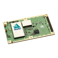
OEM7500
User Manuals: Novatel OEM7500 GNSS Receiver
Manuals and User Guides for Novatel OEM7500 GNSS Receiver. We have
2
Novatel OEM7500 GNSS Receiver manuals available for free PDF download: Installation And Operation Manual
Novatel OEM7500 Installation And Operation Manual (292 pages)
Brand:
Novatel
| Category:
Receiver
| Size: 10 MB
Table of Contents
Table of Contents
3
Proprietary Notice
2
Table of Contents
12
Notices Receiver Card
16
Ethernet Port
17
Customer Support
21
Contact Information
21
Chapter 1 OEM7 SPAN Overview
23
Fundamentals of GNSS+INS
23
Models and Features
24
INS Options
24
IMU Grade
25
Table 1: ins Options
25
Table 2: SPAN-Compatible Imus
25
Related Documents and Information
26
Chapter 2 SPAN Installation
27
OEM7 Receiver Card Installation
27
Selecting a GNSS Antenna
29
Choosing a Coaxial Cable
29
Mounting the GNSS Antenna
30
Mount the IMU
30
Connect the IMU to the OEM7 Receiver Card
32
Table 3: IMU Connection Method
33
Table 4: Receiver to ADIS-16488 Pin Connections
37
Table 5: Receiver to EG320N Pin Connections
39
Table 6: Receiver to STIM300 Pin Connections
41
Connect Power
44
Table 7: IMU Power Supply
44
MIC Installation
45
Install a MIC in a Stack up Configuration
45
Install a MIC in a Standalone Configuration
51
UIC Installation
56
Table 8: COM Port Recommendations
56
Mount the SPAN System Components
58
Connect the IMU to the UIC
59
Connect the UIC to a Receiver
59
Table 9: COM Port Recommendations
59
Connect Power to the UIC and OEM7 Receiver
60
UIC Status Leds
60
Table 10: UIC Status Leds
60
Pwrpak7 Installation
61
Connect the IMU to the Pwrpak7
63
Pwrpak7-E1 Installation
64
Table 11: Additional IMU to Pwrpak7 Connections
64
Wheel Sensor Installation
66
Wheel Sensor Requirements
66
Wheel Sensor Connection
67
Table 12: Kistler to Novatel Wheel Sensor Cable Connections
67
IMU Leds
69
Table 13: IMU-IGM Leds
70
Table 14: IMU Enclosure Leds
70
Chapter 3 SPAN Operation
71
Definition of Reference Frames Within SPAN
71
The Local-Level Frame (ENU)
71
The IMU Body Frame
72
The Vehicle Frame
72
The User Output Frame
73
SPAN Translations and Rotations
73
Translational Offsets
73
Rotational Offsets
75
Software Configuration
77
Minimum Recommended Configuration
77
GNSS Configuration
77
INS Profiles
77
Table 15: ins Profiles
78
SPAN Configuration
79
Table 16: Enable ins Commands
79
Real-Time Operation
82
Table 17: Inertial Solution Status
83
System Start-Up and Alignment Techniques
84
INS Seed / Fast ins Initialization
86
Navigation Mode
88
Data Collection
88
Table 18: NVM Seed Indication
88
Table 19: Solution Parameters
88
Lever Arm Calibration Routine
90
Body to Vehicle Frame Rotation Calibration Routine
91
Multi-Line Body to Vehicle Frame Rotation Calibration Routine
92
Synchronizing External Equipment
94
Configuring an Input Strobe
94
Adding Timed Sensor Triggers
95
Configuring the Hardware
95
Table 20: Valid Event Inputs and Outputs for Timed Sensor Triggers
95
Configuring the Software
96
Using Timed Event Pulses
96
Recording Incoming Sensor Events
96
SPAN Wheel Sensor Configuration
96
Wheel Sensor Data Collected on the Pwrpak7
97
Wheel Sensor Data Collected on IMU
98
Azimuth Sources on a SPAN System
98
Course over Ground
99
Inertial Azimuth
99
ALIGN Azimuth
99
Table 21: Logs with Azimuth Data
99
Data Collection for Post Processing
100
Firmware Updates and Model Upgrades
101
Variable Lever Arm
101
Reference Frame Description
101
How to Use Variable Lever Arm
103
Table 22: Logs Used with Variable Lever Arm
104
Table 23: Commands Used with Variable Lever Arm
104
Relative ins
105
Configure Relative ins
106
Chapter 4 SPAN with Dual Antenna
108
Installation
108
Configuring ALIGN with SPAN
110
Configuring SPAN with ALIGN
111
Alignment on a Moving Vessel - Aided Transfer Alignment
112
Alignment on a Stationary Vehicle - Aided Static Alignment
112
Unaided Alignment
112
Automatic Alignment Mode - Automatic Alignment (Default)
112
SPAN ALIGN Attitude Updates
113
APPENDIX A IMU Technical Specifications
114
HG1700 IMU (Single-Connector Enclosure)
115
Table 24: HG1700 IMU Physical Specifications
115
HG1700 IMU Mechanical Drawings
116
HG1700 IMU Performance
118
Table 25: HG1700-AG58 IMU Performance
118
Table 26: HG1700-AG62 IMU Performance
118
HG1700 Electrical and Environmental
119
Interface Cable for the HG1700 IMU
119
Table 27: HG17000 Electrical Specifications
119
Table 28: HG17000 Environmental Specifications
119
Imu-Cpt
120
Table 29: IMU-CPT Physical Specifications
120
IMU-CPT Mechanical Drawings
121
IMU-CPT Sensor Specifications
123
Table 30: IMU-CPT Performance
123
IMU-CPT Electrical and Environmental
124
Table 31: IMU-CPT Electrical Specifications
124
Table 32: IMU-CPT Environmental Specifications
124
IMU-CPT Cable
125
Table 33: IMU-CPT Connector Pinout Descriptions
125
Table 34: Connectors
126
Table 35: Maximum Cable Length
126
Imu-Fsas
127
Table 36: IMU-FSAS Physical Specifications
127
IMU-FSAS Mechanical Drawings
128
IMU-FSAS Performance
131
IMU-FSAS Electrical and Environmental
131
Table 37: IMU-FSAS Performance
131
Table 38: IMU-FSAS Electrical Specifications
131
Table 39: IMU-FSAS Environmental Specifications
131
Interface Cable for IMU-FSAS
132
IMU-FSAS Cable with Wheel Sensor
132
Table 40: IMU-FSAS Cable with Wheel Sensor Pinout
133
Table 41: Connectors
134
Table 42: Maximum Cable Length
134
Imu-Hg1900
135
Table 43: IMU-HG1900 Physical Specifications
135
IMU-HG1900 Mechanical Drawings
136
IMU-HG1900 Sensor Specifications
138
Table 44: IMU-HG1900 IMU Performance
138
IMU-HG1900 Electrical and Environmental
139
IMU-HG1900 Cables
139
Table 45: IMU-HG1900 Electrical Specifications
139
Table 46: IMU-HG1900 Environmental Specifications
139
Imu-Igm
140
Table 47: IMU-IGM-A1 Physical Specifications
140
Table 48: IMU-IGM-S1 Physical Specifications
140
IMU-IGM Mechanical Drawings
141
IMU-IGM Ports
143
Table 49: IMU-IGM Main Port Pinout
143
Table 50: IMU-IGM AUX Port Pinout
143
IMU-IGM Sensor Specifications
145
Table 51: IMU-IGM-A1 IMU Performance
145
Table 52: IMU-IGM-S1 IMU Performance
145
IMU-IGM Electrical and Environmental
146
Table 53: IMU-IGM-A1 Electrical Specifications
146
Table 54: IMU-IGM-A1 Environmental Specifications
146
Table 55: IMU-IGM-S1 Electrical Specifications
146
Table 56: IMU-IGM-S1 Environmental Specifications
146
IMU-IGM Interface Cable
147
Table 57: IMU-IGM Interface Cable Pinout Descriptions
147
Table 58: Connectors
148
Table 59: Maximum Cable Length
148
Imu-Isa-100C
149
Table 60: IMU-ISA-100C Physical Specifications
149
IMU-ISA-100C Mechanical Drawings
150
Optional Side Mounting Holes
152
IMU-ISA-100C Performance
154
Table 61: IMU-ISA-100C IMU Performance
154
IMU-ISA-100C Electrical and Environmental
155
Table 62: IMU-ISA-100C Electrical Specifications
155
Table 63: IMU-ISA-100C Environmental Specifications
155
IMU Enclosure Interface Cable
156
Table 64: IMU Enclosure Interface Cable Pinouts
156
Table 65: Connectors
157
Table 66: Maximum Cable Length
157
IMU Enclosure Power Cable
158
Table 67: IMU Enclosure Power Cable Pinouts
158
IMU Enclosure Wheel Sensor Cable
160
Table 68: IMU Enclosure Wheel Sensor Cable Pinouts
160
Table 69: Connectors
161
Table 70: Maximum Cable Length
161
Imu-Kvh1750
162
Table 71: IMU-KVH1750 Physical Specifications
162
IMU-KVH1750 Mechanical Drawings
163
IMU-KVH1750 Sensor Specifications
167
Table 72: IMU-KVH1750 Performance
167
IMU-KVH1750 Electrical and Environmental
168
Table 73: IMU-KVH1750 Electrical Specifications
168
Table 74: IMU-KVH1750 Environmental Specifications
168
IMU-KVH1750 Cable
169
Table 75: IMU-KVH1750 Connector Pinout Descriptions
169
Table 76: Connectors
170
Table 77: Maximum Cable Length
170
Imu-Enc-Ln200
171
Table 78: IMU-ENC-LN200 Physical Specifications
171
IMU-ENC-LN200 Mechanical Drawings
172
IMU-ENC-LN200 Sensor Specifications
174
Table 79: IMU-ENC-LN200 IMU Performance
174
Table 80: IMU-ENC-LN200C IMU Performance
174
IMU-ENC-LN200 Electrical and Environmental
175
IMU-ENC-LN200 Cables
175
Table 81: IMU-ENC-LN200 Electrical Specifications
175
Table 82: IMU-ENC-LN200 Environmental Specifications
175
IMU-Μimu-IC
176
Table 83: IMU-Μimu-IC Physical Specifications
176
A.9 IMU-Μimu-IC
176
IMU-Μimu-IC Mechanical Drawings
177
IMU-Μimu-IC Sensor Specifications
179
Table 84: IMU-Μimu-IC IMU Performance
179
IMU-Μimu-IC Cables
180
IMU-Μimu-IC Electrical and Environmental
180
Table 85: IMU-Μimu-IC Electrical Specifications
180
Table 86: IMU-Μimu-IC Environmental Specifications
180
IMU (Single-Connector Enclosure)
181
Table 87: LN-200 IMU Physical Specifications
181
IMU Mechanical Drawings
182
IMU Performance
184
Electrical and Environmental
184
Table 88: LN-200 IMU Performance
184
Table 89: LN-200 Electrical Specifications
184
Table 90: LN-200 Environmental Specifications
184
Interface Cable for the LN-200 IMU
185
Oem-Imu-Adis-16488
186
Table 91: OEM-IMU-ADIS-16488 Physical Specifications
186
OEM-IMU-ADIS-16488 Mechanical Drawings
187
OEM-IMU-ADIS-16488 Sensor Specifications
190
OEM-IMU-ADIS-16488 Electrical and Environmental
190
Table 92: OEM-IMU-ADIS-16488 Performance
190
Table 93: OEM-IMU-ADIS-16488 Electrical Specifications
190
Table 94: OEM-IMU-ADIS-16488 Environmental Specifications
190
OEM-IMU-ADIS-16488 SPI Connection
191
Table 95: Receiver to ADIS-16488 Pin Connections
191
ADIS-16488 IMU-To-MIC Cable Assembly
193
Table 96: ADIS-16488 IMU-To-MIC Cable Pinout
193
Oem-Imu-Eg320N
194
Table 97: OEM-IMU-EG320N Physical Specifications
194
OEM-IMU-EG320N Mechanical Drawings
195
OEM-IMU-EG320N Sensor Specifications
196
OEM-IMU-EG320N Electrical Environmental
196
Table 98: OEM-IMU-EG320N Performance
196
Table 99: OEM-IMU-EG320N Electrical Specifications
196
Table 100: OEM-IMU-EG320N Environmental Specifications
196
OEM-IMU-EG320N Interface Connector
197
Table 101: OEM-IMU-EG320N Connector
197
Oem-Imu-Isa-100C
199
Table 102: OEM-IMU-ISA-100C Physical Specifications
199
OEM-IMU-ISA-100C Mechanical Drawings
200
OEM-IMU-ISA-100C Sensor Specifications
202
OEM-IMU-ISA-100C Electrical and Environmental
202
Table 103: OEM-IMU-ISA-100C IMU Performance
202
Table 104: OEM-IMU-ISA-100C Electrical Specifications
202
Table 105: OEM-IMU-ISA-100C Environmental Specifications
202
OEM-IMU-ISA-100C IMU to UIC Cable Assembly
203
Table 106: OEM-IMU-ISA-100C IMU to UIC Cable Pinout
203
Oem-Imu-Stim300
206
Table 107: OEM-IMU-STIM300 Physical Specifications
206
OEM-IMU-STIM300 Mechanical Drawings
207
OEM-IMU-STIM300 Sensor Specifications
208
OEM-IMU-STIM300 Electrical and Environmental
208
Table 108: OEM-IMU-STIM300 Performance
208
Table 109: OEM-IMU-STIM300 Electrical Specifications
208
Table 110: OEM-IMU-STIM300 Environmental Specifications
208
OEM-IMU-STIM300 Direct Connection
209
Table 111: Receiver to STIM300 Pin Connections
209
STIM300 IMU-To-MIC Cable Assembly
211
Table 112: STIM300 IMU-To-MIC Cable Pinout
211
OEM-IMU-Μimu
213
Table 113: OEM-IMU-Μimu Physical Specifications
213
OEM-IMU-Μimu Mechanical Drawings
214
OEM-IMU-Μimu Sensor Specifications
217
OEM-IMU-Μimu Electrical and Environmental
217
Table 114: OEM-IMU-Μimu IMU Performance
217
Table 115: OEM-IMU-Μimu Electrical Specifications
217
Table 116: OEM-IMU-Μimu Environmental Specifications
217
Μimu to UIC Cable Assembly
218
Table 117: Μimu to UIC Cable Pinout
218
Universal IMU Enclosure (HG1700, LN200)
220
Table 118: Universal IMU Enclosure Physical Specifications
220
Universal IMU Enclosure Mechanical Drawings
221
IMU Performance
225
Table 119: HG1700-AG58 IMU Performance
225
Table 120: HG1700-AG62 IMU Performance
225
Table 121: LN200 IMU Performance
226
Electrical and Environmental
227
Table 122: Universal IMU Enclosure Electrical Specifications
227
Table 123: Universal IMU Enclosure Environmental Specifications
227
Universal IMU Enclosure Interface Cable
228
Table 124: Universal IMU Enclosure Interface Cable Pinouts
228
Table 125: Connectors
229
Table 126: Maximum Cable Length
229
MIC - MEMS Interface Card
230
Table 127: MEMS Interface Card Physical Specifications
230
MIC Mechanical Drawings
231
MIC Electrical and Environmental
233
Table 128: MIC Electrical Specifications
233
Table 129: MIC Electrical and Environmental Specifications
233
MIC Connectors
234
Table 130: MIC Connectors
234
Table 131: Pinouts for Power Connector (P101)
234
Table 132: Pinouts for User Interface Connector (P301)
234
Table 133: Pinouts for IMU Connector (P601)
237
Table 134: Pinouts for IMU Connector (P701)
238
Table 135: MIC LED Indicator Drivers
238
HG1930 IMU-To-MIC Cable Assembly
239
Table 136: HG1930 IMU-To-MIC Cable Assembly
239
HG1700 and HG1900 IMU-To-MIC Cable Assembly
241
Table 137: HG1700 and HG1900 IMU-To-MIC Cable Assembly
241
UIC - Universal IMU Controller
243
Table 138: UIC Physical Specifications
243
UIC Mechanical Drawings
244
UIC Electrical and Environmental
246
Table 139: UIC Electrical Specifications
246
Table 140: UIC Environmental Specifications
246
UIC Connectors
247
Table 141: UIC Connectors
247
Table 142: Pinouts for Power Connector (J101)
247
Table 143: Pinouts for UIC to Receiver Communications Connector (J102)
247
Table 144: Pinouts for UIC to IMU Communications Connector (J1401)
248
HG1900 IMU to UIC Cable Assembly
251
Table 145: OEM-IMU-HG1900 IMU to UIC Cable Pinout
251
LN200 IMU to UIC Cable Assembly
252
Table 146: OEM-IMU-LN200 IMU to UIC Cable Pinout
252
APPENDIX B HG1700 IMU in Universal Enclosure
254
Disassemble the Universal Enclosure
255
Install the HG1700 Sensor Unit
257
APPENDIX C LN-200 IMU in Universal Enclosure
264
Disassemble the Universal Enclosure
265
Install the LN-200 Sensor Unit
266
APPENDIX D HG1700 IMU in SPAN HG Enclosure
271
Disassemble the SPAN IMU Enclosure
271
Install the HG1700 Sensor Unit
273
Make the Electrical Connections
274
Re-Assemble the SPAN IMU Enclosure
276
APPENDIX E LN-200 IMU in SPAN IMU Enclosure
278
Disassemble the SPAN IMU Enclosure
278
Install the LN-200 Sensor Unit
280
Make the Electrical Connections
281
Advertisement
Novatel OEM7500 Installation And Operation Manual (235 pages)
Brand:
Novatel
| Category:
Receiver
| Size: 26 MB
Table of Contents
Proprietary Notice
2
Table of Contents
3
Notices Receiver Card
12
Contact Information
17
Customer Support
17
Chapter 1 Introduction
19
Related Documents and Information
19
OEM7 Receiver Card Overview
19
OEM7 Family Card
20
Enclosure
20
GNSS Antenna
20
Power Supply
20
Figure 1: OEM7 Receiver System
20
Optional External Frequency Reference
21
Data Communications Equipment
21
OEM719 Receiver Overview
21
OEM729 Receiver Overview
21
Figure 2: OEM719 Receiver Board
21
OEM7700 Receiver Overview
22
Figure 3: OEM729 Receiver Board
22
OEM7720 Receiver Overview
23
Figure 4: OEM7700 Receiver Board
23
Figure 5: OEM7720 Receiver Board
24
Chapter 2 Installation of OEM7 Family Receiver Cards
25
Additional Equipment Required
25
Selecting a GNSS Antenna
25
Choosing a Coaxial Cable
26
Power Supply Requirements for Receiver Cards
26
Card Installation Overview
27
Electrostatic Discharge (ESD) Precautions
27
Mounting the Printed Circuit Board
27
Planning the Mount Location
28
Board to Board Spacing
28
Mounting Options
29
Figure 6: Mounting with Standoffs
29
Figure 7: Mounting with Rails
29
Figure 8: Mounting with Rails and Clamping Bars
30
Figure 9: Mounting the High-Density, 60 Pin Connector
31
Table 1: Novatel Mounting Rails
31
Thermal Dissipation
32
OEM7720 Accessory Heat Spreader
32
Vibration
33
Preparing the Data, Signal and Power Interface
33
Figure 10: OEM7720 Heat Spreader Mounting Geometry
33
Table 2: OEM7 Communication and I/O Connectors
34
Figure 11: OEM719 Connector and Indicator Locations
35
Figure 12: OEM729 Connector and Indicator Locations
36
Figure 13: OEM7700 Connector and Indicator Locations
37
Mounting the GNSS Antenna
38
Figure 14: OEM7720 Connector and Indicator Locations
38
Connecting the Antenna to the Receiver Card
39
Antenna LNA Power
39
Table 3: OEM7 Antenna Connectors
39
Applying Power to the Receiver Card
40
Connecting Data Communications Equipment
40
Serial Ports
40
Table 4: OEM7 Card Default Serial Port Configurations
40
Figure 15: COM3 and USB Multiplexed on OEM719
42
Figure 16: OEM729 COM3 Multiplexed with EVENT2 and USERGPIO
43
USB Ports
44
Table 5: Available USB Ports
44
Ethernet Ports
45
Table 6: USB Port Mode
45
SPI Ports
46
Check that the Receiver Is Operating
46
Chapter 3 OEM7 Receiver Operation
48
Figure 17: Basic OEM7 Receiver Connection Interfaces (Example)
48
Communications with the Receiver
49
USB Communications
49
Serial Port Communications
50
Table 7: Serial Ports Supported
51
Ethernet Communications
52
CAN Bus Communications
52
ICOM Communications
52
Getting Started
53
Communicating with the Receiver
53
Transmitting and Receiving Corrections
54
Figure 18: Basic Differential Setup
55
Base Station Configuration
56
Defining Antenna and Base Antenna
56
Configuration Notes
57
Rover Station Configuration
57
ALIGN Heading Master and Remote Configurations
58
Automatic Set up for Direct-Wire Connection between Master and Rover Via COM2
58
Manual Set up Via COM2
58
Glide
59
Dual-Frequency GLIDE
59
PDP and GLIDE Configurations
60
Steadyline
60
Figure 19: Positioning Change Without STEADYLINE
60
Figure 20: STEADYLINE Maintain
61
Figure 21: STEADYLINE Transition
61
Maintain
61
Prefer Accuracy
61
Transition
61
Figure 22: STEADYLINE Prefer Accuracy
62
Figure 23: STEADYLINE UAL- Warning Limit Example
62
Ual
62
Enabling SBAS Positioning
63
Enabling Novatel CORRECT with PPP
63
Figure 24: STEADYLINE UAL - out of Bounds Example
63
Terrastar Subscriptions
64
Veripos Subscriptions
65
Rtk Assist
65
Transferring Time between Receivers
66
GPS to Receiver Time Synchronization
66
Time Definitions
67
Procedures to Transfer Time
67
Figure 25: Transfer COARSE Time from Fine Clock to Cold Clock Receiver
68
Figure 26: Transfer FINE Time from Fine Clock to Cold Clock Receiver
69
Figure 27: Transfer FINE Time from Fine Clock to Warm Clock Receiver
70
Figure 28: 1 PPS Alignment
70
Interference Toolkit
71
Monitoring GNSS Signals
71
Disable/Enable Detection
73
Monitoring Signals Using a Command Line
73
Monitoring Signals Using Novatel Connect
74
Remove Interference Signals
75
Logging and Retrieving Data Overview
78
Pass-Through Logging
78
Saving Logs to a File
78
Logging Using Novatel Connect
79
Additional Features and Information
83
Strobes
83
Status Indicator
83
External Oscillator
83
Chapter 4 Built-In Status Tests
85
Receiver Status Word
85
Error Strobe Signal
86
RXSTATUSEVENT Log
86
RXSTATUS Log
86
Status Word
86
Figure 29: Location of Receiver Status Word
86
Error Word
87
Figure 30: Reading the Bits in the Receiver Status Word
87
Figure 31: Location of Receiver Error Word
87
Figure 32: Reading the Bits in the Receiver Error Word
87
Status Code Arrays
88
Receiver Status Code
88
Auxiliary Status Codes
88
Figure 33: Status Code Arrays
88
Set and Clear Mask for All Status Code Arrays
89
Status LED
89
Figure 34: Status LED Flash Sequence Example
90
Chapter 5 Ethernet Configuration
91
Required Hardware
91
Static IP Address Configuration
91
Static IP Address Configuration-Receiver
92
Figure 35: Cross-Over Ethernet Cable Configuration-OEM7 Receiver
92
Static IP Address Configuration-Windows 7
93
Confirming Ethernet Setup
94
Dynamic IP Address Configuration
94
Figure 36: Dynamic IP Address Configuration through a DHCP Server-OEM7 Receiver
94
Base/Rover Configuration through Ethernet Connectivity
95
Figure 37: Base/Rover Ethernet Setup-OEM7 Receiver
96
Large COM Port Data Throughput
97
NTRIP Configuration
97
Figure 38: NTRIP System
98
Chapter 6 CAN Bus
100
Default Configuration
101
Configuring the CAN Bus
101
Table 8: Default NAME
101
Configuration Notes
102
Example of Enabling the CAN Bus
102
Example of Modifying the CAN Bus Parameters
102
Address Claim Procedure
103
Example of Detecting an Address Claim Failure and Reconfiguring
103
NMEA2000 Logging
103
Example of NMEA2000 Log Configuration
104
Example of Custom PGN Configuration
104
Corrections over CAN
104
Example for Receiving Corrections from any Source
105
Example for Transmitting Corrections to 0X1C Node
105
Novatel Messages over CAN
105
Configuring OEM7 Receivers to Use OEM6 CAN Settings
106
Configuration on OEM6
106
Configuration on OEM7
106
Chapter 7 Troubleshooting
107
Table 9: Troubleshooting Based on Symptoms
107
Examining the RXSTATUS Log
108
Table 10: Resolving a Receiver Error Word
109
Table 11: Resolving an Error in the Receiver Status Word
110
Examining the AUX1 Status Word
111
Table 12: Resolving an Error in the AUX1 Status Word
111
Safe Mode
112
Reset Loop Detection
112
Recovery Steps
112
Chapter 8 Novatel Firmware and Software
114
Firmware Updates and Model Upgrades
114
Firmware Updates
114
Model Upgrades
114
Authorization Code
115
Updating or Upgrading Using the Winload Utility
116
Transferring Firmware Files
116
Using the Winload Utility
116
Figure 39: Winload's Open Window
117
Figure 40: Open File in Winload
117
Updating Using Softload Commands
118
Softload Commands and Logs
118
Figure 41: COM Port Setup
118
Working with S-Records
119
Sending Firmware Data
120
Softload Update Method
121
Softload Errors
124
Upgrading Using the AUTH Command
124
Upgrade Procedure
124
APPENDIX A OEM719 Technical Specifications
126
Table 13: OEM719 Physical Description
126
OEM719 Performance Specifications
127
Table 14: OEM719 Receiver Performance
127
OEM719 Mechanical Specifications
129
Figure 42: OEM719 Dimensions
129
Figure 43: OEM719 Keep-Outs
130
Figure 44: OEM719A Dimensions
131
Figure 45: OEM719A Keep-Outs
132
Figure 46: OEM719B Dimensions
133
Figure 47: OEM719B Keep-Outs
134
Figure 48: OEM719 Mounting Surface
135
OEM719 Electrical and Environmental Specifications
136
Table 15: OEM719 Environmental Specifications
136
Table 16: OEM719 Power Requirements
136
Table 17: OEM719 RF Input/Lna Power Output
137
OEM719 Data Communication Specifications
138
Table 18: OEM719 Data Communication Interfaces
138
OEM719 Strobe Specifications
140
Table 19: OEM719 Strobe Description
140
Table 20: OEM719 Strobe Electrical Specification
141
OEM719 Interface Connector
142
P1701 Main Connector 20-Pin Header
142
APPENDIX B OEM729 Technical Specifications
146
Table 21: OEM729 Physical Description
146
OEM729 Performance Specifications
147
Table 22: OEM729 Receiver Performance
147
OEM729 Mechanical Specifications
149
Figure 49: OEM729 Dimensions
149
Figure 50: OEM729 Keep-Outs
150
Figure 51: OEM729 Mounting Surfaces
151
OEM729 Electrical and Environmental Specifications
152
Table 23: OEM729 Environmental Specifications
152
Table 24: OEM729 Power Requirements
152
Table 25: OEM729 RF Input/Lna Power Output
153
Table 26: OEM729 External Oscillator Input
153
OEM729 Data Communication Specifications
154
Table 27: Data Communications Interface
154
OEM729 Strobe Specifications
156
Table 28: OEM729 Strobes Description
156
Table 29: OEM729 Strobe Electrical Specifications
157
OEM729 Interface Connectors
158
P1802 Main Connector 24-Pin Header
158
P1803 Expansion Connector 16-Pin Header
163
APPENDIX C OEM7700 Technical Specifications
166
Table 30: OEM7700 Physical Description
166
OEM7700 Performance Specifications
167
Table 31: OEM7700 Receiver Performance
167
OEM7700 Mechanical Specifications
169
Figure 52: OEM7700 Dimensions
169
Figure 53: OEM7700 Keep-Outs
170
Figure 54: OEM7700 Mounting Surfaces
171
OEM7700 Electrical and Environmental Specifications
172
Table 32: OEM7700 Environmental Specifications
172
Table 33: OEM7700 Power Requirements
172
Table 34: OEM7700 RF Input/Lna Power Output
173
OEM7700 Data Communication Specifications
174
Table 35: Data Communications Interface
174
OEM7700 Strobe Specifications
176
Table 36: OEM7700 Strobes Description
176
Table 37: OEM7700 Strobe Electrical Specifications
177
OEM7700 Interface Connector
178
P2001 Main Connector 60-Pin Socket
178
Table 38: OEM7720 Physical Description
189
APPENDIX D OEM7720 Technical Specifications
190
OEM7720 Performance Specifications
190
Table 39: OEM7720 Receiver Performance
190
OEM7720 Mechanical Specifications
193
Figure 55: OEM7720 Dimensions
193
Figure 56: OEM7720 Keep-Outs
194
Figure 57: OEM7720 Mounting Surfaces
195
OEM7720 Electrical and Environmental Specifications
196
Table 40: OEM7720 Environmental Specifications
196
Table 41: OEM7720 Power Requirements
196
Table 42: OEM7720 RF Input/Lna Power Output
197
OEM7720 Data Communication Specifications
198
Table 43: Data Communications Interface
198
OEM7720 Strobe Specifications
200
Table 44: OEM7720 Strobes Description
200
Table 45: OEM7720 Strobe Electrical Specifications
201
OEM7720 Interface Connector
202
P1901 Main Connector 60-Pin Socket
202
APPENDIX E Receiver Card Interface Examples
213
EVENT_IN, EVENT_OUT and PPS Signal Protection
214
Table 46: EVENT_IN, EVENT_OUT and PPS Pin Designation
215
Table 47: Bill of Materials (Critical Components)
215
Position Valid (PV) LED Driver
216
Figure 59: OEM7 Buffer for Driving High-Brightness Leds from PV
216
Table 48: PV Pin Designation
216
Table 49: PV LED Driver Bill of Materials (Critical Components)
216
Communication Ports
217
CAN Controller Ports
218
Figure 60: OEM7 CAN Transceiver Example
218
Table 50: CAN Transceiver Pin Designation
218
Table 51: CAN Transceiver Example Bill of Materials (Critical Components)
218
USB Interface
219
Figure 61: OEM7 USB Device Interface Example
219
Table 52: USB Device Interface Pin Designation
220
Table 53: USB Device Interface Example Bill of Materials
220
Figure 62: OEM7 USB Host Device Interface Example
221
Table 54: USB Host Interface Pin Designation
221
Table 55: USB Host Interface Example Bill of Materials
221
Ethernet Port
223
Figure 63: Ethernet Reference Schematic
223
Table 56: Ethernet Pin Designation
223
Table 57: Ethernet Transformer Characteristics
224
Table 58: Bill of Materials (Critical Components)
224
APPENDIX F Importance of Antenna Selection
225
Figure 64: Plot of Good and Poor Antenna Phase Center Variation over Elevation Angle
226
Table 59: Accessories
228
Manufacturers' Part Numbers
229
APPENDIX G Accessories and Replacement Parts
230
USB Devices Supported
230
Restrictions on Connecting Mass Storage Devices
230
Table 60: Targeted Peripheral List for OEM7 USB Embedded Host
230
Table 61: Devices Tested for OEM7 USB Embedded Host
230
APPENDIX H Electrostatic Discharge (ESD) Practices
232
Handling ESD Sensitive Devices
232
Prime Static Accumulators
233
Handling Printed Circuit Boards
233
Table 62: Static-Accumulating Materials
233
Advertisement
Related Products
Novatel OEM719
Novatel OEM729
Novatel OEM7700
Novatel OEM7720
Novatel OEM615
Novatel OEM617
Novatel OEM628
Novatel GPSCard OEM4-G2
Novatel GPSCard OEM4-G2L
Novatel OEMV Series
Novatel Categories
Antenna
Wireless Router
Modem
Receiver
GPS
More Novatel Manuals
Login
Sign In
OR
Sign in with Facebook
Sign in with Google
Upload manual
Upload from disk
Upload from URL