
Related Manuals for Intellinet 503501


Summary of Contents for Intellinet 503501
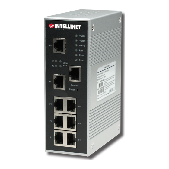
- Page 1 IndustrIal GIGabIt ManaGed ethernet swItch user Manual Models 503501, 503518, 503525 Model shown: 503501 INT-503501/503518/503525-UM-0408-01...
- Page 3 Industrial Gigabit ™ Managed ethernet switch: • Model 503501: 6-port 10/100Base-TX + 2-port 10/100/1000Base-TX, IP30 industrial standard • Model 503518: 6-port 10/100Base-TX + 2-port 1000Base-lX (sC) single-Mode, IP30 industrial standard • Model 503525: 6-port 10/100Base-TX + 2-port 1000Base-sX (sC) Multi-Mode, IP30...
-
Page 4: Table Of Contents
table of contents section page HARdWARe ....................5 dIN-Rail Installation ..................5 Wall-Mount Installation................5 Front-Panel Ports & Indicators ..............5 Bottom-Panel Connectors ................6 WeB MANAGeMeNT & CoNFIGURATIoN ...........6 Basic settings ...................7 Port Configuration ..................9 Redundancy ....................10 VlAN .......................13 Traffic Prioritization .................14 IGMP snooping ..................15 SNMP Configuration ................16 security ....................17 Warning ....................19... -
Page 5: Hardware
3. With the wall-mount panel Mounting clamp securely connected to the back of the switch, attach Wall-mount panel the switch to a wall or other suitably sturdy vertical surface. front-Panel Ports & Indicators Model 503518 Model 503501 Model 503525 hardware... -
Page 6: Bottom-Panel Connectors
1 Gigabit ethernet ports 2 Gigabit fiber ports 3 leds for: • PWR 1-3 (lighted indicates a power link to a dC power module [PWR 1 & 2] or the dC power jack [PWR 3]) • R.M, or ring master (lighted indicates this unit is serving as the master switch in a ring) •... -
Page 7: Basic Settings
The Main Interface screen introduces the main menu in the form of a left-side navigation column, with each section folder — Basic Settings, Port Configuration, Redundancy, VLAN and so on — opening to present sub-categories (as listed throughout the rest of this manual) that provide details and configuration options for that particular part of the Web-based management system. - Page 8 UTC Time Zone: Set the switch’s local time zone. Appendix A at the back of this manual lists the various local time zones for your reference. SNTP Server IP Address: set the sNTP server IP address. Daylight Saving Period: set the dsT beginning and ending dates.
-
Page 9: Port Configuration
Backup & Restore You can save current EEPROM (electrically erasable programmable read-only memory) values from the switch to the TFTP (Trivial File Transfer Protocol) server, then go to the TFTP restore configuration page to restore the EEPROM values. TFTP Server IP Address: enter the address. Restore File Name: Enter the file name. -
Page 10: Redundancy
Speed/Duplex: set the mode to “Auto-Negotiation,” “100 Full,” “100 Half,” “10 Full” or “10 Half.” Flow Control: enable or disable. Choose “Enable” to avoid packet loss when traffic is congested. Security: enable or disable port security. Click “Apply” to effect any changes. Port Status This screen presents the current settings established for each port in Port Control,... - Page 11 Ring Master: There should be one and only one ring master in a ring. However, if there are two or more switches that have Ring Master set to “Enable,” the switch with the lowest MAC address will be the actual ring master and others will serve as backup masters. 1st Ring Port: This is the primary port when this switch is the ring master.
- Page 12 Forward Delay Time (4–30): This is the amount of time a port waits before changing from its Rapid spanning Tree Protocol learning and listening states to the forwarding state. enter a value from 4 to 30. Path Cost (1–200000000): This is the cost of the path to the other bridge from this transmitting bridge at the specified port.
-
Page 13: Vlan
Vlan A Virtual lAN (VlAN) is a logical network grouping that limits the broadcast domain, allowing you to isolate network traffic. Only the members of the VLAN will receive traffic from other members of the same VLAN. Basically, creating a VLAN from a switch is logically equivalent to reconnecting a group of network devices to another Layer 2 switch;... -
Page 14: Traffic Prioritization
Add: Click to display the VlAN “add” screen (see below). Edit: Edit an existing VLAN configuration. Delete: Delete an existing VLAN. Help: Click to show the help file. Group Name: This is the VlAN name. VLAN ID: specify/enter the VlAN Id. Add: select a port you want to be joined to the .. -
Page 15: Igmp Snooping
queue packet are transmitted. • “Use a strict priority scheme” means the packets in a higher queue will be transmitted first until the higher queue is empty. Priority Type: In addition to “disable,” the drop-down menu offers the following options. •... -
Page 16: Snmp Configuration
IGMP Snooping Table: shows the current IP multicast list. Apply: Click to set the configurations. Help: Click to show the help file. SNMP Configuration SNMP (Simple Network Management Protocol) is the protocol developed to manage nodes (servers, workstations, routers, switches and hubs, etc.) on an IP network. SNMP enables network administrators to manage network performance, find and solve network problems, and plan for network growth. -
Page 17: Security
Add: Click to add a trap server profile. Remove: Click to remove a highlighted trap server profile. Help: Click to show the help file. security Five useful submenus are available to enhance the security of the Industrial Gigabit Managed ethernet switch: IP security, Port Security, MAC Blacklist, MAC Address Aging and 802.1x. - Page 18 MAC Address Aging This screen offers two options: You can set “MAC Address Table Aging Time” so that when the entered time expires any unused MAC addresses will be cleared from the MAC list; or you can select “Auto Flush MAC Address Table When Ports link down” to clear the list. MAC Address Table Aging Time: (0–3825): enter a number (of seconds) to set the timer as described above.
-
Page 19: Warning
warning This function is very important for managing the switch — with system alarms (SYSLOG, e-mail) or fault alarms — as it helps you monitor the switch status on a remote site. When events occur, the warning message will be sent to your appointed server or e-mail, or show as a lighted Fault LED on the switch’s front panel. -
Page 20: Monitoring
System Warning - Event Selection — sYsloG and sMTP (e-mail) are the two warning methods supported by the system. Check the corresponding boxes to enable the system event warning method. NOTE: These options can’t be selected when SYSLOG or SMTP is disabled. System Cold Start: sends an alert of a system restart. -
Page 21: Save Configuration
Port Monitoring Port monitoring supports TX (egress) only, RX (ingress) only and TX/RX monitoring. TX monitoring sends any data going out from selected TX source ports to a selected TX destination port, as well. likewise, RX monitoring sends any data coming in to selected RX source ports to a selected RX destination port, as well as sending the frame where it normally would have gone. - Page 22 3. on the subsequent Connect To screen, select a CoM port from the drop-down menu in the “Connect using” field. Click “OK.” 4. In the Port settings panel of the subsequent CoM1 Properties screen, confirm that the folowing options are selected.
-
Page 23: Cli Command Sets
Command Level Modes user EXEC — The user command available at the level of user is the subset of those available at the privileged level. Use this mode to 1) Enter Menu mode; 2) Display system information. Symbol of Command Level: e Access Method: Begin a session with your switch. - Page 24 system location [System Location] (G) — set the switch system location string. switch(config)#system location xxx system description [System Description] (G) — set the switch system description string. switch(config)#system description xxx system contact [System Contact] (G) — set the switch system contact window string. switch(config)#system contact xxx show system-info (E) —...
- Page 25 show dhcpserver clients (P) — Show client entries of the DHCP server. switch#show dhcpserver clinets show dhcpserver ip-binding (P) — Show IP-Binding information of the DHCP server. switch#show dhcpserver ip-binding no dhcpserver (G) — Disable the DHCP server function. switch(config)#no dhcpserver security enable (G) —...
- Page 26 bandwidth type all (I) — set the interface ingress limit frame type to “accept all frames.” switch(config)#interface fastEthernet 2 switch(config-if)#bandwidth type all bandwidth type broadcast-multicast-flooded-unicast (I) — set the interface ingress limit frame type to “accept broadcast, multicast, and flooded unicast frames.” switch(config)#interface fastEthernet 2 switch(config-if)#bandwidth type broadcast-multicast-flooded-unicast bandwidth type broadcast-multicast (I) —...
-
Page 27: Vlan Commands
aggregator activityport [Port Numbers] (G) — Set an activity port. switch(config)#aggregator activityport 2 aggregator group [GroupID] [Port-list] • lacp • workp [Workport] (G) — Assign a trunk group with LACP active, where [GroupID] is 1 to 3; [Port-list] is a member port list, which could be a port range (e.g., 1-4) or a port list separated by a comma (e.g., 2, 3, 6);... - Page 28 vlan 8021q aggregator [TrunkID] • trunk-link tag [TaggedVID List] (V) — Assign a trunk link for VlAN by trunk group. switch(vlan)#vlan 8021q aggregator 3 trunk-link tag 2,3,6,99 switch(vlan)#vlan 8021q aggregator 3 trunk-link tag 3-20 vlan 8021q aggregator [PortNumber] • hybrid-link untag [UntaggedVID] • tag [TaggedVID List] (V) —...
- Page 29 show spanning-tree (E) — display a summary of the spanning Tree states. switch>show spanning-tree no spanning-tree (G) — disable spanning Tree. switch(config)#no spanning-tree QoS Commands qos policy [weighted-fair|strict] (G) — select Qos policy scheduling. switch(config)#qos policy weighted-fair qos prioritytype [port-based|cos-only|tos-only|cos-first|tos-first] (G ) — set the Qos priority type.
- Page 30 show mac-address-table (P) — show all MAC addresses in the table. switch#show mac-address-table show mac-address-table static (P) — show the static MAC address table. switch#show mac-address-table static show mac-address-table filter (P) — Show the filtered MAC address table. switch#show mac-address-table filter no mac-address-table static hwaddr [MAC] (I) —...
- Page 31 monitor tx (G) — set the TX destination port of the monitor function. switch(config)#monitor tx show monitor (P) — show port monitor information. switch#show monitor monitor [RX|TX|Both] (I) — Configure the source port of the monitor function. switch(config)#interface fastEthernet 2 switch(config-if)#monitor RX show monitor (I) —...
- Page 32 8021x misc reauthperiod [sec.] (G) — Use the 802.1x misc reauth period global configuration command to set the reauth period. switch(config)# 8021x misc reauthperiod 3000 8021x portstate [disable | reject | accept | authorize] (I) — Use the 802.1x port state interface configuration command to set the state of the selected port.
- Page 33 show smtp (P) — show the information of sMTP. switch#show smtp no smtp (G) — disable the sMTP function. switch(config)#no smtp event device-cold-start [Systemlog|SMTP|Both] (G) — Set the cold start event type. switch(config)#event device-cold-start both event authentication-failure [Systemlog|SMTP|Both] (G) — set the authentication failure event type.
- Page 34 sntp daylight-offset [Minute] (G) — Set the offset of Daylight Saving Time. If the SNTP function is inactive, this command can’t be applied. switch(config)#sntp daylight-offset 3 sntp ip [IP] (G) — Set the SNTP server IP. If the SNTP function is inactive, this command can’t be applied.
-
Page 35: Appendix A
aPPendIx a Refer to this table as needed when setting the switch’s local time zone in the “UTC (Coordinated Universal Time) Time Zone” field in the SNTP Configuration section (see Page 8). Local Time Zone Conversion from UTC Time at 12:00 UTC November Time Zone -1 hour 11 am... -
Page 36: Specifications
• Ieee 802.3u (100Base-TX Fast ethernet) • IEEE 802.3x (Flow Control, for full duplex mode) • SNMPv1/v2c/v3 (Simple Network Management Protocol) General • Media support, Model 503501: - 10Base-T Cat3, 4, 5 UTP/sTP RJ-45 - 100Base-TX Cat5 UTP/sTP RJ-45 - 1000Base-T Cat5 UTP/sTP RJ-45 •... - Page 37 • shock: IeC 60068-2-27 • Free fall: IeC 60068-2-32 • Vibration: IeC 60068-2-6 • MTBF: - Model 503501: 276,970 hours - Model 503518: 270,265 hours - Model 503525: 273,198 hours Calculated MTBF is based on MIl-HdBK-217F (Military Handbook) standard Package Contents •...
- Page 40 INTELLINET NETWORK SOLUTIONS ™ offers a complete line of active and passive networking products. Ask your local computer dealer for more information or visit www.intellinet-network.com. Copyright © INTELLINET NETWORK SOLUTIONS All products mentioned are trademarks or registered trademarks of their respective owners.
Need help?
Do you have a question about the 503501 and is the answer not in the manual?
Questions and answers