
Related Manuals for Intellinet 505710 Series


Summary of Contents for Intellinet 505710 Series
- Page 1 Industrial Slim Type Fast Ethernet Rail Switch 505710 / 505628 Series User’s Manual Version 1.0 May, 2008.
-
Page 2: Table Of Contents
Mount 505710 / 505628 Series on the wall ..............4 Hardware Overview..................6 Front Panel ..........................6 Front Panel LEDs .......................9 Bottom Panel ........................9 Rear Panel .........................10 Cables ......................11 Ethernet Cables ........................ 11 4.1.1 100BASE-TX/10BASE-T Pin Assignments..............11 Technical Specifications ................12 INTELLINET NETWORK SOLUTIONS... -
Page 3: Overview
• Supports IEEE 802.3x flow control on full duplex and backpressure on half duplex • Supports 2048 MAC address entries • LEDs for power, link/activity, power fault indicator • DIN rail or wall mounting • Terminal block to provide dual power inputs with reverse-polarity protection INTELLINET NETWORK SOLUTIONS... -
Page 4: Hardware Installation
DIN-Rail. It is easy to install the switch on the DIN-Rail: 2.1.1 Mount 505710 / 505628 Series on DIN-Rail Step 1: Slant the switch and mount the metal spring to DIN-Rail. Metal Spring Step 2: Push the switch toward the DIN-Rail until you heard a “click” sound. INTELLINET NETWORK SOLUTIONS... -
Page 5: Wall Mounting Installation
Mount 505710 / 505628 Series on the wall Step 1: Remove DIN-Rail kit. Step 2: Use 6 screws that can be found in the package to combine the wall mount panel. Just like the picture shows below: INTELLINET NETWORK SOLUTIONS... - Page 6 The screws specification shows in the following two pictures. In order to prevent switches from any damage, the screws should not larger than the size that used in 505710 / 505628 series switches. Pozidrive Step 3: Mount the combined switch on the wall. INTELLINET NETWORK SOLUTIONS...
-
Page 7: Hardware Overview
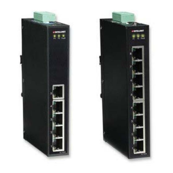
The following table describes the labels that stick on the IES-1080 / 1062 series. Port Description 10/100 RJ-45 fast 10/100Base-T(X) RJ-45 fast Ethernet ports support auto-negotiation. Ethernet ports Default Setting : Speed: auto Duplex: auto Flow control : disable INTELLINET NETWORK SOLUTIONS... - Page 8 1. LED for PWR1&PW2. When the PWR1 links, the green led will be light on. 2. LED for Fault Relay. When the power fault occurs, the amber LED will be light on. 3. 10/100Base-T(X) Ethernet ports. 4. LED for Ethernet ports status. 5. Model name INTELLINET NETWORK SOLUTIONS...
- Page 9 1. LED for PWR1&PW2. When the PWR1 links, the green led will be light on. 2. LED for Fault Relay. When the power fault occurs, the amber LED will be light on. 3. 10/100Base-T(X) Ethernet ports. 4. LED for Ethernet ports status. 5. Model name INTELLINET NETWORK SOLUTIONS...
-
Page 10: Front Panel Leds
LNK / ACT Green Blinking Data transmitted. 3.3 Bottom Panel The bottom panel components of IES-1080 / 1062 Series are shown as below: 1. Terminal block includes: PWR1, PWR2 (12-48V DC) and Relay output (1A@24VDC). 2. Power Fault Check INTELLINET NETWORK SOLUTIONS... -
Page 11: Rear Panel
505710 / 505628 Series User’s Manual 3.4 Rear Panel The components in the rare of IES-1080 / 1062 Series are shown as below: 1. Screw holes for wall mount kit. 2. DIN-Rail kit INTELLINET NETWORK SOLUTIONS... -
Page 12: Cables
The 505710 / 505628 Series switches support auto MDI/MDI-X operation. You can use a straight-through cable to connect PC to switch. The following table below shows the 10BASE-T/ 100BASE-TX MDI and MDI-X port pin outs. MDI/MDI-X pins assignment INTELLINET NETWORK SOLUTIONS... -
Page 13: Technical Specifications
Green : Power LED x 2 Fault indicator Yellow : Indicate PWR1 or PWR2 failure 10/100TX RJ45 port Green for port Link/Act. Yellow for Duplex/Collision indicator Fault contact Relay Relay output to carry capacity of 1A at 24VDC INTELLINET NETWORK SOLUTIONS... - Page 14 Temperature Operating Humidity 5% to 95% Non-condensing Regulatory approvals FCC Part 15, CISPR (EN55022) class A EN61000-4-2 (ESD), EN61000-4-3 (RS), EN61000-4-4 (EFT), EN61000-4-5 (Surge), EN61000-4-6 (CS), EN61000-4-8, EN61000-4-11 Shock IEC60068-2-27 Free Fall IEC60068-2-32 Vibration IEC60068-2-6 Safety EN60950 INTELLINET NETWORK SOLUTIONS...
- Page 15 505710 / 505628 Series User’s Manual INTELLINET NETWORK SOLUTIONS™ offers a complete line of active and passive networking products. Ask your local computer dealer for more information or visit www.intellinet-network.com Copyright © INTELLINET NETWORK SOLUTIONS All products mentioned are trademarks or registered trademarks of their respective owners.
Need help?
Do you have a question about the 505710 Series and is the answer not in the manual?
Questions and answers