Table of Contents
Advertisement
Advertisement
Table of Contents

Related Manuals for Sunny Health & Fitness ASUNA 6100


Summary of Contents for Sunny Health & Fitness ASUNA 6100
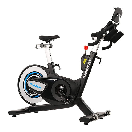
- Page 1 ASUNA 6100 SPRINTING COMMERCIAL INDOOR CYCLING BIKE Owner's Manual Made in China...
-
Page 2: Table Of Contents
INDEX IMPORTANT SAFETY INFORMATION ..............1 EXPLODED DRAWING ..................... 2 PARTS LIST ......................3 ASSEMBLY PARTS LIST / TOOLS & HARDWARE ..........4 ASSEMBLY INSTRUCTIONS ................5-8 USER INSTRUCTIONS ..................9-12 MAINTENANCE ....................13-15 EXERCISE INSTRUCTIONS ................16-17 SPD PEDAL INSTALLATION ..................18 ME TER INS T RUCTI ON ........ -
Page 3: Important Safety Information
IMPORTANT SAFETY INFORMATION We thank you for choosing our product. To ensure your safety and health, please use this equipment correctly. It is important to read this entire manual before assembling and using the equipment. Safe and effective use can only be assured if the equipment is assembled, maintained, and used properly. -
Page 4: Exploded Drawing
Exploded Drawing 2... -
Page 5: Parts List
P a r t s L i s t DESCRIPTION DESCRIPTION Frame Assembly Nylon Nut (m8*p1.25) Hex Blind Nut Tablet Holder Assembly Bottom Bracket Set Tablet Holder Left Cup Of Bottom Bracket Flat Washer Sus304 m6(d12*d6.5*2.0t) Bottom Bracket Left Fixed Circle Flat Cross Hex Screw Sus304 (m6*p1.0*55l) Right Crank Seat Slider... -
Page 6: Assembly Parts List / Tools & Hardware
Tools & Hardware L-Hex Wrench 4mm/60Lx25L #61Hex Socket Screw (2PCS) #63Hex-Socket Screw (4PCS) L-Hex Wrench 5mm/76Lx27L #62Flat Washer (2PCS) Combination Cross Wrench Tablet Holder Handlebar Adjustment Knob 13/14/15/mm #34Flat Washer (4PCS) (1PCS) (1PCS) #120 #121 #122 #123 Open end wrench Fixing Stator For Meter Meter Heart Rate Strap... -
Page 7: Assembly Instructions
Assembly Instructions STEP 1: Attach the Front and Rear Stabilizers (NO. 104 and NO. 116) to the Main Frame (NO. 1) using 4 Hex Screws (NO. 63), 4 Flat Washers (NO. 34). Tighten and secure using Hex Wrench (B). Handlebar Adjustment Knob Assembly Remove the Handlebar Adjustment Knob (NO. - Page 8 Assembly Instructions STEP 2: Insert the Handlebar Post (NO. 84) into the front tube of the Main Frame (NO. 1). Use the Handlebar Adjustment Knob (NO.41) to adjust the handlebar to the desired height and secure the handlebar in position. Please connect the Meter connection Wire A (NO. 124) and Meter Connection Wire B (NO.125) when you insert the Handlebar Post (No.
-
Page 9: Right Crank
Assembly Instructions STEP 3: IMPORTANT:Please read these instructions carefully. Failure to do so may cause permanent damage to your bike. Connect Pedals L/R (36) onto the Left and Right Crank Arms (NO. 6 and NO. 11). Before you begin, immobilize the crank arms by turning the Knob (NO. 25) all the way to the right. - Page 10 Assembly Instructions STEP 4: The assembly is complete! Before beginning use of the equipment, please be sure to inspect the entire bike carefully. Ensure that all moving and stationary parts have been properly installed and are operational; inspect all screws, nuts, and bolts to make sure that they are tightened and secure.
-
Page 11: User Instructions
User Instructions This section will instruct you on how to properly use and make adjustments to components on the bike. Items which will be covered include seat adjustment, handlebar adjustment, resistance adjustment, using the emergency brake, pedal strap adjustment, dismounting the bike, moving the bike, and leveling the bike. NOTE: Properly assembling the equipment before use is very important, please be sure to follow all instructions as detailed in the assembly instructions section of the owner’s... - Page 12 User Instructions SEAT SLIDER ADJUSTMENT 1.Simply loosen the Adjustment Knob (NO. 77) counter-clockwise and slide the Seat (NO. 80) forward or backwards to the desired position. 2. Once the seat has been set in the desired position, turn the Adjustment Knob (NO.
- Page 13 User Instructions RESISTANCE ADJUSTMENT In order to change the intensity of your workout, the resistance can be easily adjusted at any time while riding. Turn the Resistance Knob (NO. 25) clockwise (+) to increase the level of resistance. Turn the Resistance Knob (NO. 25) counterclockwise (-) to decrease the level of resistance.
- Page 14 User Instructions DISMOUNTING THE BIKE WARNING: Do NOT attempt to dismount or remove your feet from the pedals until both the flywheel and the pedals/crank have come to a complete stop. Failure to follow this warning may lead to loss of control and/or serious injury. Here are a few examples of how to safely and properly dismount the bike: 1.Reduce the pedal speed until the pedals/crank come to a complete stop.
-
Page 15: Maintenance
Maintenance BELT DRIVE TENSION The belt on this bike was pre-tensioned and pre-lubricated prior to being shipped. The belt should not require any adjustments upon the bikes initial uses. However, you may need to make minor tension adjustments over time. Note:Make sure you adjust the tension equally on both sides when tightening or loosening to ensure that the flywheel is in alignment with the frame. - Page 16 Maintenance IMPORTANT: Safe and effective use of your equipment can only be assured if the equipment is assembled, maintained, and used properly. Any components found to be worn and/or damaged should be replaced before continuing use of the equipment. Equipment should only be used and stored indoors.
-
Page 17: Seat Slider
Maintenance Weekly Maintenance: This maintenance is the upkeep of the overall performance. Check for vibration and loose parts during this inspection. Part Recommended Action Cleaner Lubricant Toe Clips/ Inspect for wear and tear. Re-tighten if Toe Straps loose or disconnected. Replace if needed. Tighten all the frame hardware (Bolts, nuts, Hardware screws) -
Page 18: Exercise Instructions
Exercise Instructions NOTE: Using the ASUNA Magnetic Turbo Commercial Indoor Cycling Bike will provide you with several benefits. It will improve your physical fitness, tone your muscles, and in conjunction with a calorie controlled diet, it can also help you lose weight. 1. - Page 19 Exercise Instructions 3. THE COOL-DOWN PHASE: This stage is to let your cardio-vascular system and muscles wind down. Start by reducing your tempo and continuing for approximately 5 minutes. The stretching exercises (warm-up phase) should now be repeated. Again, remember not to force or jerk your muscles into the stretch.
-
Page 20: Spd Pedal Installation
S P DP edal Installation Included with your equipment is a set of SPD cleats compatible to the SPD pedals. Your SPD pedals have a standard pedal with toe cage on one side, which allows you to use regular shoes, as well as the SPD side on the other to attach your cleats. In order to use the SPD pedal, you would have to own a pair of SPD shoes designed to fit the cleats. -
Page 21: Meter
Me t e r I n st r u c t i on DISPLAY FUNCTION: ITEM DESCRIPTION . In SCAN mode, press MODE/ENTER key to choose functions. . Automatically scan through each mode in sequence every 6 seconds. SCAN . The sequence of display when press MODE/ENTER key : TIME→ DIST→CAL→ PULSE→RPM/SPEED . -
Page 22: Me Ter Ins T Ructi On
Met er I n str uct ion KEY FUNCTION: ITEM DESCRIPTION . Press SET key to increase value. Press and hold the key to increase value faster. . TIME setting range: 00:00~99:00 (Each increment is 1:00) . CAL setting range: 0~9990 (Each increment is 10) . - Page 23 Meter I nst r u c t i on OPERATION 1.Workout setting ▪ Press MODE/ENTER key to select the function of TIME, DISTANCE, CALORIES and PULSE. Use SET Key for setting and press MODE/ENTER key for confirmation. ▪ For instance the time set-up, when the time value is blinking, you can use SET Key to adjust the number.
-
Page 24: Chest Belt Instruction
Chest Belt Instruction I. Product picture: II. Standard wearing method: Figure 1 Figure 2 Figure 3 III. Measuring your heart rate: 1. Wet your skin with water before putting on the chest belt, so the belt can detect the signal better. -
Page 25: Product Specifications
Product Specifications Dimensions 59″L x 22″W x 48.4″H Assembled Unit Weight 126.7 lbs (57.5 kg) Packaged Weight 138.9 lbs (63 kg) Maximum User Weight 350 lbs (160 kg) 23 Version 1.0...
Need help?
Do you have a question about the ASUNA 6100 and is the answer not in the manual?
Questions and answers