Advertisement
Quick Links
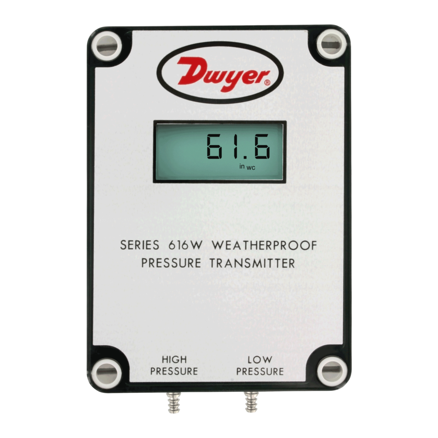
Series 616W Differential Pressure Transmitter
Specifications - Installation and Operating Instructions
The SERIES 616W Differential Pressure Transmitter senses the pressure of air and
non-combustible, compatible gases and sends a standard 4 to 20 mA or selectable
0 to 5/0 to 10 VDC output signal. All models, including those featuring an LCD, are
factory calibrated to specific ranges. Positive, negative, and differential pressures
can be measured within a full scale accuracy of ±0.25%. This weatherproof unit is
enclosed in a polycarbonate case, rated IP66/NEMA 4X. The span and zero controls
are for use when checking calibration, and are not intended for re-ranging.
Series 616W Transmitter Models & Ranges
MODEL CHART
Model
Range
616W-2
0 to 6 in w.c.
616W-3
0 to 10 in w.c.
616W-4
0 to 20 in w.c.
616W-5
0 to 40 in w.c.
616W-6
0 to 100 in w.c.
616W-7
0 to 200 in w.c.
616W-2-LCD
0 to 6 in w.c.
616W-3-LCD
0 to 10 in w.c.
616W-4-LCD
0 to 20 in w.c.
616W-5-LCD
0 to 40 in w.c.
616W-6-LCD
0 to 100 in w.c.
616W-7-LCD
0 to 200 in w.c.
616W-6B-LCD
3-0-3 in w.c.
616W-10B-LCD
5-0-5 in w.c.
616W-20B-LCD
10-0-10 in w.c.
616W-2M-LCD
0 to 1.5 kPa
616W-3M-LCD
0 to 2.5 kPa
616W-4M-LCD
0 to 5 kPa
616W-5M-LCD
0 to 10 kPa
DWYER INSTRUMENTS, INC.
P.O. BOX 373 • MICHIGAN CITY, INDIANA 46360, U.S.A.
3-1/8
[79.38]
1-3/16
[30.18]
3-3/4 [95.25]
Max. Pressure Digital Display
10 psig
–
10 psig
–
20 psig
–
20 psig
–
15 psig
–
45 psig
–
10 psig
0 to 6.00
10 psig
0 to 10.00
20 psig
0 to 20.0
20 psig
0 to 40.0
15 psig
0 to 100.0
45 psig
0 to 200.0
10 psig
-3.00-0-3.00
10 psig
-5.00-0-5.00
10 psig
-10.00-0-10.00
68.9 kPa
0 to 1.50
68.9 kPa
0 to 2.50
137.8 kPa
0 to 5.00
137.8 kPa
0 to 10.0
Table 1
1-1/4
[31.75]
4-1/2
[114.30]
5-1/8
1-5/16 [33.32] TYP
[130.18]
7/16 OR 5/8
[11.13 OR 15.88]
TYP
1/8 AND 3/16
[3.18 AND 4.76]
I.D. TUBING
1-1/4
3/4 [19.05] TYP
[31.75]
2-1/8
[53.98]
SPECIFICATIONS
Service: Air and non-combustible, compatible gases.
Wetted Materials: Consult factory.
Accuracy: 0.25% FS @ 77°F (25°C), display accuracy ±0.5%.
Thermal Effect: ±0.02% FS/°F (±0.036% FS/°C).
Stability: ±1% FS/yr.
Temperature Limits: 14 to 185°F (-10 to 85°C).
Pressure Limits: See chart.
Power Requirements: 10 to 35 VDC (2-wire), 17 to 36 VDC, or isolated 21.6 to 33
VAC (3-wire).
Output Signal: 4 to 20 mA (2-wire), 0 to 5 VDC, or 0 to 10 VDC (3-wire)
Zero and Span Adjustments: Push buttons.
Loop Resistance: Current Output: 0 to 1250 Ω (max); Voltage Output: Load
resistance 1 kΩ (min).
Current Consumption: 40 mA max.
Electrical Connections: 3-wire removable European style terminal block for 16 to
26 AWG.
Process Connections: Barbed, dual size to fit 1/8" and 3/16" (3.12 and 4.76 mm)
I.D. rubber or vinyl tubing.
Enclosure Rating: NEMA 4X (IP66).
Mounting Orientation: Any orientation.
Weight: Without LCD: 8.8 oz (249 g); With LCD: 9.6 oz (272 g).
Agency Approvals: CE.
Phone: 219/879-8000
Fax: 219/872-9057
Bulletin P-616W
Ø3/16 [4.76]
MOUNTING HOLES
TYP 4 PLACES
3-1/8
[79.38]
www.dwyer-inst.com
e-mail: info@dwyermail.com
4-17/32
[115.09]
Advertisement

Related Manuals for Dwyer Instruments 616W-2


Summary of Contents for Dwyer Instruments 616W-2
- Page 1 0 to 5 kPa 137.8 kPa 0 to 5.00 616W-5M-LCD 0 to 10 kPa 137.8 kPa 0 to 10.0 Table 1 DWYER INSTRUMENTS, INC. Phone: 219/879-8000 www.dwyer-inst.com P.O. BOX 373 • MICHIGAN CITY, INDIANA 46360, U.S.A. Fax: 219/872-9057 e-mail: info@dwyermail.com...
- Page 2 INSTALLATION 2-Wire 4 to 20 mA Current Operation 1. Location: Select a clean, dry mounting location free from excess vibration where the temperature will remain between 14 to 185°F (-10 to 85°C). Distance from the Do not exceed specified supply voltage ratings. Permanent CAUTION receiver is limited only by total loop resistance.
- Page 3 3-Wire 0 to 10 V and 0 to 5 V Voltage Operation For the current output, the maximum allowable loop resistance (wiring + receiver resistance) is dependent on the power supply. The maximum loop voltage drop must not reduce the transmitter voltage below 17 V. The maximum loop resistance can be Do not exceed specified supply voltage ratings.
- Page 4 ©Copyright 2017 Dwyer Instruments, Inc. Printed in U.S.A. 6/17 FR# 444343-10 Rev. 4 DWYER INSTRUMENTS, INC. Phone: 219/879-8000 www.dwyer-inst.com P.O. BOX 373 • MICHIGAN CITY, INDIANA 46360, U.S.A. Fax: 219/872-9057 e-mail: info@dwyermail.com...
Need help?
Do you have a question about the 616W-2 and is the answer not in the manual?
Questions and answers