Advertisement
Quick Links
Advertisement

Related Manuals for Planet IGS-500T


Summary of Contents for Planet IGS-500T
- Page 1 Compact Industrial 5-/8-Port Gigabit Ethernet Switch IGS-500T/IGS-800T User's Manual...
- Page 2 3.2 LED Definition: ..................7 3.3 Switch Upper Panel ................. 7 3.4 Wiring the Power Inputs ................8 3.5 Wiring the Fault Alarm Contact (IGS-500T only) ........10 3.6 Grounding the Device ................11 4. Installation ....................12 4.1 DIN-rail Installation ................12 4.2 Wall Mounting ..................
- Page 3 1. Package Contents Thank you for purchasing PLANET Compact Industrial 5-port Gigabit Ethernet Switch, IGS-500T. In the following sections, the term “Industrial Gigabit Ethernet Switch” means the IGS-500T. Open the box of the Industrial Gigabit Ethernet Switch and carefully unpack it. The...
- Page 4 2. Product Specifications Model IGS-500T IGS-800T Hardware Specifications 5 10/100/1000BASE-T RJ45 8 10/100/1000BASE-T RJ45 Copper Ports auto-MDI/MDI-X ports auto-MDI/MDI-X ports Removable 6-pin terminal block Removable 4-pin terminal Pin 1/2 for Power 1; block Connector Pin 3/4 for fault alarm; Pin 1/2 for Power 1; Pin...
- Page 5 Jumbo Frame 9Kbytes Back pressure for half duplex Flow Control IEEE 802.3x pause frame for full duplex Standards Conformance Regulatory FCC Part 15 Class A, CE Compliance IEC 60068-2-32 (free fall) Stability Testing IEC 60068-2-27 (shock) IEC 60068-2-6 (vibration) IEEE 802.3 Ethernet IEEE 802.3u Fast Ethernet Standards IEEE 802.3ab Gigabit Ethernet...
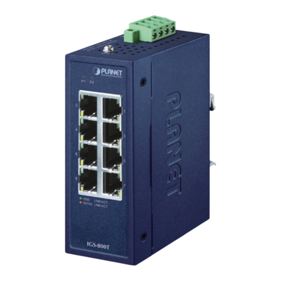
- Page 6 3.1 Switch Front Panel The front Panels of the Industrial Gigabit Ethernet Switches consist of Ethernet interfaces and LED indicators. Front View P2 Alarm 1000 1000 LNK/ACT 10/100 LNK/ACT 10/100 IGS-500T IGS-800T Figure 1: IGS-500T Front View Figure 2: IGS-800T Front View...
- Page 7 1 2 3 4 DC Input: 9-48V , 0.28A max. AC Input: 24V , 0.3A max. PWR1 Alarm PWR2 DC Input: 9-48V , 1A max. PWR1 PWR2 AC Input: 24V , 0.5A max. Figure 3: IGS-500T Top View Figure 4: IGS-800T Top View...
- Page 8 éviter tout choc électrique. IGS-500T 1. Insert positive and negative DC power wires into contacts 1 and 2 for POWER 1, or contacts 5 and 6 for POWER 2.
- Page 9 3. Tighten the wire-clamp screws for preventing the wires from loosening. Power 1 Alarm Power 2 IGS-800T 1. Insert positive and negative DC power wires into contacts 1 and 2 for POWER 1, or contacts 3 and 4 for POWER 2. 1 2 3 4 DC Input: 9-48V , 1A max.
- Page 10 24V AC. 2. Utilisez une entrée d’alimentation lorsque vous utilisez 24V AC.. 3.5 Wiring the Fault Alarm Contact (IGS-500T only) The fault alarm contacts are in the middle of the terminal block connector as the picture shows below. Inserting the wires, the Industrial Gigabit Ethernet Switch will detect the fault status of the power failure and then forms an open circuit.
- Page 11 3.6 Grounding the Device Users MUST complete grounding the device wired with a power cord adapter or power supply source; a sudden lightning could cause fatal damage to the device. Max. Fault Alarm Loading: 24V, 1A 1 2 3 4 5 6 1 2 3 4 DC Input: 9-48V , 0.28A max.
- Page 12 This section guides you to installing the Industrial Gigabit Ethernet Switch on the DIN rail and wall. Please read this chapter completely before continuing. This following pictures show how to install the device. However, the device in the picture is not IGS-500T/IGS-800T. 4.1 DIN-rail Installation Figure 5: DIN-rail Mounting Place the bracket on the back of the device and with the given 3 screws, tighten them. Slide the device with the bracket mounted through the DIN-rail to finish the...
- Page 13 4.2 Wall Mounting Figure 6: Wall Mounting Place both mounting plates on the back of the device, and tighten them with the given screws. Then put the device with the plates mounted on the wall, and screw them to finish the installation. 4.3 Side Wall Mounting Figure 7: Side Wall Mounting Place the two mounting plates on the bottom of the device, and tighten them with the given screws.
- Page 14 The LED indicators are also located on the front panel. IGS-500T Top View Mounting Kit Side View Front View Side View Rear View P2 Alarm 1000 DIN-Rail Kit 10/100 IGS-500T Bottom View Mounting Kit Unit: mm Figure 8: IGS-500T Three-View Diagram...
- Page 15 IGS-800T Top View Mounting Kit Side View Front View Side View Rear View DIN-Rail Kit 1000 LNK/ACT 10/100 LNK/ACT Mounting Kit IGS-800T Bottom View Dimensions (W x D x H): 41 x 70 x115 mm Figure 9: IGS-800T Three-View Diagram...
- Page 16 Customer Support Thank you for purchasing PLANET products. You can browse our online FAQ resource on PLANET web site first to check if it could solve your issue. If you need more support information, please contact PLANET switch support team.
- Page 17 FCC Warning This equipment has been tested and found to comply with the regulations for a Class A digital device, pursuant to Part 15 of the FCC Rules. These limits are designed to provide reasonable protection against harmful interference when the equipment is operated in a commercial environment.
- Page 18 WEEE Warning To avoid the potential effects on the environment and human health as a result of the presence of hazardous substances in electrical and electronic equipment, end users of electrical and electronic equipment should understand the meaning of the crossed-out wheeled bin symbol. Do not dispose of WEEE as unsorted municipal waste and have to collect such WEEE separately.
Need help?
Do you have a question about the IGS-500T and is the answer not in the manual?
Questions and answers