
Related Manuals for Stanley CT10056DH


Summary of Contents for Stanley CT10056DH
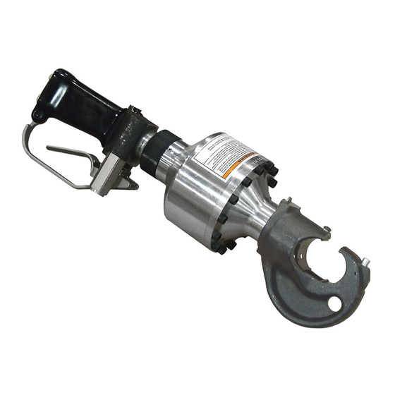
- Page 1 CT10 HYDRAULIC CRIMPING TOOL USER’S MANUAL Safety, Operation and Maintenance © 2014 Stanley Black & Decker, Inc. New Britain, CT 06053 U.S.A. 58545 5/2017 Ver. 11...
-
Page 3: Table Of Contents
Stanleyhydraulics.com and select the Company tab, Warranty. (NOTE: The warranty Validation record must be submitted to validate the warranty). SERVICING: This manual contains safety, operation, and routine maintenance instructions. Stanley Hydraulic Tools recommends that servicing of hydraulic tools, other than routine maintenance, must be performed by an authorized and certified dealer. -
Page 4: Safety Symbols
SAFETY SYMBOLS Safety symbols and signal words, as shown below, are used to emphasize all operator, maintenance and repair actions which, if not strictly followed, could result in a life-threatening situation, bodily injury or damage to equip- ment. This is the safety alert symbol. It is used to alert you to potential personal injury hazards. -
Page 5: Safety Precautions
SAFETY PRECAUTIONS Tool operators and maintenance personnel must always comply with the safety precautions given in this manual and on the stickers and tags attached to the tool and hose. These safety precautions are given for your safety. Review them carefully before operating the tool and before performing general maintenance or repairs. -
Page 6: Tool Stickers & Tags
USE ONLY PARTS AND REPAIR USE ONLY PARTS AND REPAIR PROCEDURES APPROVED BY PROCEDURES APPROVED BY and understand the safety STANLEY AND DESCRIBED IN THE OPERA- STANLEY AND DESCRIBED IN THE OPERA- TION MANUAL. TION MANUAL. instructions listed on this... -
Page 7: Hose Types
The rated working pressure of the hydraulic hose must be equal to or higher than the relief valve setting on the hydraulic system.There are three types of hydraulic hose that meet this requirement and are authorized for use with Stanley Hydraulic Tools. -
Page 8: Hose Recommendations
HOSE RECOMMENDATIONS HYDRAULIC CIRCUIT CONTROL PANEL PRESSURE RETURN RETURN PRESSURE TOOL 8 CT10 USER MANUAL... -
Page 9: Htma Requirements
HTMA / EHTMA REQUIREMENTS HTMA / EHTMA REQUIREMENTS HTMA TOOL TYPE HYDRAULIC SYSTEM REQUIREMENTS TYPE I TYPE II TYPE RR TYPE III 4-6 gpm 7-9 gpm 9-10.5 gpm 11-13 gpm Flow Range (15-23 lpm) (26-34 lpm) (34-40 lpm) (42-49 lpm) 1500 psi 1500 psi 1500 psi... -
Page 10: Operation
The CT10 Hydraulic Crimping Tool can be configured for either open-center or closed-center operation. The current setting is easily determined by looking at the gap between the adapter and the cylinder: Kearney PH2 Style Stanley Y35 Style C-Frame Retainer Die Yoke 10 CT10 USER MANUAL... - Page 11 • If the die load has been verified, select a set of dies to match the sleeve or connector to be crimped. 3. Tighten the capscrew to retain the die. TO INSTALL DIES ON STANLEY OR BURNDY Make sure the hydraulic system control valve is in the OFF CRIMPING HEADS - Y35 STYLE position when coupling or uncoupling the hoses.
- Page 12 OPERATION 2. Connect the tool to an appropriate hydraulic power source. The hydraulic fluid temperature should be at least 80°F/27°C Follow the Hydraulic Hose Connection safety guidelines and for this test. instructions in this section. If possible, use the hydraulic power source you plan to use for crimping.
-
Page 13: Storage
OPERATION STORAGE 2. Remove any trapped air from the tool by squeezing the trigger 4 or 5 times to advance and retract the piston nearly a full stroke. Replace any damaged or missing safety labels and tags before storing the tool. Clean, dry and lubricate moving parts 3. -
Page 14: Equipment Protection & Care
The circuit RETURN hose (with female quick disconnect) is connected to the opposite port. Do not reverse circuit flow. This can cause damage to internal seals. • Always replace hoses, couplings and other parts with replacement parts recommended by Stanley Hydraulic Tools. Supply hoses must have a minimum working pressure rating of 2500 psi/172 bar. -
Page 15: Troubleshooting
Relief valve set too low. Increase relief valve pressure. Dirt or obstruction between dies. Remove obstruction. Clean die area. Contact an authorized Stanley Piston seal worn or damaged. distributor. Improper die set for wire and Install proper die set. -
Page 16: Specifications
SPECIFICATIONS Capacity (depending on model) .................500 MCM Copper to 1033 MCM Aluminum Crimping Force ....................12 tons @ 1650 psi / 10,886 kg @ 114 bar Pressure Range ...........................1650-2500 psi/114-172 bar Flow Range .............................. 3-9 gpm/11-34 lpm Optimum Flow ..............................8 gpm / 30 lpm Porting ..................................3/8 NPT Hose Whips &... - Page 17 NOTES CT10 USER MANUAL 17...
-
Page 18: Ct10016N Parts Illustration
CT10016N PARTS ILLUSTRATION THIS IS A NEWER MODEL CYLINDER HEAD AND C-FRAME. THE CYLINDER HEAD (ITEM 38) HAS A THREAD DIAMETER OF M60X1.5 (METRIC) AND A THREAD LENGTH OF 1.100. CHECK THESE DIMENSIONS ON YOUR CYLINDER HEAD BEFORE ORDERING PARTS TO MAKE SURE YOU ARE ORDERING THE CORRECT PARTS. -
Page 19: Ct10016N Parts List
CT10016N PARTS LIST Item Part No. Qty Description Item Part No. Qty Description 58499 Sticker 00118 Retaining Ring 58583 T-Seal 00144 Capscrew 58594 Retaining Ring 07626 O-Ring 67277 Set Screw 09330 O-Ring 67259 Check Valve Assembly 00294 O-Ring 67280 00360 O-Ring 58551 Seal Kit (Includes Items 3-6,... -
Page 20: Ct10056Dh Parts Illustration
CT10056DH PARTS ILLUSTRATION THIS IS AN NEWER MODEL CYLINDER HEAD AND C-FRAME. THE CYLINDER HEAD (ITEM 38) HAS A THREAD DIAMETER OF M60X1.5 (METRIC) AND A THREAD LENGTH OF 1.100. CHECK THESE DIMENSIONS ON YOUR CYLINDER HEAD BEFORE ORDERING PARTS TO MAKE SURE YOU ARE ORDERING THE CORRECT PARTS. -
Page 21: Ct10056Dh Parts List
CT10056DH PARTS LIST Item Part No. Description Item Part No. Description 58499 Sticker 00118 Retaining Ring 58583 T-Seal 00144 Capscrew 58594 Retaining Ring 07626 O-Ring 67259 Check Valve Assy 09330 O-Ring 06326 Washer 00294 O-Ring 03014 Washer 00360 O-Ring 67281... -
Page 22: Ct10056N Parts Illustration
CT10056N PARTS ILLUSTRATION 22 CT10 USER MANUAL... -
Page 23: Ct10056N Parts List
CT10056N PARTS LIST Item Part Description Item Part Description 00118 Retaining Ring 58499 Sticker 00144 Capscrew 58513 Cylinder Head 07626 O-Ring 58583 T-Seal 09330 O-Ring 58594 Retaining Ring 00294 O-Ring 67259 Check Valve Assembly* 00360 O-Ring 08337 Spring Plunger 00936 Adapter 58551 Seal Kit (Includes Items 3-6, 8,... -
Page 24: Ct10066An Parts Illustration
CT10066AN PARTS ILLUSTRATION 24 CT10 USER MANUAL... -
Page 25: Ct10066An Parts List
16556 Spring If you have an older CT10066AN, Before ordering parts for 79298 C-Frame (Includes Items 3, the cylinder head or C-frame parts, contact a Stanley hy- & 49-51) draulic tools customer service representative to ensure the 17678 Push Rod correct parts are being ordered. - Page 26 Stanely Hydraulic Tools 3810 SE Naef Road Milwaukie, Oregon 503-659-5660 / Fax 503-652-1780 www.stanleyhydraulics.com...
Need help?
Do you have a question about the CT10056DH and is the answer not in the manual?
Questions and answers