
Related Manuals for Stanley MB10


Summary of Contents for Stanley MB10
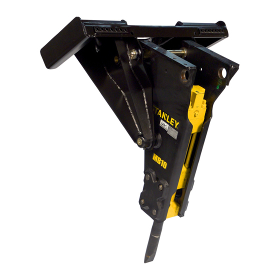
- Page 1 MB10 MOUNTED HYDRAULIC BREAKER USER MANUAL Safety, Operation and Maintenance © 2017 STANLEY Black & Decker, Inc. New Britain, CT 06053 U.S.A. 76818 10/2018 Ver. 8...
-
Page 3: Table Of Contents
REPAIRS AND / OR SERVICE TO THIS TOOL MUST ONLY BE DONE BY AN AUTHORIZED AND CERTIFIED DEALER. For the nearest certified dealer, call STANLEY Infrastructure at (503) 659-5660 and ask for a Customer Service Representative. MB10 User Manual ◄ 3... -
Page 4: Safety Symbols
Always observe safety symbols. They are included for your safety and for the protection of the tool. LOCAL SAFETY REGULATIONS Enter any local safety regulations here. Keep these instructions in an area accessible to the operator and maintenance personnel. 4 ► MB10 User Manual... -
Page 5: Safety Precautions
The decals must be replaced if illegible. Replacement decals can be obtained from your authorized Stanley Wear Eye Distributor. Protection • When operating the breaker you must use ear protection, eye protection, and breathing protection. MB10 User Manual ◄ 5... - Page 6 Know the limits of your equipment. the space provided in this manual. • Establish a training program for all operators to en- The MB10 Mounted Hydraulic Breaker will provide safe sure safe operation. and dependable service if operated in accordance with •...
- Page 7 • Do not modify the breaker in any manner. • Use only tool bits supplied by STANLEY. Use of tool bits supplied by another manufacturer may damage the breaker and will void the warranty. •...
-
Page 8: Tool Stickers & Tags
Composite Warning Sticker 66764 Made in USA Sticker 74705 STANLEY Logo Sticker 70972 Grease Sticker 70754 Nitrogen Sticker 200-PSI 70971 Information Sticker for MB10S02 / S05 70961 Information Sticker for MB10E00 / E05 / E09 8 ► MB10 User Manual... -
Page 9: Operation
2. Be sure the fluid in the hydraulic system is clean. 3. Check the hydraulic filter. Replace the filter if dirty or deteriorated. 4. Have your STANLEY dealer test the circuit to which the breaker will be connected to make sure that the Grease Fitting circuit is supplying the specified flow and pressure rating for the breaker. - Page 10 3. Grease the top area of the tool bit as shown in the illustration on page 9. 4. Install the tool bit making sure the notch is aligned with the lower body retainer pin holes. 5. Install the tool retainer. LOW TEMPERATURE WARM-UP 10 ► MB10 User Manual...
- Page 11 If the tool is positioned in the center of the work, or too far from the edge, the energy will be absorbed into the material without cracking it. Do not run the breaker longer than MB10 User Manual ◄ 11...
- Page 12 Many materials do not respond well to continued ham- mering in one place. The breaker tool should be repo- sitioned on the work each time the tool penetrates but does not crack the material. Scoring with the breaker 12 ► MB10 User Manual...
- Page 13 The best approach to this problem is to use a chisel point tool which permits cut- ting the rebar with the breaker. Another method is to pe- riodically cut the rebar with an oxy-acetylene torch MB10 User Manual ◄ 13...
- Page 14 Do not use underwater without supplying air to breaker. No part of the breaker may be submerged in water. Underwater usage of the breaker will cause internal damage to the breaker. Consult STANLEY for modifications and specific warranty coverage if you have an underwater requirement.
-
Page 15: Troubleshooting
This section describes how to find and resolve problems users may experience. If a situation occurs that is not covered, call your STANLEY Customer Service representative for assistance. Inspecting the tool or installing parts with the hydraulic hoses connected can result in severe personal injury or equipment damage. -
Page 16: Maintenance
Do not just replace the tool bit or the lower bushing individually as this will result in premature wear of the replaced component. It is recommended to replace ALL worn components. 16 ► MB10 User Manual... -
Page 17: Charging The Accumulator
505232 charge hose assy and the 76485 ac- tract the plunger. Then, loosen and remove the tes- cumulator tester which are used with other STANLEY ter from the charge valve. If the pressure is not cor- model breakers. When charging the accumulators, rect, proceed to Step number 6. -
Page 18: Wear Tolerances
To increase the life of the tool stop, remove the tool stop after normal wear has developed and rotate the tool stop 90° and lock into the second slot. Note: the tool stop is not sym- metrical and can not be flipped from end to end. 18 ► MB10 User Manual... -
Page 19: Proper Care Of Tool Bits
Special care damage from occurring again. should be taken to keep the tool shank lubricated every All STANLEY tool bits are machined and hardened for two (2) to three (3) hours. maximum performance. Care must be taken to maintain... - Page 20 As the next illustration shows, fatigue failures take many forms, but they all exhibit similar features. Generally, the broken surface is brittle and has a “lip” like that in the bending failure, even though, in some cases, the lip has been broken. 20 ► MB10 User Manual...
- Page 21 Stress failures start small, and spread into the center of the steel. In a stress failure, the coarser the grain, the greater the stress was, and the more rapid was the failure. MB10 User Manual ◄ 21...
- Page 22 PROPER CARE OF TOOL BITS STANLEY Breakers are available with several different types of tool bits. The most common are the conical, chisel and the blunt. Each of these working steels has its own purpose as described below: To obtain the maximum production from the breaker, it is important to select the proper working steel.
-
Page 23: Flow Test Procedures
Record the back-pressure psi. 5. Close the restrictor valve on the flow meter until the attachment relief starts to crack or open. The relief valve opens when the flow rate (GPM), indicated on MB10 User Manual ◄ 23... - Page 24 The normal operating temperature range of this circuit will be the typical ambient temperature range for the geographical area plus the heat rise calculated above. Ensure that the operating temperature range is lower than 180° for optimum operation of the attachment. 24 ► MB10 User Manual...
-
Page 25: Definition Of Terms
V60/V65/V100 Valves: A priority flow control valve manufactured by STANLEY. Allows for optimum operation of any attachment by providing the proper amount of flow for opera- tion of the tool the “priority” aspect allows the attachment to function properly if another control function is activated. -
Page 26: Specifications
Weight Skid Steer (with Tool) Weight Excavator (with Tool) Note: Weights, dimensions and operating specifications listed on this sheet are subject to change without notice. Where specifications are critical to your application, please consult the dealer. 26 ► MB10 User Manual... -
Page 27: Accessories
Accumulator Charge Kit (Includes p/n 505232, 76485 Tester and 372047 Charge Kit Box) ......76492 Accumulator Tester ............................76485 SERVICE TOOLS MB05 / MB10 Service Tool Kit ..........................72742 Service Kit Includes the following: 72574 Valve Sleeve Puller Kit, 29565 Piston Sleeve Removal Tool, 72587 Valve Sleeve Cap Puller and Capscrew 32412. -
Page 28: Mb10 Power Cell Illustration
MB10 POWER CELL ILLUSTRATION 28 ► MB10 User Manual... -
Page 29: Mb10 Power Cell Parts List
MB10 POWER CELL PARTS LIST ITEM # PART # DESCRIPTION 09728 PIN RETAINER SPRING 09764 PIN RETAINER 16549 DOWEL PIN 1/2 X 1-1/4 LG. 19095 O-RING* 20694 ROD WIPER* 21645 O-RING* 22980 RETAINER SPRING 22993 TIE ROD WASHER 62233 ROD SEAL* 65039 ROLL PIN .750 DIA X 1.500... -
Page 30: Mb10E00 Housing Parts
NYLOCK NUT 7/8-14UNF 70972 DECAL, GREASE 70754 DECAL, NITROGEN 200 PSI 72499 NYLOCK NUT 3/4-16UNF 70891 POWER CELL 70961 DECAL, MB10E INFO EXCA- VATOR 70929 DECAL, "MB10" 70971 DECAL, MB10S INFO 70933 CAPSCREW 74705 DECAL,STANLEY LOGO 30 ► MB10 User Manual... -
Page 31: Mb10E05 / Mb10E09
MB10E05 / MB10E09 MB10E05 WITH EXCHANGE TOP BRACKET MB10E09 WITH 1/4 YD WAINROY BRACKET ITEM PART # DESCRIPTION 70962 EXCHANGE TOP BRACKET 70965 1/4 YD WAINROY BRACKET MB10 User Manual ◄ 31... -
Page 32: Mb10S02 Cradle Brkt Illustration & Parts List
COMES WITH ALL PARTS SHOWN IN PARTS LIST EXCEPT ITEMS 2, 3, 5, 6 & 70969 BOOM PIN - MB10 70970 BUSHING 74707 DECAL, STANLEY LOGO 371054 WASHER 1-1/2 371500 NYLOCK NUT 1/2-13UNC 372089 LYNCH PIN 32 ► MB10 User Manual... -
Page 33: Mb10S05 Skid Steer Exchange Brkt
COUPLER F.F. MALE 43533 WASHER 3/4" I.D. 65811 COUPLER F.F. FEMALE 70933 CAPSCREW 70951 ADAPTOR 90 70952 HOSE, SKID STEER 70962 EXCHANGE TOP 72499 NYLOCK NUT 3/4-16UNF 73369 EXCHANGE SS BRACKET 73387 EXCHANGE PIN 74707 DECAL, STANLEY MB10 User Manual ◄ 33... - Page 36 STANLEY Infrastructure 6430 SE Lake Road Portland, Oregon 97222 USA (503) 659-5660 / Fax (503) 652-1780 www.stanleyinfrastructure.com...
Need help?
Do you have a question about the MB10 and is the answer not in the manual?
Questions and answers