Sign In
Upload
Download
Table of Contents
Contents
Add to my manuals
Delete from my manuals
Share
URL of this page:
HTML Link:
Bookmark this page
Add
Manual will be automatically added to "My Manuals"
Print this page
×
Bookmark added
×
Added to my manuals
Manuals
Brands
Di-LOG Manuals
Measuring Instruments
DL6799
Instruction manual
Di-LOG DL6799 Instruction Manual
200a truerms current, voltage & continuity tester
Hide thumbs
1
2
Table Of Contents
3
4
5
6
7
8
9
10
11
12
13
14
15
16
17
18
19
20
21
22
23
24
25
26
27
28
29
30
31
32
33
34
35
36
37
38
page
of
38
Go
/
38
Contents
Table of Contents
Bookmarks
Table of Contents
Table of Contents
Overview
DL6799 Box Contents
Safety Notices
Electrical Symbols
Appearance Overview
Function Keys
Technical Index
General Specification
Environmental Limits
Electrical Specification
Measurement Operation
Measuring of AC Current (ACI)
Measuring of DC Current (DCI)
Measuring of AC Voltage (ACV)
Measuring of DC Voltage (DCV)
Measurement of Resistance (OHM)
IX. Maintenance, Repair & Calibration
Continuity Testing (CON)
Diode Measurement (DIO)
Measuring of Capacitance (CAP)
Non-Contact Voltage Detection (NCV)
Single Pole Detection (SPD)
General Maintenance
Maintenance, Repair & Calibration
The Installation or Replacement of Batteries
Advertisement
Quick Links
Download this manual
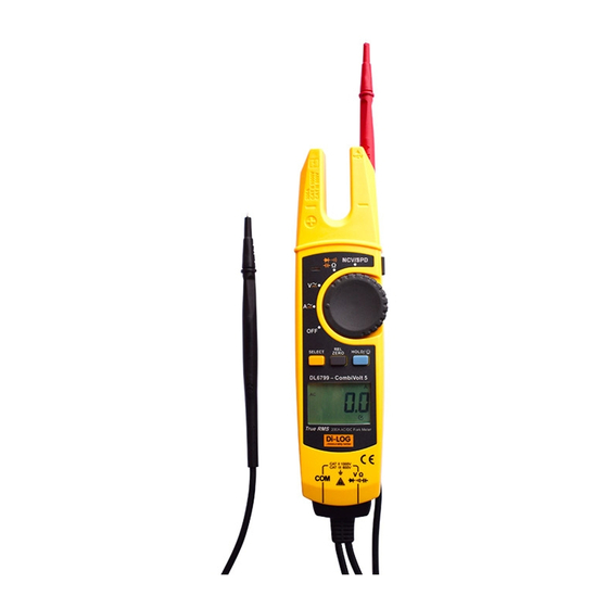
DL6799 - CombiVolt™5
200A TrueRMS Current,
Voltage & Continuity Tester
Table of
Contents
Previous
Page
Next
Page
1
2
3
4
5
Advertisement
Table of Contents
Need help?
Do you have a question about the DL6799 and is the answer not in the manual?
Ask a question
Questions and answers
Related Manuals for Di-LOG DL6799
Measuring Instruments Di-LOG DL6790 Combi Volt 2 Instruction Manual
Voltage continuity tester (10 pages)
Measuring Instruments Di-LOG DL6780 Combi Volt 1 Instruction Manual
Voltage continuity tester (10 pages)
Measuring Instruments Di-LOG DL6505 Operating Manual
200a ac mini clamp-on meter (13 pages)
Measuring Instruments Di-Log DL6702 Operating Instructions
Clamp-on dca/aca multimeter adaptor (2 pages)
Measuring Instruments Di-LOG DL6507 Operating Manual
Ac leakage current clamp meter (17 pages)
Measuring Instruments Di-LOG DL6506 Operating Manual
Mini ac/dc clamp-on meter (13 pages)
Measuring Instruments Di-LOG DL6519 Quick Start Manual
Trms ac leakage current clamp meter (16 pages)
Measuring Instruments Di-LOG DL7206 Instruction Manual
Microwave leakage meter (5 pages)
Measuring Instruments Di-LOG DL7040 Instruction Manual
Digital light meter (12 pages)
Measuring Instruments Di-LOG DL7030 User Manual
Digital luxmeter (6 pages)
Measuring Instruments Di-LOG DL7031 Instruction Manual
Sound level meter (15 pages)
Measuring Instruments Di-LOG DL6413 Operating Instructions Manual
Ac trms clamp meter (11 pages)
Measuring Instruments Di-LOG DL6414 Operating Instructions Manual
Ac/dc trms clamp meter (11 pages)
Measuring Instruments Di-LOG PL107N Instruction Manual
Voltage detector (12 pages)
Measuring Instruments Di-LOG CombiVolt DL6780 Instruction Manual
Voltage & continuity indicator (16 pages)
Measuring Instruments Di-LOG SL104 Instruction Manual
Solar irradiance survey meter (9 pages)
This manual is also suitable for:
Combivolt 5
Table of Contents
Print
Rename the bookmark
Delete bookmark?
Delete from my manuals?
Login
Sign In
OR
Sign in with Facebook
Sign in with Google
Upload manual
Upload from disk
Upload from URL


Need help?
Do you have a question about the DL6799 and is the answer not in the manual?
Questions and answers