
Related Manuals for Di-LOG DL6414


Summary of Contents for Di-LOG DL6414
- Page 1 Operating Instructions for AC/DC TRMS CLAMP METER 61010-1 CAT IV 600V Please read this manual before switching the meter on. Important safety information included.
-
Page 2: Table Of Contents
Di-LOG Di-LOG ...measurably better ...measurably better DL6414 Operating Manual DL6414 Operating Manual Contents Page I. Certificate of conformity As the manufacturer of the instrument listed below, we I. Certificate of Conformity declare under our sole responsibility that the product: II. Safety III. -
Page 3: Safety
Di-LOG Di-LOG ...measurably better ...measurably better DL6414 Operating Manual DL6414 Operating Manual II. Safety II. Safety (Continued) International Safety Symbol • If the equipment is used in a manner not specified by the This symbol, adjacent to another symbol or terminal,... -
Page 4: Instrument & Manual Symbols
EMC regulations (SI 2016 No. 1091), the Low Voltage Regulation (described in the standard EN 61010-1) The DL6414 meets the standard (2012/19/EU) WEEE Directive in the UK & EU. This marking indicates that this product should not be disposed with other household wastes throughout the EC. -
Page 5: Meter Description
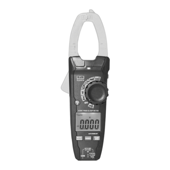
Di-LOG Di-LOG ...measurably better ...measurably better DL6414 Operating Manual DL6414 Operating Manual V. Meter Description VI. Symbols Used on LCD Display Low Impedance Input Mode Current Clamp DC (Direct Current) Non-Contact AC Voltage Detector Light Clamp Trigger Minus Sign Relative / Backlight Button... -
Page 6: Detailed Specifications: Range & Accuracy
Di-LOG Di-LOG ...measurably better ...measurably better DL6414 Operating Manual DL6414 Operating Manual VII. Detailed Specifications: Range & Accuracy 1. General Specifications Clamp Size Opening 1.4” (35mm) Approx. Diode Test Test current of 0.3mA typical; Open circuit voltage 3.2V DC typical Continuity Check Threshold <= 50 Ω;... -
Page 7: Operation
DCV position. 2. Operation • Connect the test leads in parallel to the circuit Rotate the functional dial on the side of the DL6414 under test. from the off position clockwise to the function required. • The measured voltage value will be indicated on Device will automatically power off after approx: the main LCD the display. -
Page 8: Diode Measurements
• Rotate the function dial to the Ω position, the DL6414 is default set to resistance • Insert the 4mm to K-Type adaptor into the negative measurement. COM and the V inputs on the base of the clamp •... -
Page 9: Mode/Inrush Button
• Press the RANGE button. The “Auto Range” display indicator will turn off and the DL6414 will Zeroing Out Offsets: If your meter has a small offset or if enter “Manual Range” mode. there is background noise, specifically static on DC, you Press the RANGE button to step through the available •... -
Page 10: Battery Replacement
20. Warranty & Calibration • To hold the measured reading on the LCD display, Di-LOG instruments are subject to stringent quality press the data hold button. The data hold button is controls. If in the course of normal daily use a fault located on the right side edge of the meter. - Page 11 AC/DC TRMS CLAMP METER Instruction Manual Register your product with us to keep in contact with the latest updates and service reminders. Stay connected with us and be the first to know about our latest news and updates by following us on our social media channels.
Need help?
Do you have a question about the DL6414 and is the answer not in the manual?
Questions and answers