Table of Contents
Advertisement
Quick Links
Advertisement
Table of Contents

Related Manuals for Di-LOG PL107N


Summary of Contents for Di-LOG PL107N
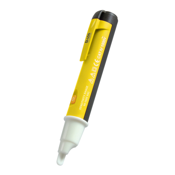
- Page 1 Instruction Manual Voltage Detector - PL107N...
- Page 2 UUT is required. A second connection, e.g.to neutral or ground is not necessary. The voltage tester PL107N does not require maintenance. It is equipped with protective insulation. Power is supplied by means of two 1.5V AAA batteries 1.5V IEC LR03.
- Page 4 Our Service Department will promptly repair any faults that occur outside the guarantee period. Please contact: Di-Log Test Equipment Unit 28, Wheel Forge Way, Trafford Park, Manchester M17 IEH Freephone: 0800 018 9112 Freefax: 0800 018 6711 Sales@dilog.co.uk...
-
Page 5: Safety Measures
Features: • Contact-free voltage test 90V...1000V AC • Display via LED (flashing) acoustic sound signal • Contact-free testing of AC voltages on insulated cables and conductors • Locating line interruptions in insulated cables and conductors • Phase tester of sockets •... - Page 6 Warning! Prior to usage, inspect voltage tester for external damage. Prior to any operation, ensure that voltage tester is in perfect condition. Warning! Prior to opening, the instrument has been switched off and disconnected from any current circuit. Warning! The instrument must only be used under the conditions and for the purposes for which it has been constructed.
-
Page 7: Technical Data
Technical data Voltage range: 90...1000V AC Frequency range: 50Hz...500Hz Display: Clear, omnidirectional flashing beacon IP-Protection: IP40 Overvoltage category: CAT III, 600V Pollution degree: Altitude: up to 3000m Temperature range: --10˚C up to 50˚C Humidity: <80% Power supply: 2 x 1,5V batt. AAA Dimension: 150 x 25 x 20mm Weight:... -
Page 8: Battery Replacement
Battery replacement Batteries: 2 x 1.5V AAA. Slide the two parts of the case apart by holding the unit firmly and pressing the pocket clip forward Warning! If the instrument is likely to remain unused for a long period of time the batteries must be removed. -
Page 9: Display And Control Elements
Display and control elements: 1. Test probe 2. LED for voltage indication 3. Battery case cover 4. Clip 5. Switch Danger! In order to avoid the danger of electrical shock, it is important that proper saftey measures are respected when working with voltages exceeding 120V (60V) DC or 50V (25V) r.m.s. -
Page 10: Operation
Warning! The signal during the voltage test does not provide any indication of the type and level of voltage present. In case of doubt, measure the voltage by using a test instrument with display indication. The voltage tester is delivered with installed batteries. -
Page 11: Application Examples
Application examples: Maintenance As long as the instructions in the operating manual are adhered to, no special maintenance is required. Cleaning Disconnect the instrument from all circuits. Using a damp cloth wipe the instrument surface by applying light pressure. Allow a recovery time of 6 hours after cleaning before operating the instrument.
Need help?
Do you have a question about the PL107N and is the answer not in the manual?
Questions and answers