
Related Manuals for Endress+Hauser mycom COM 121


Summary of Contents for Endress+Hauser mycom COM 121
- Page 1 mycom BA 106C/07/en/09.97 Software version 6.02 or later No. 50063021 COM 121 / 151 / Temperature Transmitter / Controller Operating Instructions µ...
- Page 2 Please familiarise yourself with the instrument before you take any other steps: General information Safety Description You wish to install and start up the instrument. The required steps are described in these chapters: Installation Start-up You wish to operate or reconfigure the instrument. The operating concept is explained in these chapters: Operation Calibration...
-
Page 3: Table Of Contents
COM 121 / 151 Table of contents Table of contents General information ........... 2 Symbols used . -
Page 4: General Information
Note This symbol indicates important items of information. Conformity statement The Mycom COM 121 / 151 has been developed and manufactured in accordance with currently valid European standards and directives. Note: The corresponding certificate of conformity may be requested from Endress+Hauser. -
Page 5: Safety
Mycom COM 121 / 151 Mycom family of instruments: equipped with all the options. Mycom Serial Interfaces The Mycom COM 121 / 151 is a BA 090C/07/en microprocessor-based measuring and control instrument used to The separate operating instructions determine the dissolved O value. -
Page 6: Description
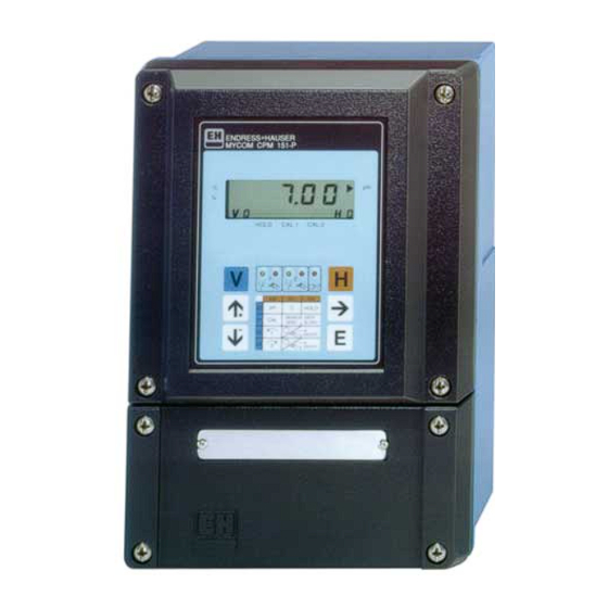
• the O measuring instrument Mycom COM • Drinking water 151 in the field housing • Water monitoring • Fish farming • the Mycom COM 121 instrument in the housing for panel mounting Weather protection cover Filler plug Upright post, square tube 1.4301... -
Page 7: Order Code
COM 121 / 151 Description BE1OM151.CHP Order code Mycom COM 121 / 151 Types 121 dissolved O measuring transmitter for panel mounting, 96 x 96 mm, ingress protection IP 54 (front) 151 field transmitter, 247 x 167 x 111 mm (H x W x D), ingress protection IP 65... -
Page 8: Technical Data
Description mycom COM 121 / 151 Technical data Electrical data measurement with oxygen sensors COS 3 / COS 3S ........0 … 20 mg / l ; 0 … 200 % SAT Display range O Measured value resolution . - Page 9 COM 121 / 151 Description BE1OM151.CHP Electrical data (continued) Electrical data and connections AC power supply ....24, 48, 100, 110, 127, 200, 230, 240 V, –15 … +10 % Frequency .
-
Page 10: Installation
Installation mycom COM 121 / 151 Installation Storage and transport The packaging material used to store or is provided by the original packaging transport the instrument must provide shock materials. Conformance with the ambient and moisture protection. Optimal protection conditions (see technical data) must be assured. - Page 11 COM 121 / 151 Installation BE1OM151.CHP Dimensions of COM 151 For screw ∅ 6 mm Fig. 4.2 : Dimensions of (left) Mycom COM 151 ➀ Brackets for wall installation Fig. 4.3: Rear of field housing (right) with mounting brackets installed ➀...
-
Page 12: Mounting Accessories
Installation mycom COM 121 / 151 Post installation of COM 151 The Mycom COM 151 (field housing) can be These mounting parts are to be installed on installed on vertical or horizontal tubing with a the rear of the instrument according to fig. 4.6. -
Page 13: Connection
COM 121 / 151 Installation BE1OM151.CHP Junction box VS (Order No. 50001054) Junction box VS, equipped with a plug-in socket, is required to extend the length of the standard connecting cable supplied with the COS 3 / COS 3S oxygen sensor (max. length 15 m). - Page 14 Installation mycom COM 121 / 151 Connection of COM 151 The mains and the signal lines are connected to the terminal strip in the separate connection compartment (see fig. 4.10). A plug-in connector is provided for connecting the O sensor.
-
Page 15: Connection Diagram
COM 121 / 151 Installation BE2OM151.CHP Connection diagram Temperature Fault signaling signal contact Switching Switching Mains output (closed circuit contact 2 contact 1 voltage connection Type 151: L+ L- 24 V DC Type 121: L+ L- 24 V DC... -
Page 16: Start-Up
Start-up mycom COM 121 / 151 Start-up Measures before first Measures after first power-up power-up • Calibrate the instrument as described in Familiarise yourself with the operation of the measuring transmitter before switching it on chapter 7. for the first time. -
Page 17: Operation
COM 121 / 151 Operation BE3OM151.CHP Operation General notes on operation Measured value Indicator / display status arrows Relay switching Display of state LEDs selected matrix field position Alarm LED Function keys: Function keys: Vertical matrix Horizontal matrix field selection... -
Page 18: Key Functions
Operation mycom COM 121 / 151 Key functions Matrix position Value range V / H for display or entry V key: Display for locked matrix fields: Selection of row: matrix fields V0 to V9 Each key stroke increases the V (row) display value by one. -
Page 19: Hold Function
COM 121 / 151 Operation BE3OM151.CHP Note: 1. Code 0000 is always displayed in matrix field V8 / H9 when the instrument is started up for the first time or after power failures. 2. Only matrix field V8 / H9 can be selected directly with the ,, E “... -
Page 20: Operating Matrix
Operating matrix mycom COM 121 / 151 Measurement Temperature 1111 HOLD 2222 Toggle 0.0 to 22.0 mg/l display 0 ... 20 mA / OFF / ON 0.0 to 220.0 % SAT –20 to +60 °C 4 ... 20 mA 0 = OFF... - Page 21 COM 121 / 151 Operating matrix BDXOM151.CHP 2222 Rate of rise 2222 at 0 / 4 mA 2222 at 20 mA 2222 Temperature 2222 Temperature 2222 Calibration mA / s 0.0 to 10.0 mg / l 2.0 to 20.0 mg / l...
-
Page 22: Calibration
Calibration mycom COM 121 / 151 Calibration During calibration, the measuring transmitter Measures for first calibration and is adapted to the sensor characteristics. recalibration Since the COS 3 / COS 3S sensor does not • Pull off the sensor protection cap. - Page 23 COM 121 Short Operating Instructions / Configuration mycom COM 151 Supplement to operating instructions BA 106C/07/en Instrument front panel Status arrow active Value display Status arrow passive (digit that can be (invisible) edited flashes) Horizontal µ matrix field Vertical...
- Page 24 Operating matrix mycom COM 121 / 151 Measurement Temperature 1111 HOLD 2222 Toggle 0.0 to 22.0 mg / l display 0 ... 20 mA / OFF / ON 0.0 to 220.0 % SAT –20 to +60 °C 4 ... 20 mA...
- Page 25 COM 121 / 151 Operating matrix KE-OM151.CHP 2222 Rate of rise 2222 at 0 / 4 mA 2222 at 20 mA 2222 Temperature 2222 Temperature 2222 Calibration mA / s 0.0 to 10.0 mg / l 2.0 to 20.0 mg / l...
- Page 26 Calibration and Diagnosis mycom COM 121 / 151 Calibration Calibration sequence Step Matrix Command Meaning Note: • After start-up or interruptions in operation, allow the sensor V8 / H9 1111 Unlock to polarise for 30 ... 60 minutes • Clean the sensor with water and dry Calibration •...
-
Page 27: Calibration Sequence
COM 121 / 151 Calibration BE3OM151.CHP Calibration sequence Matrix field V1 / H0 (code 1111) Matrix Instrument Function field or Display value Note display command Select calibration V1 / H0 Calibration function timer starting value Switch on HOLD Status arrow Only with →... -
Page 28: Description Of Operating Functions
Description of operating functions mycom COM 121 / 151 Description of operating functions Matrix Description of functions Parameter pos. settings V / H Fact. User 0 / 0 Measurement Displays the temperature-compensated O value in concentration units (0.0 to 22.0 mg/l) or optionally as a saturation index percentage (0.0 to 220 % SAT). - Page 29 COM 121 / 151 Description of operating functions BE4OM151.CHP Matrix Description of functions Parameter pos. settings V / H Fact. User 1 / 0 Calibration See description in chapter 7, Calibration. 1 / 1 Toggle mg / l <—-> % SAT Toggles the measured value display between mg / l O SAT % (saturation index percentage).
- Page 30 Description of operating functions mycom COM 121 / 151 Matrix Description of functions Parameter pos. settings V / H Fact. User Values in parentheses apply to setpoint 2. 2 / 5 Toggle MIN / MAX (3 / 5) Determines the function of contact 1:...
- Page 31 COM 121 / 151 Description of operating functions BE4OM151.CHP Matrix Description of functions Parameter pos. settings V / H Fact. User 7 / 2 Toggle steady / fleeting contact Defines the alarm relay as a steady or fleeting contact.
- Page 32 Description of operating functions mycom COM 121 / 151 Matrix Description of functions Parameter pos. settings V / H Fact. User 9 / 1 Service Displays the number of automatic resets. 0 … 255 – The display value can be reset to 0 with the ↑...
- Page 33 COM 121 / 151 Description of operating functions BE4OM151.CHP Matrix Description of functions Parameter pos. settings V / H Fact. User 9 / 8 Simulation ON / OFF 0 = simulation OFF 1 = simulation ON Enter 0 to disable the simulation function.
-
Page 34: Limit Contacter And Time Interval Control
Limit contacter and time interval control mycom COM 121 / 151 Limit contacter and time interval control Limit contacter function MAX function MIN function 100 % 50 % Hysteresis Hysteresis mg/l % Limit 1 (2) Limit 2 (1) Fig. 9.1:... -
Page 35: Switching Contact Configuration
COM 121 / 151 Limit contacter and time interval control BE5OM151.CHP Switching contact configuration The following table shows all the operating Different switching contact positions states for the limit contacter function of the (0 = OFF, 1 = ON) will result depending on unit. -
Page 36: Alarm Function / Fault Signalling Contact
Limit contacter and time interval control mycom COM 121 / 151 Alarm function / fault signalling contact Fault signalling contact Sequence of Matrix position parameter settings V / H Operating Contact Setpoint controller 1 2 / 0 condition 41/42 controller 2... -
Page 37: Time Interval Control (Timer Function)
COM 121 / 151 Limit contacter and time interval control BE5OM151.CHP Time interval control Parameter setting Matrix position (timer function) sequence V / H V / H (Contr. 1) (Contr. 2) The interval control function can be used, for... - Page 38 Limit contacter and time interval control mycom COM 121 / 151 Settings for nitrification or denitrification time interval control (example) Nitrification at: 3.0 mg / l O Hysteresis: 0.3 mg / l Denitrification at: 0.3 mg / l O Hysteresis: 0.1 mg / l...
-
Page 39: Diagnosis
COM 121 / 151 Diagnosis BE6OM151.CHP 10. Diagnosis 10.1 Error classes and 10.2 Error display and error numbers handling Errors are grouped into three classes: Each of the errors described below is entered in an error list which is sorted by the error... -
Page 40: Error List
Diagnosis mycom COM 121 / 151 10.3 Error list Field Measures for Meaning V / H maintenance / troubleshooting System errors Data exchange error in processor Return instrument to your Endress+Hauser sales agency for repair or request service. Return instrument to your... - Page 41 COM 121 / 151 Diagnosis BE6OM151.CHP Field Measures for Meaning V / H maintenance / troubleshooting Disturbances ( continued ) Sensor alarm. 0 / 0 Stop measurement. Regenerate The alarm message ,, S E N S “ 0 / 1 sensor or change diaphragm.
-
Page 42: Service And Maintenance
• Ketones • Household cleansers 11.2 Repairs Repair work must only be carried out directly by the manufacturer or by the Endress+Hauser service organization. See the back cover of these operating instructions for an overview of the Endress+Hauser service network. -
Page 43: Accessories
BE7OM151.CHP 11.4 Accessories • Cable OMK The following accessories may be ordered separately for the Mycom COM 121/151: Special cable to extend the connecting line between oxygen sensor COS 3/COS 3S and • Weather protection cover CYY 101 the oxygen instrument; cable with 7 auxiliary Weather protection cover for installation on cores (0.38 mm... -
Page 44: Index
Diagnostic code ....25 Dimensions of Mycom COM 121/151 ..8 Key functions ....16 Dimensions of Mycom COM 151 . - Page 45 COM 121 / 151 Appendix BE8OM151.CHP Manual OFF / ON ... . . 23 Safety ..... 3 Matrix fields .
- Page 48 Tel. 4 68 82 22, Fax 4 66 68 48 Belarus Belorgsintez Poland Colombia South Korea Minsk ❑ Endress+Hauser Polska Sp. z o.o. Colsein Ltd. Hitrol Co. Ltd. Tel. (01 72) 26 31 66, Fax (01 72) 26 31 11 Warsaw Santafe de Bogota D.C. Bucheon City Tel.
Need help?
Do you have a question about the mycom COM 121 and is the answer not in the manual?
Questions and answers